Y9SMPTXWireless Electromyograph
Cometa Sas di A. Dellacorna & C.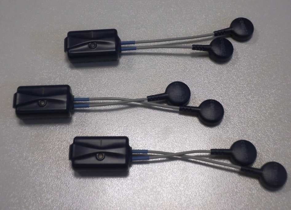
Click to zoom
Application Details
- Equipment Class
- DXX - Part 15 Low Power Communication Device Transmitter
- Date of Grant
- May 13, 2014
- Application Purpose
- Original Equipment
- Date of Application
- May 12, 2014
- Equipment Note
- Wireless Electromyograph
- Frequency Range
- 2402.00000000 - 2480.00000000
- Country
- Italy
Documents & Files
Document Text
Text extracted from the exhibit documents filed with the FCC. Open a document above to read the original.
Users Manual
WAVE PLUS - USER MANUAL C OD. WPMEMG REV 02 02/11/2011 D ATA PRIMA EMISSIONE Pag. 1 di 41 “WAVE PLUS” MULTICHANNEL ELECTROMYOGRAPH USER MANUAL Redaction: SALES – M. DELLACORNA GM – A. DELLACORNA Check: GM – A. DELLACORNA Approval: GM – A. DELLACORNA Data: 24/02/2012 Revision: 01 Code: WPMENG Revision: Revision: Approval Date: Changes Description: 01 24/02/2012 Revision post IMQ review 02 30/12/2013 Added new miniwave electrode The system is classified according to 93/42/CEE regulation This device complies with Part 15 of the FCC Rules. Operation is subject to the following two conditions: (1) this device may not cause harmful interference, and (2) this device must accept any interference received, including such that may cause undesired operations. Any change or modification not expressly approved by Cometa Srl for compliance could void the user’s authority to operate the equipment. WAVE PLUS - USER MANUAL C OD. WPMEMG REV 02 02/11/2011 D ATA PRIMA EMISSIONE Pag. 2 di 41 Table of Contents 1. INTRODUCTION ...................................................................................................................................................................... 3 2. DESTINATION AND CLASSIFICATION ............................................................................................................................. 3 2.1 HOW TO USE IT ........................................................................................................................................................................................ 5 3. WAVE PLUS SYSTEM COMPONENTS ............................................................................................................................... 6 3.1 FUNDAMENTAL, OPTIONAL AND ACCESSORY COMPONENTS ............................................................................................................ 7 3.2 STANDARD WIRELESS ELECTRODES ..................................................................................................................................................... 7 3.3 MINIATURIZED WIRELESS ELECTRODES ............................................................................................................................................. 9 3.4 BASE UNIT ............................................................................................................................................................................................. 10 3.5 DOCKING MODULE ............................................................................................................................................................................... 11 4. WAVE PLUS SYSTEM USE .................................................................................................................................................. 12 4.1 ANALOG MODE ..................................................................................................................................................................................... 12 4.1.1 Supported external devices .................................................................................................................................................... 13 4.1.2 Layout of cable connections .................................................................................................................................................. 14 4.2 DIGITAL MODE ...................................................................................................................................................................................... 15 4.2.1 External trigger .......................................................................................................................................................................... 16 4.2.1.1 Trig in ............................................................................................................................................................................................................ 17 4.2.1.2 Trig out ......................................................................................................................................................................................................... 17 4.2.1.3 Strobe IO ...................................................................................................................................................................................................... 17 4.2.1.4 How to use the Trigger port ............................................................................................................................................................... 18 4.2.2 Supported external devices .................................................................................................................................................... 19 4.3 LED SIGNALLING DURING OPERATION ............................................................................................................................................. 20 4.3.1 Base unit LEDs: ........................................................................................................................................................................... 20 4.3.2 Electrode unit LED: ................................................................................................................................................................... 20 4.4 PRE-GELLED ELECTRODES.................................................................................................................................................................. 20 4.5 ELECTRODES BATTERY RECHARGE ................................................................................................................................................... 21 4.5.1 LED indicator of the charging module .............................................................................................................................. 21 4.5.2 LED indicator of the electrodes …
Text truncated - open the document above for the full version.
Block Diagram
MINIWAVE BLOCK DIAGRAMS Electrode block diagram A/D CONVERTER LOW POWER SINGLE CHIP MICROCONTROLLER AND RF TX 2400 MHz RX 2400 MHz DATA INTERFACE DIGITAL FILTERING BUFFER MEMORY DATA INTERFACE VOLTAGE REGULATOR LI – ION BATTERY RF SINTETIZER RX – TX EMBEDDED WHIP ANTENNA MCU SINCRO INSTRUMENTATION AMPLIFIER
ID Label/Location Info
Etichetta MINIWAVE FCC ID and the CE mark are impressed with laser etching on the outside bottom of the device
Operational Description
OPERATIONAL DESCRIPTION To transfer information (data and control) from and to the electrodes, Wave Plus uses a single RF frequency in the ISM band, with GFSK modulation. Data are transferred from electrodes to the main receiver on a 14 mSec. frame basis; during the frame, each electrode has its own time slot to transmit a burst of data (Max Duty cycle: Ton=0.211ms x 14 pulses= 2.954ms. Ton+Toff= 100ms). At the beginning of each frame, the main receiver broadcasts a strobe signal to activate and lock the electrodes to the main cycle. The output power and frequency of the RF modules are programmed in firmware at production time; these parameters are not alterable by the user. The MINIWAVE electrode RF module is based on the single chip 2.4 GHz transceiver (nRF24LE1 from Nordic Semiconductors). The block schematic of this device follows: This device contains all the RX/TX functions, and requires only an external crystal of 16.000 MHz, an external matching network to adapt the balanced ANT1/ANT2 input to the unbalanced 50 ohm antenna. The MINIWAVE electrode is equipped with one nRF24LE1. The device is switched between RX and TX on a single frequency as follow: - RX, to receive the activation command from the main receiver unit. The RX is also used during the operating phase, to lock the electrode to the system cycle. The RF frequency used is always the same for all the electrodes (up to 16 electrodes) - TX, to transmit the EMG data to the main receiver unit. The output power and frequency of the RF modules are programmed in firmware at production time; these parameters are not alterable by the user. The MINIWAVE electrode is equipped with an integral whip antenna, not accessible to the user. The MINIWAVE is the miniaturized version of the WAVEPLUS electrode, already granted with the FCC code Y9SWPTX; all functional characteristics are the same of the standard version.
Test Report
IMQ S.p.A. – Società con Socio Unico Via Quintiliano, 43 I-20138 MILANO tel 0250731 – [email protected] – www.imq.it The results of tests and checks reported in this Test Report refer exclusively to the samples tested and described in the Report itself. This Report shall not be reproduced partially without the written approval of IMQ S.p.A.. TEST REPORT No. ARSO00005 performed in accordance with FCC Rules: Code of Federal Regulations (CFR) no. 47 Part 15 Subpart C Section 15.249 PRODUCT EMG WIRELESS MODULE FOR ELECTROMYOGRAPH MODEL(s) TESTED MINIWAVE FCC ID Y9SMPTX TRADE MARK(s) COMETA APPLICANT COMETA S.r.l. – Via G. Verdi, 24 – 20080 CISLIANO (MI) - ITALY Tested by Roberto Radice Approved by Roberto Colombo [Laboratory Manager] Revision Sheet Release No. Date Revision Description Rev. 0 2014-02-03 First edition Rev. 1 2014-05-08 Added “Maximum data rate” in operating condition at page 6 Digital signed - ARSO00005 Rev.1_TR_FCC Part 15 C Section 15.249_COMETA_Miniwave Mod. TRF FCC - C1 / 1 R & TTE AND A UTOMOTIVE COMPONENTS L ABORATORY IMQ S.p.A. – Società con Socio Unico Via Quintiliano, 43 I-20138 MILANO tel 0250731 – [email protected] – www.imq.it Test Report No. ARSO00005 Date: 2014-05-08 Page 2 of 38 Mod. TRF FCC - C1 /1 R RR R & && & TTE TTETTE TTE AND AND AND AND A AA A UTOMOTIVE COMPONENTS UTOMOTIVE COMPONENTSUTOMOTIVE COMPONENTS UTOMOTIVE COMPONENTS L LL L ABORATORY ABORATORYABORATORY ABORATORY 1. GENERAL DATA SAMPLE Samples received on 2014-01-08 (item sent and sampling by applicant) IMQ reference samples BEM 71345 Samples tested No. 3 Object under analysis recognition Not carried out Except where stated, characteristics of products were taken from client description and were not verified by the laboratory TEST LOCATION Testing dates 2014-01-10 ÷ 2014-01-15 Testing laboratory. IMQ S.p.A. con socio unico - Via Quintiliano, 43 – I-20138 Milano Testing site Via Quintiliano, 43 – I-20138 Milano ENVIRONMENTAL CONDITIONING Parameter Measured Ambient Temperature 25 ÷ 35 °C Relative Humidity 50 ÷ 60 % Atmospheric Pressure 900 ÷ 1000 mbar IMQ S.p.A. – Società con Socio Unico Via Quintiliano, 43 I-20138 MILANO tel 0250731 – [email protected] – www.imq.it Test Report No. ARSO00005 Date: 2014-05-08 Page 3 of 38 Mod. TRF FCC - C1 /1 R RR R & && & TTE TTETTE TTE AND AND AND AND A AA A UTOMOTIVE COMPONENTS UTOMOTIVE COMPONENTSUTOMOTIVE COMPONENTS UTOMOTIVE COMPONENTS L LL L ABORATORY ABORATORYABORATORY ABORATORY 2. REFERENCE DOCUMENT DOCUMENT DATE TITLE 47 CFR Part 15 2008 Radio Frequency Device ANSI C63.4 2009 Methods of Measurement of Radio-Noise Emissions from Low-Voltage Electrical and Electronic Equipment in the Range of 9 kHz to 40 GHz ANSI C63.10 2009 American National Standard for Testing Unlicensed Wireless Devices IMQ S.p.A. – Società con Socio Unico Via Quintiliano, 43 I-20138 MILANO tel 0250731 – [email protected] – www.imq.it Test Report No. ARSO00005 Date: 2014-05-08 Page 4 of 38 Mod. TRF FCC - C1 /1 R RR R & && & TTE TTETTE TTE AND AND AND AND A AA A UTOMOTIVE COMPONENTS UTOMOTIVE COMPONENTSUTOMOTIVE COMPONENTS UTOMOTIVE COMPONENTS L LL L ABORATORY ABORATORYABORATORY ABORATORY 3. UNIT UNDER TEST (EUT) DETAILS GENERAL DATA MODEL (basic) Description MINIWAVE Portable EMG unit. VARIANTS (derived) Description None FCC ID Y9SMPTX Manufacturer COMETA S.r.l. – Via G. Verdi, 24 – 20080 CISLIANO (MI) - ITALY Type of equipment EMG unit for wireless electromyograph Operating frequency: 2402÷2480MHz Maximum RF radiated power: 86,98 dBμV/m Modulation: FSK Channel Spacing: None Antenna: Integrated on PCB RX sensitivity: / Main SW identification / Main HW Board identification MBAT V01 & MEMG V05 Peripherals included (for system application) None Interfaces None Integrated interfaces None AC adapter: None Data cable None Telecom cable None Power supply type None IMQ S.p.A. – Società con Socio Unico Via Quintiliano, 43 I-20138 MILANO tel 0250731 – [email protected] – www.imq.it Test Report No. ARSO00005 Date: 2014-05-08 Page 5 of 38 Mod. TRF FCC - C1 /1 R RR R & && & TTE TTETTE TTE AND AND AND AND A AA A UTOMOTIVE COMPONENTS UTOMOTIVE COMPONENTSUTOMOTIVE COMPONENTS UTOMOTIVE COMPONENTS L LL L ABORATORY ABORATORYABORATORY ABORATORY 4. TEST CONFGURATION OF UNIT UNDER TEST EUT PORTS Port Description Max length Enclosure Plastic enclosure / AC power Port not present / DC power Internal rechargeable LI-ION battery 4,2V / Earth Port not present / Telecommunication Port not present / Signal Port not present / Control Port not present / Antenna Integrated on PCB / CHANNEL CONFIGURATION Channel (No.) Selectable frequency (MHz) 01 2402 2456 2410 2464 2418 2472 2426 2480 2440 N.B. the equipment is a single frequency channel; the frequency is setting via software by the manufacturer; the user cannot change the working frequency. EUT Antenna Port AC Power Port Earth Port Telecommunication Port Signal/Control Port DC Power Port Enclosure Port IMQ S.p.A. – Società con Socio Unico Via Quintiliano, 43 I-20138 MILANO tel 0250731 – [email protected] – www.imq.it Test Report No. ARSO00005 Date: 2014-05-08 Page 6 of 38 Mod. TRF FCC - C1 /1 R RR R & && & TTE TTETTE TTE AND AND AND AND A AA A UTOMOTIVE COMPONENTS UTOMOTIVE COMPONENTSUTOMOTIVE COMPONENTS UTOMOTIVE COMPONENTS L LL L ABORATORY ABORATORYABORATORY ABORATORY STATE OF THE EUT DURING TESTS Ref. Mode Description #1 Operating Continuous transmission (single channel transmission) with maximum data rate. SUPPORT EQUIPMENT Defined as equipment needed for correct operation or loading of the EUT, but not considered as tested: Equipment Manufacturer Model Electromyograph COMETA WAVE PLUS EMG ELECTROMAGNETICALLY RELEVANT COMPONENTS Component No. Manufacturer Model RF module 1 Nordic Semiconductors nRF24LE1 RFI SUPPRESSION DEVICES Component No. Manufacturer Model None EMI PROTECTION DEVICES Component No. Manufacturer Model None EUT TECHNICAL DOCUMENTATION Document Reference Wave Plus – Multichannel Electromyograph WPMEMG Rev.02 IMQ S.p.A. – Società con Socio Unico Via Quintiliano, 43 I-20138 MILANO tel …
Text truncated - open the document above for the full version.
Contact Information
Applicant
Matteo Dellacorna
Technical Contact
Test Firm
Istituto Italiano del Marchio di Qualita' S.p.A.Eng. Fulvio Giorgi
Technical Specifications
| # | Rule Parts | Frequency Range | Power Output |
|---|---|---|---|
| 1 | 15C | 2.40 GHz - 2.48 GHz | - |
Other Applications from Cometa Sas di A. Dellacorna & C.
Y9SWPRX
Nov 21, 2012Wireless Electromyograph
Equipment Class
DXX - Part 15 Low Power Communication Device Transmitter