Y9SWPRXWireless Electromyograph
Cometa Sas di A. Dellacorna & C.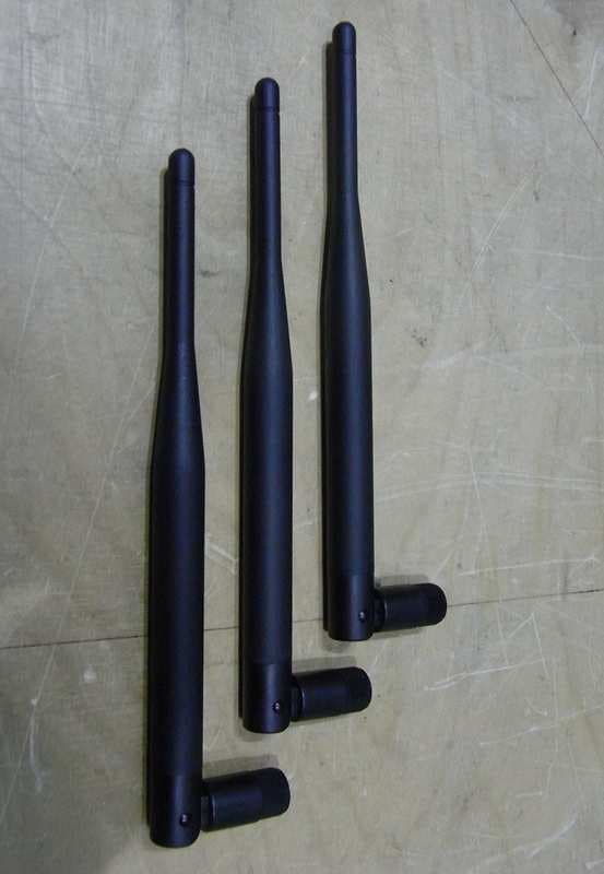
Click to zoom
Application Details
- Equipment Class
- DXX - Part 15 Low Power Communication Device Transmitter
- Date of Grant
- Nov 21, 2012
- Application Purpose
- Original Equipment
- Date of Application
- Nov 21, 2012
- Equipment Note
- Wireless Electromyograph
- Frequency Range
- 2402.00000000 - 2480.00000000
- Country
- Italy
Documents & Files
Document Text
Text extracted from the exhibit documents filed with the FCC. Open a document above to read the original.
Block Diagram
BLOCK DIAGRAMS AND OPERATIONAL DESCRIPTION Electrode block diagram A/D CONVERTER LOW POWER SINGLE CHIP MICROCONTROLLER TX 2400 MHz RF SINGLE – CHIP RX 2400 MHz DATA INTERFACE DIGITAL FILTERING BUFFER MEMORY DATA INTERFACE VOLTAGE REGULATOR LI – ION BATTERY RF SINTETIZER RX – TX EMBEDDED WHIP ANTENNA MCU SINCRO INSTRUMENTATIO N AMPLIFIER DIVERSITY MODE RF INTERFACE RX – TX 2400 MHz RX – TX 2400 MHz MCU DATA MEMORY USB INTERFACE DIVERSITY SWITCH D/A CONVERTER ANALOG OUTPUTS TO PERSONAL COMPUTER Receiver block diagram OPERATIONAL DESCRIPTION To transfer information (data and control) from and to the electrodes, Wave Plus uses a single RF frequency in the ISM band, with GFSK modulation. Data are transferred from electrodes to the main receiver on a 14 mSec. frame basis; during the frame, each electrode has its own time slot to transmit a burst of data. At the beginning of each frame, the main receiver broadcasts a strobe signal to activate and lock the electrodes to the main cycle. The output power and frequency of the RF modules are programmed in firmware at production time; these parameters are not alterable by the user. The receiver and electrode RF module is based on the same single chip 2.4 GHz transceiver (nRF24L01+ from Nordic Semiconductors). The block schematic of this device follows: This device contains all the RX/TX functions, and requires only an external crystal of 16.000 MHz, an external matching network to adapt the balanced ANT1/ANT2 input to the unbalanced 50 ohm antenna, and a MCU to control it. ELECTRODE Each electrode is equipped with one RF module, controlled by a low power MCU. The device is switched between RX and TX on a single frequency as follow: - RX, to receive the activation command from the main receiver unit. The RX is also used during the operating phase, to lock the electrode to the system cycle. The RF frequency used is always the same for all the electrodes (up to 16 electrodes) - TX, to transmit the EMG data to the main receiver unit. MAIN RECEIVER The main receiver is equipped with three RF modules, controlled by a MCU. They work as follow: - Two RF modules are programmed as receiver, on the same frequency, and work as a “diversity receiver”; - One RF module is programmed as transmitter, on the same frequency, and is used to broadcast the strobe signal used to activate and synchronize the electrodes. The output power and frequency of the RF modules are programmed in firmware at production time; these parameters are not alterable by the user. ANTENNAS The electrode is equipped with an integral whip antenna, not accessible to the user. The main receiver is equipped with three SMA connectors and three rubber antennas are supplied. The compliance with the FCC 15.203 is verified as follow: - The SMA connector used in Wave Plus is the professional type, and it does not mate with the commonly used “RP” SMA (reverse polarity) used by the commercial WI-FI antennas available on the market; - A warning is included in the user manual as follow: “The main unit is supplied with three rubber antennas that have been selected and certified by the producer to get the best result in every application; the use of different antennas could cause malfunctions or could lead to exceed the specifications of the FCC and CE certification of the device.”
Operational Description
BLOCK DIAGRAMS AND OPERATIONAL DESCRIPTION Electrode block diagram A/D CONVERTER LOW POWER SINGLE CHIP MICROCONTROLLER TX 2400 MHz RF SINGLE – CHIP RX 2400 MHz DATA INTERFACE DIGITAL FILTERING BUFFER MEMORY DATA INTERFACE VOLTAGE REGULATOR LI – ION BATTERY RF SINTETIZER RX – TX EMBEDDED WHIP ANTENNA MCU SINCRO INSTRUMENTATIO N AMPLIFIER DIVERSITY MODE RF INTERFACE RX – TX 2400 MHz RX – TX 2400 MHz MCU DATA MEMORY USB INTERFACE DIVERSITY SWITCH D/A CONVERTER ANALOG OUTPUTS TO PERSONAL COMPUTER Receiver block diagram OPERATIONAL DESCRIPTION To transfer information (data and control) from and to the electrodes, Wave Plus uses a single RF frequency in the ISM band, with GFSK modulation. Data are transferred from electrodes to the main receiver on a 14 mSec. frame basis; during the frame, each electrode has its own time slot to transmit a burst of data. At the beginning of each frame, the main receiver broadcasts a strobe signal to activate and lock the electrodes to the main cycle. The output power and frequency of the RF modules are programmed in firmware at production time; these parameters are not alterable by the user. The receiver and electrode RF module is based on the same single chip 2.4 GHz transceiver (nRF24L01+ from Nordic Semiconductors). The block schematic of this device follows: This device contains all the RX/TX functions, and requires only an external crystal of 16.000 MHz, an external matching network to adapt the balanced ANT1/ANT2 input to the unbalanced 50 ohm antenna, and a MCU to control it. ELECTRODE Each electrode is equipped with one RF module, controlled by a low power MCU. The device is switched between RX and TX on a single frequency as follow: - RX, to receive the activation command from the main receiver unit. The RX is also used during the operating phase, to lock the electrode to the system cycle. The RF frequency used is always the same for all the electrodes (up to 16 electrodes) - TX, to transmit the EMG data to the main receiver unit. MAIN RECEIVER The main receiver is equipped with three RF modules, controlled by a MCU. They work as follow: - Two RF modules are programmed as receiver, on the same frequency, and work as a “diversity receiver”; - One RF module is programmed as transmitter, on the same frequency, and is used to broadcast the strobe signal used to activate and synchronize the electrodes. The output power and frequency of the RF modules are programmed in firmware at production time; these parameters are not alterable by the user. ANTENNAS The electrode is equipped with an integral whip antenna, not accessible to the user. The main receiver is equipped with three SMA connectors and three rubber antennas are supplied. The compliance with the FCC 15.203 is verified as follow: - The SMA connector used in Wave Plus is the professional type, and it does not mate with the commonly used “RP” SMA (reverse polarity) used by the commercial WI-FI antennas available on the market; - A warning is included in the user manual as follow: “The main unit is supplied with three rubber antennas that have been selected and certified by the producer to get the best result in every application; the use of different antennas could cause malfunctions or could lead to exceed the specifications of the FCC and CE certification of the device.”
Test Report
IMQ S.p.A. con socio unico Via Quintiliano, 43 20138 MILANO - I Test Report No. ARSL00305/a Date: 2012-10-09 Page 2 of 40 Mod . T RF FCC - C1 /0 T TT T ELECOMMUNICATIONS ELECOMMUNICATIONS ELECOMMUNICATIONS ELECOMMUNICATIONS & && & T TT T ELEMATICS FOR ELEMATICS FOR ELEMATICS FOR ELEMATICS FOR T TT T RANSPORTS RANSPORTSRANSPORTS RANSPORTS L LL L ABORATORY ABORATORYABORATORY ABORATORY 1. GENERAL DATA SAMPLE Samples received on 2012-01-17 (item sent and sampling by applicant) IMQ reference samples BEM 62416 Samples tested No. 3 (1 for every frequency tested) Object under analysis recognition Not carried out Except where stated, characteristics of products were taken from client description and were not verified by the laboratory TEST LOCATION Testing dates 2012-01-18 ÷ 2012-05-29 Testing laboratory. IMQ S.p.A. - Via Quintiliano, 43 – I-20138 Milano Testing site Via Quintiliano, 43 – I-20138 Milano ENVIRONMENTAL CONDITIONING Parameter Measured Ambient Temperature 25 ÷ 35 °C Relative Humidity 50 ÷ 60 % Atmospheric Pressure 900 ÷ 1000 mbar IMQ S.p.A. con socio unico Via Quintiliano, 43 20138 MILANO - I Test Report No. ARSL00305/a Date: 2012-10-09 Page 3 of 40 Mod . T RF FCC - C1 /0 T TT T ELECOMMUNICATIONS ELECOMMUNICATIONS ELECOMMUNICATIONS ELECOMMUNICATIONS & && & T TT T ELEMATICS FOR ELEMATICS FOR ELEMATICS FOR ELEMATICS FOR T TT T RANSPORTS RANSPORTSRANSPORTS RANSPORTS L LL L ABORATORY ABORATORYABORATORY ABORATORY 2. REFERENCE DOCUMENT DOCUMENT DATE TITLE 47 CFR Part 15 2008 Radio Frequency Device ANSI C63.4 2009 Methods of Measurement of Radio-Noise Emissions from Low-Voltage Electrical and Electronic Equipment in the Range of 9 kHz to 40 GHz ANSI C63.10 2009 American National Standard for Testing Unlicensed Wireless Devices IMQ S.p.A. con socio unico Via Quintiliano, 43 20138 MILANO - I Test Report No. ARSL00305/a Date: 2012-10-09 Page 4 of 40 Mod . T RF FCC - C1 /0 T TT T ELECOMMUNICATIONS ELECOMMUNICATIONS ELECOMMUNICATIONS ELECOMMUNICATIONS & && & T TT T ELEMATICS FOR ELEMATICS FOR ELEMATICS FOR ELEMATICS FOR T TT T RANSPORTS RANSPORTSRANSPORTS RANSPORTS L LL L ABORATORY ABORATORYABORATORY ABORATORY 3. UNIT UNDER TEST (EUT) DETAILS GENERAL DATA MODEL (basic) Description WAVE FORM EMG Wireless Electromyograph (Base unit) VARIANTS (derived) Description None FCC ID Y9SWPRX Manufacturer COMETA S.r.l. – Via G. Verdi, 24 – 20080 CISLIANO (MI) - ITALY Type of equipment Wireless Electromyograph for medical use Operating frequency: 2402÷2480MHz Maximum RF radiated power: 96,46 dBμV/m Modulation: FSK Channel Spacing: None Antenna: External dedicated 6dBi gain antenna RX sensitivity: / Main SW identification / Main HW Board identification WMAIN V02 Peripherals included (for system application) None Interfaces : USB cable for Personal Computer interface Integrated interfaces : None AC adapter: AC/DC Adapter 100÷240V∼/ 50-60Hz/ 400mA – Output 9Vdc/ 1,5A Data cable None Telecom cable None Power supply type : FWGB type FW 755M/09 AC power input cable : None DC power input cable : None IMQ S.p.A. con socio unico Via Quintiliano, 43 20138 MILANO - I Test Report No. ARSL00305/a Date: 2012-10-09 Page 5 of 40 Mod . T RF FCC - C1 /0 T TT T ELECOMMUNICATIONS ELECOMMUNICATIONS ELECOMMUNICATIONS ELECOMMUNICATIONS & && & T TT T ELEMATICS FOR ELEMATICS FOR ELEMATICS FOR ELEMATICS FOR T TT T RANSPORTS RANSPORTSRANSPORTS RANSPORTS L LL L ABORATORY ABORATORYABORATORY ABORATORY 4. TEST CONFGURATION OF UNIT UNDER TEST EUT PORTS Port Description Max length Enclosure Plastic enclosure AC power Input 100÷240Vac/50÷60Hz (from AC/DC power supply) ----- DC power Port not present ----- Earth Port not present ----- Telecommunication Port not present ----- Signal Control Usb Port (for PC connection) Analog outputs < 3m. < 3m. Antenna Dedicated 6dBi antennas (RX and TX) ----- CHANNEL CONFIGURATION Channel (No.) Selectable frequency (MHz) 2402 2410 2418 2426 2440 2456 2464 2472 01 2480 N.B. the equipment is a single frequency channel; the frequency is setting via software by the manufacturer; the user cannot change the working frequency. EUT Antenna Port AC Power Port Earth Port Telecommunication Port Signal/Control Port DC Power Port Enclosure Port IMQ S.p.A. con socio unico Via Quintiliano, 43 20138 MILANO - I Test Report No. ARSL00305/a Date: 2012-10-09 Page 6 of 40 Mod . T RF FCC - C1 /0 T TT T ELECOMMUNICATIONS ELECOMMUNICATIONS ELECOMMUNICATIONS ELECOMMUNICATIONS & && & T TT T ELEMATICS FOR ELEMATICS FOR ELEMATICS FOR ELEMATICS FOR T TT T RANSPORTS RANSPORTSRANSPORTS RANSPORTS L LL L ABORATORY ABORATORYABORATORY ABORATORY STATE OF THE EUT DURING TESTS Ref. Mode Description #1 Operating Continuous transmission (single channel transmission) SUPPORT EQUIPMENT Defined as equipment needed for correct operation or loading of the EUT, but not considered as tested: Equipment Manufacturer Model None ELECTROMAGNETICALLY RELEVANT COMPONENTS Component No. Manufacturer Model Microprocessor 1 MICROCHIP PIC18F46K22 RFI SUPPRESSION DEVICES Component No. Manufacturer Model Ferrite (on DC input cable – 3 turns) 1 / / - 270 Ω at 100 MHz Ferrite (on internal input cable – 15 turns) 1 EASYMAGNET CO. 33RI 25X12X15 – 120 Ω at 100 MHz CM choke 2 WURTH 744272102 EMI PROTECTION DEVICES Component No. Manufacturer Model / EUT TECHNICAL DOCUMENTATION Document Reference WAVE PLUS EMG MULTICHANNEL ELECTROMYOGRAPH – USER MANUAL COD. WPMENG Rev.0 – 02/11/2011 IMQ S.p.A. con socio unico Via Quintiliano, 43 20138 MILANO - I Test Report No. ARSL00305/a Date: 2012-10-09 Page 7 of 40 Mod . T RF FCC - C1 /0 T TT T ELECOMMUNICATIONS ELECOMMUNICATIONS ELECOMMUNICATIONS ELECOMMUNICATIONS & && & T TT T ELEMATICS FOR ELEMATICS FOR ELEMATICS FOR ELEMATICS FOR T TT T RANSPORTS RANSPORTSRANSPORTS RANSPORTS L LL L ABORATORY ABORATORYABORATORY ABORATORY 5. METHODS OF MEASUREMENT All compliance measurements have been carried out using the procedures described in the standard ANSI C63.4-2009, ANSI C63.10-2009 and Section 15.31 of CFR47 Part 15 – Subpart A (General). Add…
Text truncated - open the document above for the full version.
Contact Information
Applicant
Matteo Dellacorna
Technical Contact
Test Firm
Istituto Italiano del Marchio di Qualita' S.p.A.Eng. Fulvio Giorgi
Technical Specifications
| # | Rule Parts | Frequency Range | Power Output |
|---|---|---|---|
| 1 | 15C | 2.40 GHz - 2.48 GHz | - |
Other Applications from Cometa Sas di A. Dellacorna & C.
Y9SMPTX
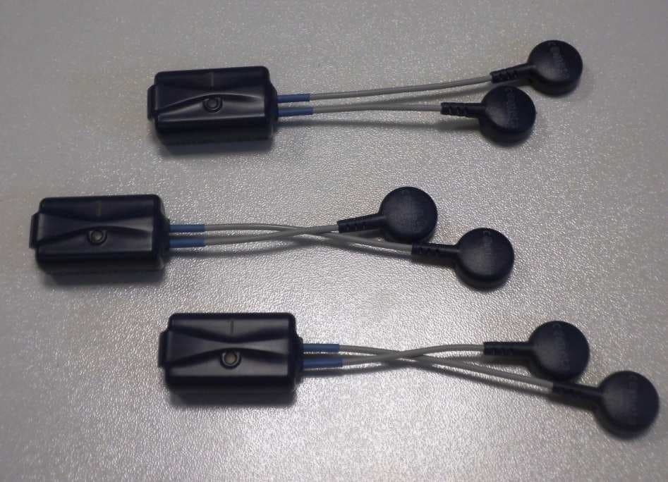
May 13, 2014Wireless Electromyograph
Equipment Class
DXX - Part 15 Low Power Communication Device Transmitter