YAMBP516LFDigital Portable Radio
Hytera Communications Corporation Limited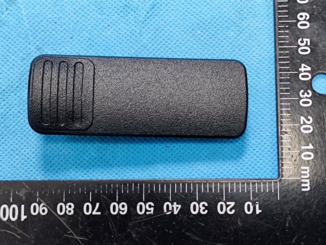
Click to zoom
Application Details
- Equipment Class
- FRF - Part 95 Family Radio Face Held Transmitter
- Date of Grant
- Aug 15, 2022
- Application Purpose
- Original Equipment
- Date of Application
- Aug 15, 2022
- Equipment Note
- Digital Portable Radio
- Frequency Range
- 467.56250000 - 467.71250000
- Country
- China
Documents & Files
Document Text
Text extracted from the exhibit documents filed with the FCC. Open a document above to read the original.
Users Manual
BP51X Digital Portable Radio User Manual Hytera Communications Corporation Limited Preface Welcome to the world of Hytera and thank you for purchasing this product. This manual includes a description of the functions and step-by-step procedures for use. To avoid bodily injury or property loss caused by incorrect operation, please carefully read the Safety Information Booklet before use. This manual is applicable to the following product: BP51X Digital Portable Radio i Contents Documentation Information ........................................................................................................................ 4 1. Packing List .............................................................................................................................................. 6 2. Product Overview ..................................................................................................................................... 7 2.1 Product Layout ..................................................................................................................................... 7 2.2 Programmable Keys ............................................................................................................................. 7 3. Before Use ................................................................................................................................................ 8 3.1 Charging the Battery ............................................................................................................................ 8 3.2 Attaching the Belt Clip .......................................................................................................................... 8 3.3 Attaching the Battery ............................................................................................................................ 9 3.4 Attaching the Audio Accessory ............................................................................................................ 9 3.5 Checking the Battery Power ............................................................................................................... 11 4. Basic Operations .................................................................................................................................... 12 4.1 Turning On or Off the Radio ............................................................................................................... 12 4.2 Adjusting the Volume ......................................................................................................................... 12 4.3 Selecting a Zone ................................................................................................................................. 12 4.4 Selecting a Channel ........................................................................................................................... 12 5. LED Indicator .......................................................................................................................................... 13 6. Call Services ........................................................................................................................................... 14 6.1 Group Call........................................................................................................................................... 14 6.1.1 Initiating a Group Call............................................................................................................... 14 6.1.2 Answering a Group Call ........................................................................................................... 14 6.1.3 Ending a Group Call ................................................................................................................. 14 6.2 Private Call ......................................................................................................................................... 14 6.2.1 Initiating a Private Call ............................................................................................................. 14 6.2.2 Answering a Private Call .......................................................................................................... 14 6.2.3 Ending a Private Call ................................................................................................................ 14 6.3 All Call ................................................................................................................................................. 15 6.3.1 Initiating an All Call ................................................................................................................... 15 6.3.2 Answering an All Call ................................................................................................................ 15 6.3.3 Ending an All Call ..................................................................................................................... 15 6.4 Call on Analog Channel (Without Signaling) ...................................................................................... 15 7. Supplementary Features ....................................................................................................................... 16 7.1 VOX .................................................................................................................................................... 16 7.2 Scan .................................................................................................................................................... 16 7.3 Squelch Level ..................................................................................................................................... 16 7.4 Scrambler ........................................................................................................................................... 16 7.5 Monitor .........................................................…
Text truncated - open the document above for the full version.
Cover Letter(s)
QA-FR-170-B Hytera Communications Corporation Limited Add: Hytera Tower, Hi-Tech Industrial Park North, 9108# Beihuan Road, Nanshan District, Shenzhen, 518057 China Tel: +86-755-26972999 Fax: +86-755-86139020 Email: [email protected] FCC Authorization Date: 2022-07-14 FEDERAL COMMUNICATIONS COMMISSION Authorization and Evaluation Division 7435 Oakland Mills Road Columbia, MD 21046 Subject: Agent Authorization To whom it may concern: We , Hytera Communications Corporation Limited, Hereby authorizes China Certification ICT Co., Ltd (Dongguan) to act on its behalf in all matters relating to application for Equipment authorization, including the signing of all documents relating to these matters. All acts carried out by China Certification ICT Co., Ltd (Dongguan) on our behalf shall have the same effect as our own action. We, the undersigned, hereby certify that we are not subject to a denial of federal benefits, that includes FCC benefits, pursuant to Section 5301 of the Anti-Drug Abuse Act of 1988, 21 U.S.C. 862. This authorization is valid until further written notice from the applicant. Sincerely Yours, Client’s signature Printed Name: Ruifen Huang Title: Certification Engineer
Cover Letter(s)
QA-FR-171-A Hytera Communications Corporation Limited Add: Hytera Tower, Hi-Tech Industrial Park North, 9108# Beihuan Road, Nanshan District, Shenzhen, 518057 China Tel: +86-755-26972999 Fax: +86-755-86139020 Email: [email protected] FCC Confidential Authorization Date: 2022-07-14 FEDERAL COMMUNICATIONS COMMISSIONS Authorization and Evaluation Division 7435 Oakland Mills Road Columbia, MD 21046 Subject: Confidentiality Request regarding application for certification of FCC ID:YAMBP516LF In accordance with Sections 0.457 and 0.459 of the Commission’s Rules, (Hytera Communications Corporation Limited) hereby requests long-term confidential treatment of information accompanying this application as outlined below: Block Diagram Schematics Operation Description The above materials contain proprietary and confidential information not customarily released to the public. The public disclosure of these materials provides unjustified benefits to its competitors in the market. Sincerely, Signature: Printed Name: Ruifen Huang Title: Certification Engineer
Cover Letter(s)
Hytera Communications Corporation Limited Add: Hytera Tower, Hi-Tech Industrial Park North, 9108# Beihuan Road, Nanshan District, Shenzhen, 518057 China Tel: +86-755-26972999 Fax: +86-755-86139020 Email: [email protected] DECLARATION OF SIMILARITY Date: 2022-07-14 FEDERAL COMMUNICATIONS COMMISSION Authorization and Evaluation Division 7435 Oakland Mills Road Columbia, MD 21046 Dear Sir or Madam: We, Hytera Communications Corporation Limited, hereby declare that the product: Digital Portable Radio, FCC ID:YAMBP516LF. model:BP512 LF,BP51X is electrically identical with the model: BP516 LF which was tested by China Certification ICT Co., Ltd (Dongguan) with the same electromagnetic emissions and electromagnetic compatibility characteristics. A description of the differences between those models and that are declared similar are as follows: They are the same product, and just the different model name, the rest are the same. Please contact me should there be need for any additional clarification or information. Best Regards, Signature: Printed Name: Ruifen Huang Title: Certification Engineer
External Photos
EXHIBIT B - EUT EXTERNAL PHOTOGRAPHS Belt Clip Adapter Charger
Internal Photos
EXHIBIT C - EUT INTERNAL PHOTOGRAPHS FRS Antenna Bluetooth Antenna Location Bluetooth Antenna FRS Antenna(Integrated)
RF Exposure Info
SAR TEST REPORT Applicant: Hytera Communications Corporation Limited Address: Hytera Tower, Hi-Tech Industrial Park North, 9108# Beihuan Road, Nanshan District, Shenzhen, 518057 China FCC ID: YAMBP516LF Product Name: Digital Portable Radio Model Number: BP516 LF Multiple Numbers: BP512 LF, BP51X Standard(s): 47 CFR Part 2(2.1093) The above equipment has been tested and found compliant with the requirement of the relative standards by China Certification ICT Co., Ltd (Dongguan) Report Number: CR22060025-20 Date Of Issue: 2022-07-11 Reviewed By: Sun Zhong Title: Manager Test Laboratory: China Certification ICT Co., Ltd (Dongguan) No. 113, Pingkang Road, Dalang Town, Dongguan, Guangdong, China Tel: +86-769-82016888 China Certification ICT Co., Ltd (Dongguan) Report No.: CR22060025-20 Page 2 of 41 SAR TEST RESULTS SUMMARY Operation Frequency Bands Highest Reported 1g SAR (W/kg) Limits (W/kg) Head Face Up (Gap 25mm) Body-Worn (Gap 0mm) PTT(462.5500-467.7125MHz) 0.29 0.31 1.6 Maximum Simultaneous Transmission SAR Items Head Face Up (Gap 25mm) Body-Worn (Gap 0mm) Limits Sum SAR(W/kg) 0.41 0.42 1.6 SPLSR N/A N/A 0.04 EUT Received Date: 2022/06/14 Tested Date: 2022/06/25 Tested Result: Pass China Certification ICT Co., Ltd (Dongguan) Report No.: CR22060025-20 Page 3 of 41 Test Facility The Test site used by China Certification ICT Co., Ltd (Dongguan) to collect test data is located on the No. 113, Pingkang Road, Dalang Town, Dongguan, Guangdong, China. The lab has been recognized as the FCC accredited lab under the KDB 974614 D01 and is listed in the FCC Public Access Link (PAL) database, FCC Registration No. : 442868, the FCC Designation No. : CN1314. The lab has been recognized by Innovation, Science and Economic Development Canada to test to Canadian radio equipment requirements, the CAB identifier: CN0123. Declarations China Certification ICT Co., Ltd (Dongguan) is not responsible for the authenticity of any test data provided by the applicant. Data included from the applicant that may affect test results are marked with a triangle symbol “▲”. Customer model name, addresses, names, trademarks etc. are not considered data. Unless otherwise stated the results shown in this test report refer only to the sample(s) tested. This report cannot be reproduced except in full, without prior written approval of the Company. This report is valid only with a valid digital signature. The digital signature may be available only under the Adobe software above version 7.0. This report may contain data that are not covered by the accreditation scope and shall be marked with an asterisk “★”. China Certification ICT Co., Ltd (Dongguan) Report No.: CR22060025-20 Page 4 of 41 CONTENTS SAR TEST RESULTS SUMMARY .............................................................................................. 2 TEST FACILITY .......................................................................................................................................... 3 DECLARATIONS .......................................................................................................................................... 3 1. GENERAL INFORMATION .................................................................................................... 6 1.1 PRODUCT DESCRIPTION FOR EQUIPMENT UNDER TEST (EUT) ....................................................... 6 1.2 TEST SPECIFICATION, METHODS AND PROCEDURES ........................................................................ 7 1.3 SAR LIMTS ........................................................................................................................................... 8 2. SAR MEASUREMENT SYSTEM ............................................................................................ 9 3. EQUIPMENT LIST AND CALIBRATION .......................................................................... 16 3.1 EQUIPMENTS LIST & CALIBRATION INFORMATION ....................................................................... 16 4. SAR MEASUREMENT SYSTEM VERIFICATION ........................................................... 17 4.1 LIQUID VERIFICATION ...................................................................................................................... 17 4.2 SYSTEM ACCURACY VERIFICATION ................................................................................................. 18 4.3 SAR SYSTEM VALIDATION DATA ............................................................................................. 19 5. EUT TEST STRATEGY AND METHODOLOGY .............................................................. 20 5.1 TEST POSITIONS FOR DEVICE OPERATING NEXT TO A PERSON’S EAR ......................................... 20 5.2 CHEEK/TOUCH POSITION .................................................................................................................. 21 5.3 EAR/TILT POSITION ........................................................................................................................... 21 5.4 TEST POSITIONS FOR BODY-WORN AND OTHER CONFIGURATIONS ............................................... 22 5.5 TEST DISTANCE FOR SAR EVALUATION .......................................................................................... 23 5.6 SAR EVALUATION PROCEDURE ....................................................................................................... 24 6. CONDUCTED OUTPUT POWER MEASUREMENT ........................................................ 25 6.1 TEST PROCEDURE .............................................................................................................................. 25 6.2 MAXIMUM TARGET OUTPUT POWER ............................................................................................... 25 6.3 TEST RESULTS: .................................................................................................................................. 26 7. STANDALONE SAR TEST EXCLUSION CONSIDERATIONS .........................…
Text truncated - open the document above for the full version.
RF Exposure Info
APPENDIX C PROBE CALIBRATION CERTIFICATES DIPOLE CALIBRATION CERTIFICATES
Test Report
TEST REPORT Applicant: Hytera Communications Corporation Limited Address: Hytera Tower, Hi-Tech Industrial Park North, 9108# Beihuan Road, Nanshan District, Shenzhen, 518057 China FCC ID: YAMBP516LF Product Name: Digital Portable Radio Model Number: BP516 LF, BP512 LF,BP51X Standard(s): 47 CFR Part 95 Subpart B ANSI C63.26-2015 ANSI/TIA 603-E-2016 The above equipment has been tested and found compliant with the requirement of the relative standards by China Certification ICT Co., Ltd (Dongguan) Report Number: CR22060025-00D Date Of Issue: 2022-07-12 Reviewed By: Sun Zhong Title: Manager Test Laboratory: China Certification ICT Co., Ltd (Dongguan) No. 113, Pingkang Road, Dalang Town, Dongguan, Guangdong, China Tel: +86-769-82016888 China Certification ICT Co., Ltd (Dongguan) Report No.: CR22060025-00D Page 2 of 28 Test Facility The Test site used by China Certification ICT Co., Ltd (Dongguan) to collect test data is located on the No. 113, Pingkang Road, Dalang Town, Dongguan, Guangdong, China. The lab has been recognized as the FCC accredited lab under the KDB 974614 D01 and is listed in the FCC Public Access Link (PAL) database, FCC Registration No. : 442868, the FCC Designation No. : CN1314. The lab has been recognized by Innovation, Science and Economic Development Canada to test to Canadian radio equipment requirements, the CAB identifier: CN0123. Declarations China Certification ICT Co., Ltd (Dongguan) is not responsible for the authenticity of any test data provided by the applicant. Data included from the applicant that may affect test results are marked with a triangle symbol “▲”. Customer model name, addresses, names, trademarks etc. are not considered data. Unless otherwise stated the results shown in this test report refer only to the sample(s) tested. This report cannot be reproduced except in full, without prior written approval of the Company. This report is valid only with a valid digital signature. The digital signature may be available only under the Adobe software above version 7.0. This report may contain data that are not covered by the accreditation scope and shall be marked with an asterisk “★”. China Certification ICT Co., Ltd (Dongguan) Report No.: CR22060025-00D Page 3 of 28 CONTENTS T EST FACILITY .......................................................................................................................................... 2 DECLARATIONS .......................................................................................................................................... 2 1. GENERAL INFORMATION .................................................................................................... 5 1.1 PRODUCT DESCRIPTION FOR EQUIPMENT UNDER TEST (EUT) ....................................................... 5 1.2 DESCRIPTION OF TEST CONFIGURATION ........................................................................................... 6 1.2.2 Support Equipment List and Details .............................................................................................................. 6 1.2.3 Support Cable List and Details ...................................................................................................................... 6 1.2.4 Block Diagram of Test Setup ......................................................................................................................... 6 1.3 MEASUREMENT UNCERTAINTY .......................................................................................................... 7 2. SUMMARY OF TEST RESULTS ............................................................................................ 8 3. REQUIREMENTS AND TEST PROCEDURES .................................................................... 9 3.1 FRS FREQUENCY ACCURACY .............................................................................................................. 9 3.1.1 Applicable Standard ....................................................................................................................................... 9 3.1.2 EUT Setup Block Diagram ............................................................................................................................ 9 3.1.3 Test Procedure ............................................................................................................................................... 9 3.2 RF OUTPUT POWER ........................................................................................................................... 10 3.2.1 Applicable Standard ..................................................................................................................................... 10 3.2.2 EUT Setup Block Diagram .......................................................................................................................... 10 3.2.2 Test Procedure ............................................................................................................................................. 10 3.3 FRS EMISSION TYPES ......................................................................................................................... 10 3.3.1 Applicable Standard ..................................................................................................................................... 10 3.3.2 Judgment ...................................................................................................................................................... 10 3.4 FRS AUTHORIZED BANDWIDTH ....................................................................................................... 11 3.4.1 Applicable Standard ..................................................................................................................................... 11 3.4.2 EUT Setup Block Diagram .......................................................................................................................... 11 3.4.2 Test Procedure ...................…
Text truncated - open the document above for the full version.
Test Report
Hytera Communications Corporation Limited Antenna Specifications Antenna frequency band: 400~470MHZ Antenna model: AN0435H19 1.Product Specifications Machine model BP510 Antenna Name AN0435H19 Main Electrical Specifications Frequency Rang (MHz) 400-470MHz VSWR ≤ 3.5 Max Antenna Gain(dBi) 0.5 Impedance (Ω) 50Ω Polarization Vertical Polarization Main Structure Specifications Length 94.6MM Connector Type R Color Black Allowable power 10W Operating temperature -20~+85°C Storage temperature -40~+85°C 2. Antenna Appearance 3. Standing wave diagram AN0435H19: 4. Antenna radiation pattern Horizontal pattern: Vertical pattern: 5. Mechanical properties (1). Drop test: Assemble the antenna on the designated prototype and let it fall naturally from a height of 1.5M to a 20CM thick iron plate. During the test, the drop sequence and direction are as shown in the figure below, with 5 sides and 2 bottom corners for 3 cycles and 21 times. After the experiment, the antenna usage requirements must be met. However, scars and whitening are allowed, and there is no obvious damage, coating peeling, pits and other phenomena. (2). Low temperature drop test: After the normal temperature drop is completed, store it at -40°C for 4 hours, and immediately start free falling after taking it out of the low temperature box. The drop method and height are the same as the normal temperature drop, the number of drops is 5 sides and 2 bottom corners, a total of 14 times in 2 cycles, and the judgment method is the same as the normal temperature drop. (3). Antenna sleeve tensile test: Fix the antenna head, fix the antenna rubber sleeve on the test end of the tension meter, and pull the antenna with a force of 10kgf for 1min. After the test, check the appearance, structure, and standing wave ratio of the antenna. The test results meet the requirements for use. (4). Antenna sleeve tensile test: Fix the antenna head, fix the antenna cap on the test end of the tension meter, and pull the antenna with a force of 7.5kgf for 1min. After the experiment, check that the appearance, structure and standing wave ratio of the antenna meet the requirements for use. (5). Torque test: Fix the antenna head, twist the antenna connector and the antenna plastic part with a force of 10kfg with a torque meter for 1min. After the experiment, check the appearance, structure and standing wave ratio of the antenna to meet the requirements of use. (6). Wear resistance test of antenna head: The antenna connector and the antenna base are screwed in and out 1000 times, the antenna connector is not seriously deformed, the antenna core is sag, etc., which does not affect the effect of the line call and meets the requirements of the antenna. (7). Connection and cooperation experiment: Connect the antenna to the host of the corresponding applicable model, and perform the connection and cooperation experiment between the antenna and the host. Repeatedly rotate the antenna in and out of the antenna base 10 times to check whether the appearance, structure of the antenna and the antenna base are in good condition. After the test, it can meet the customer's use requirements. 6. Environmental performance (1) Low temperature test: After the sample is placed in the environment of -40°C for 2H, take it out for confirmation. It is required that the appearance of the sample has no obvious change, and the electrical performance is not affected. (2). High temperature test: After the sample is placed in an environment of 80 °C for 4 hours, it is taken out for confirmation. It is required that the appearance of the sample has no obvious change, and the electrical performance is not affected. (3). Thermal shock test: The high temperature of 80°C and the low temperature of -40°C were placed for 2H in each case. After a total of 3 times, the sample was taken out for confirmation. It is required that the appearance of the sample has no obvious change. After 2H recovery, it is confirmed that the electrical performance has no effect. (4). High temperature and high humidity experiment: After being placed in an environment with a temperature of 60°C and a humidity of 95%RH for 12H, take it out to confirm that there is no obvious change in the appearance of the sample. After recovery for 12H, confirm the electrical properties and require that the electrical properties are not affected. (5). Salt spray test: After the handset antenna is actually equipped with the antenna base 200 times, the salt spray test of 48H (spray 24H/dry 24H) is carried out according to the salt spray test method. It is required that the appearance of the metal part of the sample is free of rust, oxidation and other corrosion phenomena to be judged as qualified.
Test Setup Photos
EXHIBIT D - TEST SETUP PHOTOGRAPHS Radiated Emission Below 1GHz View Radiated Emission Above 1GHz View
Contact Information
Applicant
Ruifen Huang(Certification Engineer)
Test Firm
CHINA CERTIFICATION ICT CO., LTD (DONGGUAN)Tanie Ou
[email protected]0086 0769 86858888
Technical Specifications
| # | Rule Parts | Frequency Range | Power Output | Emission | Tolerance |
|---|---|---|---|---|---|
| 2 | 95B | 467.5625 MHz - 467.7125 MHz | 327.00 mW | 11K0F3E | 2.5 ppm |
Other Applications from Hytera Communications Corporation Limited
YAMBP5XXVHF
Mar 01, 2022Digital Portable Radio
Equipment Class
DSS - Part 15 Spread Spectrum Transmitter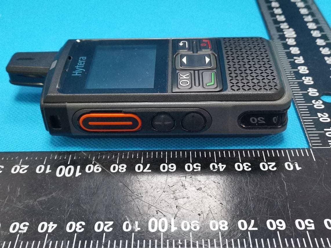
YAMPNC360S
Jan 19, 2022PoC Radio
Equipment Class
DTS - Digital Transmission System
YAMHM78XUVS
Jul 28, 2021DIGITAL MOBILE RADIO
Equipment Class
TNB - Licensed Non-Broadcast Station Transmitter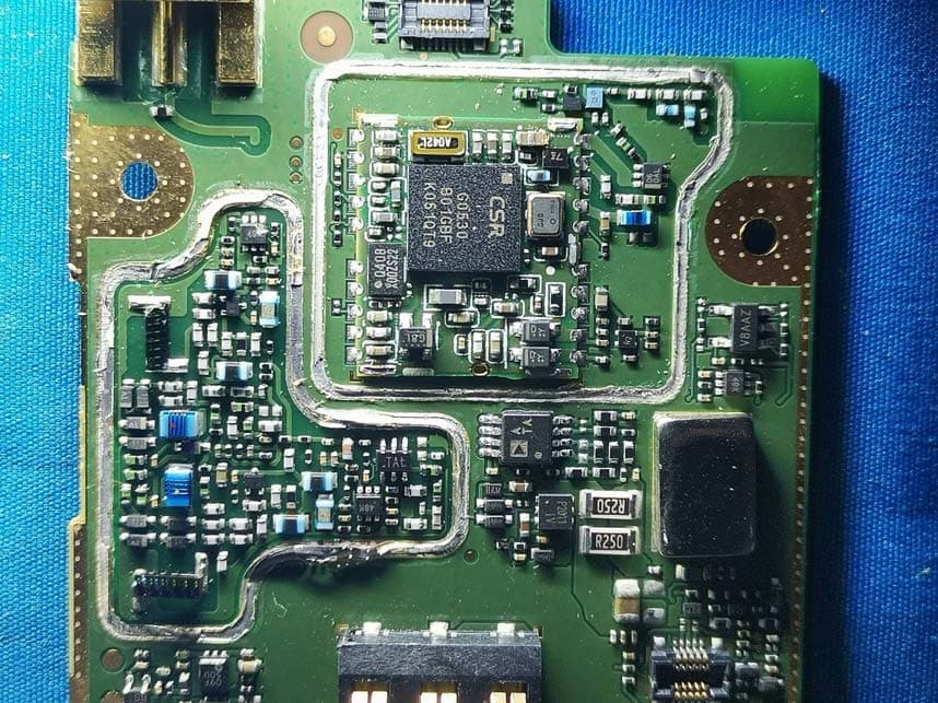
YAMHP6XXUMS
Jul 22, 2021Digital Portable Radio
Equipment Class
DTS - Digital Transmission System
YAMBD50XU1S
Jun 04, 2021DIGITAL PORTABLE RADIO
Equipment Class
TNF - Licensed Non-Broadcast Transmitter Held to Face