YBN-CCD-PROLINE3Car Radio with Bluetooth
Robert Bosch GmbH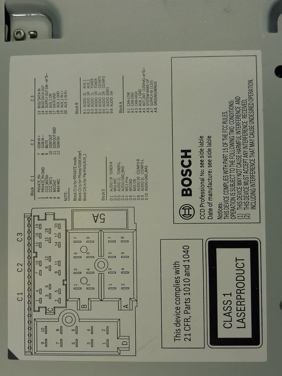
Click to zoom
Application Details
- Equipment Class
- DSS - Part 15 Spread Spectrum Transmitter
- Date of Grant
- May 15, 2012
- Application Purpose
- Original Equipment
- Date of Application
- May 14, 2012
- Equipment Note
- Car Radio with Bluetooth
- Frequency Range
- 2402.00000000 - 2480.00000000
- Company
- Robert Bosch GmbH
- Country
- Germany
Documents & Files
Document Text
Text extracted from the exhibit documents filed with the FCC. Open a document above to read the original.
Users Manual
Professional Line 3 CCD/CCS/CPA de Kurzanleitung en Operating instructions fr Mode d’emploi es Instrucciones de manejo it Istruzioni d’uso pt Instruções de serviço nl Gebruiksaanwijzing dk Betjeningsvejledning sw Bruksanvisning sf Käyttöohje pl Instrukcja obsługi tr Kullanım kılavuzu 01_ProLine3_de.indd 123.02.12 18:35 2 02.2012Robert Bosch Car Multimedia GmbH 13 1243 16 172523201922 121514 242118 911105786 01_ProLine3_de.indd 223.02.12 18:35 de | 3 02.2012Robert Bosch Car Multimedia GmbH de 1 ON-Taste Ein-/Ausschalten des Systems 2 CD-Schacht des CCD 3 Display 4 CD-Auswurftaste (Laufwerk des CCD) 5 AM-Taste Auswahl der Wellenbereiche MW, LW, SW (Europa) bzw. AM (NAFTA, LAM, ASIA) 6 -Taste Gespräch über Bluetooth®-Mobiltelefon beenden Für Geräte ohne Bluetooth®: >>-Taste Sendersuchlauf starten 7 TA-Taste Kurzdruck: Vorrang für Verkehrsmel- dungen ein-/ausschalten, durchgeschal- tete Verkehrsmeldung abbrechen Langdruck: Travelstore-Funktion starten 8 Stationstasten 1 - 6 Kurzdruck: Gespeicherten Sender wählen Langdruck: Sender speichern 9 SCRL-Taste Displayinhalt als Laufschrift anzeigen : -Taste Kurzdruck: Gespräch über Bluetooth®- Mobiltelefon annehmen, ausgewählten Teilnehmer anrufen Langdruck: Telefonbuch öffnen Für Geräte ohne Bluetooth®: <<-Taste Sendersuchlauf starten ; FM-Taste Auswahl der Wellenbereiche FM und WB (nur NAFTA), Wechsel zwischen den Speicherebenen FMTS, FM1, FM2 und WB (nur NAFTA) < Linker Dreh-/Drückknopf für den Cockpit-Bereich Drehen: Einstellen der Lautstärke und der Menü-Auswahl. Drücken: Öffnen und Bestätigen von Menüpunkten = DVD/CD-Schacht des CCS > Remote-Tasten ? Rechter Dreh-/Drückknopf für den Cabin-Bereich Drehen: Einstellen der Lautstärke und der Menü-Auswahl. Drücken: Öffnen und Bestätigen von Menüpunkten @ DVD/CD-Auswurftaste (Laufwerk des CCS) A Quellentasten (Cabin) RADIO: Auswahl der Audioquelle Radio für den Cabin-Bereich CD: Auswahl der Audioquelle CD für den Cabin-Bereich (Laufwerk des CCD) AUX: Auswahl der Audioquellen USB und AUX für den Cabin-Bereich VIDEO: Auswahl der Videoquelle für den Cabin-Bereich (Laufwerk des CCS und externe Videoquellen) Bedienelemente 01_ProLine3_de.indd 323.02.12 18:35 4 | de 02.2012Robert Bosch Car Multimedia GmbH Bedienelemente B MAP-Taste Anzeigen der Navigationskartendarstel- lung im Cabin-Bereich (nur bei ange- schlossener Coach Navigation in Verbin- dung mit einem geeigneten Fahrermonitor) C MON-Taste Aktivieren, Deaktivieren bzw. Sychronisie- ren der Monitore im Cabin-Bereich D MENU-Taste Aufrufen des Hauptmenüs zur Einstellung der Gerätegrundfunktionen E ESC-Taste Verlassen von Menüs F ENTER-Taste Bestätigungsfunktion im Navigations-, Video-, DVD- und TV-Betrieb G NAVI-Taste Aktiviert die Steuerung eines angeschlos- senen Navigationssystems über: fRemote-Tasten > fENTER-Taste F wie bei der Fernbedienung des Navigati- onssystems H CAM-Taste Auswahl eines Kamerabildes auf dem Fahrermonitor I Quellentasten (Cockpit) RADIO: Auswahl der Audioquelle Radio für das Cockpit CD: Auswahl der Audioquelle CD für das Cockpit (Laufwerk des CCD) AUX: Auswahl der Audioquellen USB und AUX für das Cockpit VIDEO: Auswahl der Videoquelle für das Cockpit (Laufwerk des CCS und externe Videoquellen) 01_ProLine3_de.indd 423.02.12 18:35 de | 5 02.2012Robert Bosch Car Multimedia GmbH de Inhaltsverzeichnis Inhaltsverzeichnis 17 CD/DVD einlegen/entfernen 17 Radiobetrieb 17 Verfügbare Wellenbereiche und Speicherebenen 18 Funktionen am CCS 19 Funktionen am CCD 20 Funktionen im Menü 21 Funktionen im Hauptmenü 22 CD- und USB-Betrieb 22 Funktionen am CCS 23 Funktionen im CD-/MP3-/WMA-Menü 24 Video- und DVD-Betrieb 24 Funktionen am CCS 25 Funktionen im Video-/DVD-Menü 26 DVD-Einstellungen im Hauptmenü 27 TV-Betrieb 27 Funktionen am CCS 27 Funktionen im TV-Menü 27 Display-Einstellungen 27 Funktion am CCD 28 Einstellungen im Hauptmenü 28 Monitor-Einstellungen 28 Funktionen am CCS 29 Einstellungen im Hauptmenü 7 Hinweise und Zubehör 7 Bestimmungsgemäßer Gebrauch 7 Altgerät-Entsorgung 8 Anschluss von Zusatzgeräten (Option) 9 Ein-/Ausschalten 9 Funktionen wählen und Einstel- lungen vornehmen 9 Direktanwahl 10 Im Menü 10 Bedienfokus 11 Audio-/Videoquelle wählen 11 Audio-/Videoquelle für das Cockpit wählen 12 Audio-/Videoquelle für den Cabin- Bereich wählen 13 Lautstärke und Klang einstellen 13 Lautstärke für die aktuelle Wieder- gabe einstellen 13 Grundlautstärken für unterschied- liche Quellen im Hauptmenü einstellen 14 Klang für die aktuelle Wiedergabe einstellen 14 Klangprofil speichern 15 Lautstärke und Klang für Mikrofon- durchsagen 15 Lautstärke und Klang für externe Durchsagen und Alarm (Fahrwarner) 16 Lautstärkepegel für verschiedene Audio-/Videoquellen anpassen 01_ProLine3_de.indd 523.02.12 18:35 6 | de 02.2012Robert Bosch Car Multimedia GmbH Inhaltsverzeichnis 29 Kamerafunktionen am CCS 29 Navigationsfunktionen am CCS 30 Bluetooth-Telefon-Funktionen 31 Funktionen am CCD 31 Bluetooth®-Einstellungen im Hauptmenü 32 Funktionen im Telefonbuch 32 MAS-Einstellungen 32 MAS-Einstellungen im Hauptmenü 33 Weitere Systemeinstellungen 34 Fernbedienung 35 Technische Daten 35 CCS 35 CCD 36 Coach Power Amplifier CPA 811 / CPA 2011 01_ProLine3_de.indd 623.02.12 18:35 de | 7 02.2012Robert Bosch Car Multimedia GmbH de Hinweise und Zubehör Bevor Sie Ihr Gerät in Betrieb nehmen, lesen Sie diese Anleitung sorgfältig und machen Sie sich mit dem Gerät vertraut. Bewahren Sie diese Anleitung für spätere Fragen im Fahrzeug auf. Bestimmungsgemäßer Gebrauch Der Einbau des CCS bzw. CCD erfolgt jeweils in einem 1 DIN-Schacht im Armaturenbrett eines Busses. Die Stromversorgung von CCS und CCD erfolgt ausschließlich über den CPA. Die Betriebsspannung am CPA beträgt 24 V. Der Einbau des CPA erfolgt fahrzeugabhängig abgesetzt vom Armaturenbrett. Verkehrssicherheit Die Verkehrssicherheit ist oberstes Gebot. fBedienen Sie das Gerät nur, wenn es die Verkehrslage zulässt. fMachen Sie sich vor Fahrtantritt mit dem Gerät vertraut. Akustische Warnsignale von Polizei, Feuerwehr …
Text truncated - open the document above for the full version.
Users Manual
138 | es 02.2012Robert Bosch Car Multimedia GmbH Coach Power Amplifier CPA 811 / CPA 2011 Tensión de empleo: + 24 V Consumo de corriente: en standby: < 500 �A incl. CCD y CCS máx. CPA 811: aprox. 10 A incl. CCD y CCS máx. CPA 2011: aprox. 15 A incl. CCD y CCS* * I máx. sin unidades periféricas Potencia de salida nominal Salpicadero: 2 x 20 W / = 4 ohmios Cabina (CPA 811): 2 x 20 W / = 4 ohmios Cabina (CPA 2011): 4 x 40 W / = 4 ohmios Respuesta: 40 Hz - 25 000 Hz Entradas EXTERN Audio (sólo salpicadero) CPA 811, CPA 2011: WARNER 2 V, NAVIGATION 2 V Todas las entradas lógicas EXTERN: Active Low Salidas de tensión: Switch Line Out (Subwoofer): 24 V / 0,4 A máx. MIC: 24 V / 1,3 A máx. VIDEO 1, 2: 24 V / 0,4 A máx. Otras entradas y salidas: Line Out, regulada Peso: CPA 811: aprox. 1,8 kg CPA 2011: aprox. 1,9 kg Normas: E1, FCC, CE, WEEE, ROHS BOSCH Professional Line 3 CCD/CCS/CPA FCC-ID: YBN-CCD-PROLINE3 IC: 9595A-CCDPROLINE3 MODELO: CCD PROFESSIONAL(BT) FCC §15.21: Los cambios o modificaciones que no hayan sido aprobados expresamente por la parte responsable del cumplimiento podrían anular la autoridad del usuario para utilizar el equipo. FCC §15.19: Este aparato cumple con el apartado 15 de las normas de la FCC y con los estándares RSS exentos de licencia de Industry Canada. El funcionamiento está sujeto a las dos condicio- nes siguientes: (1) Este aparato no debe causar interferencias prejudiciales. (2) Este aparato debe aceptar cualquier interferencia recibida, incluyendo interferen- cias que pudieran causar un funcionamiento no deseado. Robert Bosch Car Multimedia GmbH 02.2012 ¡Salvo modificaciones! Datos técnicos 04_ProLine3_es.indd 13823.02.12 18:38 it | 139 02.2012Robert Bosch Car Multimedia GmbH it 1 Tasto ON Accendere/spegnere il sistema 2 Vano CD del CCD 3 Display 4 Tasto espulsione CD (drive del CCD) 5 Tasto AM Selezione delle gamme di lunghezze d'onda OM, OL, OC (Europa) e AM (NAFTA, LAM, ASIA) 6 Tasto Concludere telefonata con cellulare Bluetooth® Per dispositivi senza Bluetooth®: Tasto >> Avviare la ricerca di stazioni radio 7 Tasto TA Premuto brevemente: accendere/ spegnere la priorità agli annunci sul traffico, interrompere un messaggio sul traffico Premuto a lungo: avviare la funzione Travelstore 8 Tasti stazioni 1 - 6 Premuto brevemente: selezionare le stazioni memorizzate Premuto a lungo: memorizzare le stazioni 9 Tasto SCRL Mostra il contenuto del display come testo scorrevole : Tasto Premuto brevemente: accettare una telefonata con cellulare Bluetooth®, chiamare un utente selezionato Premuto a lungo: aprire la rubrica telefonica Per dispositivi senza Bluetooth®: Tasto << Avviare la ricerca di stazioni radio ; Tasto FM Selezione delle gamme di lunghezza d'onda FM e WB (solo NAFTA), passaggio tra i livelli di memoria FMTS, FM1, FM2 e WB (solo NAFTA) < Pulsante/manopola sinistro per l'area Cockpit Girare: impostare il volume e la selezione menu. Premere: aprire e confermare le voci del menu = Vano DVD/CD del CCS > Tasti Remote ? Pulsante/manopola destro per l'area Cabin Girare: impostare il volume e la selezione menu. Premere: aprire e confermare le voci del menu @ Tasto espulsione DVD/CD (drive del CCS) A Tasti sorgente (Cabin) RADIO: selezione della radio come sorgente audio per l'area Cabin CD: selezione del CD come sorgente audio per l'area Cabin (drive del CCD) AUX: selezione di USB e AUX come sorgenti audio per l'area Cabin VIDEO: selezione della sorgente video per l'area Cabin (drive del CCS e sorgenti video esterne) Comandi 05_ProLine3_iW.indd 13923.02.12 18:39 140 | it 02.2012Robert Bosch Car Multimedia GmbH Comandi B Tasto MAP Visualizzare la mappa di navigazione nell'area Cabin (solo con Coach Navigation collegato, in combinazione con un monitor adatto per il conducente) C Tasto MON Attivare, disattivare e sincronizzare i moni- tor nell'area Cabin D Tasto MENU Visualizzazione del menu principale per impostare le funzioni base del dispositivo E Tasto ESC Uscita dai menu F Tasto ENTER Funzione di conferma in modalità navigazione, video, DVD e TV G Tasto NAVI Attiva il comando di un sistema di navigazione collegato tramite: ftasti Remote > ftasto ENTER F come con il telecomando del sistema di navigazione H Tasto CAM Selezione di un'immagine della videoca- mera sul monitor del conducente I Tasti sorgente (Cockpit) RADIO: selezione della radio come sorgente audio per il Cockpit CD: selezione del CD come sorgente audio per il Cockpit (drive del CCD) AUX: selezione di USB e AUX come sorgenti audio per il Cockpit VIDEO: selezione della sorgente video per il Cockpit (drive del CCS e sorgenti video esterne) 05_ProLine3_iW.indd 14023.02.12 18:39 it | 141 02.2012Robert Bosch Car Multimedia GmbH it Indice Indice 153 Inserire/estrarre CD/DVD 153 Modalità radio 153 Gamme di lunghezze d'onda e livelli di memoria disponibili 154 Funzioni di CCS 155 Funzioni di CCD 156 Funzioni nel menu 157 Funzioni nel menu principale 158 Modalità CD e USB 158 Funzioni di CCS 159 Funzioni nel menu CD/MP3/WMA 160 Modalità video e DVD 160 Funzioni di CCS 161 Funzioni nel menu video/DVD 162 Impostazioni per il DVD nel menu principale 163 Modalità TV 163 Funzioni di CCS 163 Funzioni nel menu TV 163 Impostazioni del display 163 Funzioni di CCD 164 Impostazioni nel menu principale 164 Impostazioni del monitor 164 Funzioni di CCS 165 Impostazioni nel menu principale 143 Note e accessori 143 Impiego conforme alla destinazione 143 Smaltimento di apparecchi usati 144 Collegamento di dispositivi addizio- nali (opzione) 145 Accendere/spegnere 145 Selezionare le funzioni e eseguire le impostazioni 145 Selezione diretta 146 Nel menu 146 Focalizzazione dei comandi 147 Selezionare la sorgente audio/ video 147 Selezionare la sorgente audio/video per il Cockpit 148 Selezionare la sorgente audio/video per l'area Cabin 149 Impostare il volume e il suono 149 Impostare il volume per la riproduzi- one attuale 149 Impostare nel menu principale i volumi di base per le diverse sorgenti 150 Impostare il suono per la riprod…
Text truncated - open the document above for the full version.
Users Manual
sw | 275 02.2012Robert Bosch Car Multimedia GmbH sw 1 ON-knapp Aktivera/avaktivera systemet 2 Cd-fack på CCD 3 Display 4 Cd-utmatningsknapp (läsare på CCD) 5 AM-knapp Välja våglängdsområde MV, LV, KV (Europa) eller AM (NAFTA, LAM, ASIA) 6 -knapp Avsluta samtal via Bluetooth®- mobiltelefon För apparater utan Bluetooth®: >>-knapp Starta stationssökningen 7 TA-knapp Kort tryckning: Aktivera/avaktivera prioritet för trafikmeddelanden, avbryta framkopplat trafikmeddelande Lång tryckning: Starta Travelstore-funktio- nen 8 Stationsknappar 1 - 6 Kort tryckning: Välja sparad station Lång tryckning: Spara station 9 SCRL-knapp Visa displayinnehåll som löpande text : -knapp Kort tryckning: Svara i telefonen via Bluetooth®-mobiltelefon, ringa till vald samtalspartner Lång tryckning: Öppna telefonboken För apparater utan Bluetooth®: <<-knapp Starta stationssökningen ; FM-knapp Välja våglängdsområde FM och WB (bara NAFTA), växla mellan minnesnivåerna FMTS, FM1, FM2 och WB (bara NAFTA) < Vänster vrid-/tryckknapp för förarutrym- met Vrid: Ställa in volym och menyval Tryck: Öppna och bekräfta menypunkter = Dvd-/cd-fack på CCS > Remote-knappar ? Höger vrid-/tryckknapp för passagerarut- rymmet Vrid: Ställa in volym och menyval Tryck: Öppna och bekräfta menypunkter @ Dvd-/cd-utmatningsknapp (läsare på CCS) A Knappar för källan (passagerarutrymme) RADIO: Välja ljudkällan radio för passagerarutrymmet CD: Välja ljudkällan cd för passagerar- utrymmet (läsare på CCD) AUX: Välja ljudkällorna USB och AUX för passagerarutrymmet VIDEO: Välja videokällan för passagerar- utrymmet (läsare på CCS och externa videokällor) Reglage 09_ProLine3_sw.indd 27523.02.12 18:26 276 | sw 02.2012Robert Bosch Car Multimedia GmbH Bedienelemente B MAP-knapp Visning av navigationskartfönstret i passagerarutrymmet (bara om Coach Navigation är ansluten tillsammans med förarens skärm som då måste lämpa sig för detta) C MON-knapp Aktivera, avaktivera eller synkronisera skärmarna i passagerarutrymmet D MENU-knapp Anropa huvudmenyn för inställning av utrustningens grundfunktioner E ESC-knapp Lämna menyer F ENTER-knapp Bekräftelsefunktion i navigations-, video-, dvd- och tv-läge G NAVI-knapp Aktiverar regleringen av ett tillkopplat navigationssystem via: fremote-knappar > fENTER-knapp F som på fjärrkontrollen till navigationssys- temet H CAM-knapp Välja en kamerabild på förarens skärm I Källknappar (förarutrymme) RADIO: Välja radiokällan radio för förarutrymmet CD: Välja ljudkällan cd för förarutrym- met (läsare på CCD) AUX: Välja ljudkällorna USB och AUX för förarutrymmet VIDEO: Välja videokällan för förarutrym- met (läsare på CCS och externa videokällor) 09_ProLine3_sw.indd 27623.02.12 18:26 sw | 277 02.2012Robert Bosch Car Multimedia GmbH sw Innehållsförteckning Innehållsförteckning 289 Sätta i / Ta ut cd/dvd 289 Radioläge 289 Tillgängliga våglängdsområden och minnesnivåer 290 Funktioner på CCS 291 Funktioner på CCD 292 Funktioner i menyn 293 Funktioner i huvudmenyn 294 Cd- och USB-läge 294 Funktioner på CCS 295 Funktioner i CD-/MP3-/WMA-menyn 296 Video- och dvd-läge 296 Funktioner på CCS 297 Funktioner i video-/dvd-menyn 298 Dvd-inställningar i huvudmenyn 299 Tv-läge 299 Funktioner på CCS 299 Funktioner i tv-menyn 299 Displayinställningar 299 Funktion på CCD 300 Inställningar i huvudmenyn 300 Skärminställningar 300 Funktioner på CCS 301 Inställningar i huvudmenyn 279 Information och tillbehör 279 Avsedd användning 279 Avfallshantering av uttjänta apparater 280 Anslutning av extrautrustningar (tillval) 281 Slå på/av 281 Välja funktioner och göra inställ- ningar 281 Direktval 282 I menyn 282 Manöverfokus 283 Välja ljud-/videokälla 283 Välja ljud-/videokälla för förarutrym- met 284 Välja ljud-/videokälla för förarutrym- met 285 Ställa in volym och ljudbild 285 Ställa in volymen för aktuell uppspel- ning 285 Ställa in grundvolymerna för olika källor i huvudmenyn 286 Ställa in ljudbilden för aktuell uppspelning 286 Spara ljudbildsprofil 287 Volym och ljudbild för meddelanden i mikrofon 287 Volym och ljudbild för externa meddelanden och larm (varningssy- stem för föraren) 288 Anpassa nivån på volymen för olika ljud-/videokällor 09_ProLine3_sw.indd 27723.02.12 18:26 278 | sw 02.2012Robert Bosch Car Multimedia GmbH Innehållsförteckning 301 Kamerafunktioner på CCS 301 Navigationsfunktioner på CCS 302 Bluetooth-telefon-funktioner 303 Funktioner på CCD 303 Bluetooth®-inställningar i huvudme- nyn 304 Funktioner i telefonboken 304 MAS-inställningar 304 MAS-inställningar i huvudmenyn 305 Fler systeminställningar 306 Fjärrkontroll 307 Tekniska data 307 CCS 307 CCD 308 Coach Power Amplifier CPA 811 / CPA 2011 09_ProLine3_sw.indd 27823.02.12 18:26 sw | 279 02.2012Robert Bosch Car Multimedia GmbH sw Information och tillbehör Läs denna bruks- och monteringsanvisning noggrant och bekanta dig med apparaten innan du tar den i bruk. Spara bruksanvisningen i fordonet för eventuella framtida frågor. Avsedd användning CCS respektive CCD monteras in i ett 1 DIN-fack i instrumentbrädan i en buss. Strömförsörjningen till CCS och CCD sker alltid via CPA. CPA har 24 V driftspänning. CPA monteras inte i instrumentbrädan utan på en annan lämplig plats, beroende på fordonet. Trafiksäkerhet Trafiksäkerheten måste alltid gå före allt annat. fAnvänd endast apparaten när trafiksituationen tillåter det. fBekanta dig med apparaten innan du börjar köra. Du ska kunna uppfatta ljudsignaler från utryckningsfordon tydligt och i tillräckligt god tid i fordonet. fAnpassa volymen därefter under färd. Avfallshantering av uttjänta appa- rater Släng aldrig en uttjänt apparat i hushållssoporna! Lämna den uttjänta apparaten till ett återvinnings- eller insamlingsställe. Information och tillbehör 09_ProLine3_sw.indd 27923.02.12 18:26 280 | sw 02.2012Robert Bosch Car Multimedia GmbH Information och tillbehör Anslutning av extrautrustningar (tillval) CCS (Coach Control System) är den centrala manöverenheten till Coach Professional Line 3 och med den går det att ställa in och reglera ljud- och bil…
Text truncated - open the document above for the full version.
External Photos
ANNEX B: EXTERNAL PHOTOGRAPHS Test engineer:Thomas KÜHNReport Number:F110734E2, 2 nd version Dateof issue:13 April 2012Order Number:110734page1 of 4 110734_f.jpgCCD, 3D view 1 ANNEX B: EXTERNAL PHOTOGRAPHS Test engineer:Thomas KÜHNReport Number:F110734E2, 2 nd version Dateof issue:13 April 2012Order Number:110734page2 of 4 110734_g.jpgCCD, 3D view 2 ANNEX B: EXTERNAL PHOTOGRAPHS Test engineer:Thomas KÜHNReport Number:F110734E2, 2 nd version Dateof issue:13 April 2012Order Number:110734page3 of 4 110734_i.jpgCCD, type plate 1 ANNEX B: EXTERNAL PHOTOGRAPHS Test engineer:Thomas KÜHNReport Number:F110734E2, 2 nd version Dateof issue:13 April 2012Order Number:110734page4 of 4 110734_h.jpgCCD, type plate 2
Internal Photos
ANNEX C: INTERNAL PHOTOGRAPHS Testengineer:Thomas KÜHNReport Number:F110734E2, 2 nd versioin Date of issue:13 April 2012Order Number:110734page1 of 7 110734_d.jpgSwitch PCB, rear view ANNEX C: INTERNAL PHOTOGRAPHS Testengineer:Thomas KÜHNReport Number:F110734E2, 2 nd versioin Date of issue:13 April 2012Order Number:110734page2 of 7 110734_e.jpgSwitch PCB, front view ANNEX C: INTERNAL PHOTOGRAPHS Testengineer:Thomas KÜHNReport Number:F110734E2, 2 nd versioin Date of issue:13 April 2012Order Number:110734page3 of 7 110734_l.jpgSwitch PCB, rear view, detail view to Bluetooth unit ANNEX C: INTERNAL PHOTOGRAPHS Testengineer:Thomas KÜHNReport Number:F110734E2, 2 nd versioin Date of issue:13 April 2012Order Number:110734page4 of 7 110734_o.jpgSwitch PCB, rear view, detail view to Bluetooth unit, housing removed ANNEX C: INTERNAL PHOTOGRAPHS Testengineer:Thomas KÜHNReport Number:F110734E2, 2 nd versioin Date of issue:13 April 2012Order Number:110734page5 of 7 110734_k.jpgSwitch PCB, rear view, detail view to Bluetooth unit (sample with temporary antenna connector) ANNEX C: INTERNAL PHOTOGRAPHS Testengineer:Thomas KÜHNReport Number:F110734E2, 2 nd versioin Date of issue:13 April 2012Order Number:110734page6 of 7 110734_n.jpgALPS evaluation board, top view ANNEX C: INTERNAL PHOTOGRAPHS Testengineer:Thomas KÜHNReport Number:F110734E2, 2 nd versioin Date of issue:13 April 2012Order Number:110734page7 of 7 110734_m.jpgALPS evaluation board, bottom view
Test Report
ANNEX DRESULTS OF THE RECEIVER MEASUREMENTS Test engineer:Thomas KÜHNReport Number:F110734E2, 2 nd version Date of issue:13 April 2012Order Number:110734page1 of 6 1 RADIATED EMISSIONS (RECEIVER) 1.1Preliminary radiated emission measurement (9 kHz to 1 GHz) Ambient temperature21 °CRelative humidity38 % Position of EUT:The EUT was set-up on a non-conducting table of a height of 0.8 m. The distance between EUT andantenna was 3 m. Cable guide:The cable of the EUT is running vertically to the false floor. For detail information of test set-up and the cable guide refer to the pictures in annex A of this test report. Test record:All results are shown in the following. The method of measurement is described in subclause 5.7.1 of the test report. Supply voltage:During all measurements the EUT was supplied with 12.0 V DC. 110734_36.wmf: Spurious emissions from 9 kHz to 150 kHz (operation mode 5): A 1MAX1MA RFAtt0dBRBW200Hz SWT18s VBW200Hz 1MA IN1 RefLvl 70dBμV RefLvl 70dBμVUnitdBμV Start9kHzStop150kHz14.1kHz/ P0 -20 -10 0 10 20 30 40 50 60 -30 70 TEST EQUIPMENT USED FOR THE TEST: 29, 31– 35, 43, 55 ANNEX DRESULTS OF THE RECEIVER MEASUREMENTS Test engineer:Thomas KÜHNReport Number:F110734E2, 2 nd version Date of issue:13 April 2012Order Number:110734page2 of 6 110734_37.wmf: Spurious emissions from 150 kHz to 1 MHz (operation mode 5): A 1MAX1MA UnitdB V Ref Lvl 70 dB V Ref Lvl 70 dB V RF Att0 dB P0 Start 150 kHzStop 1 MHz85 kHz/ RBW10 kHz VBW10 kHz SWT 21.5 ms 1MA IN1 -20 -10 0 10 20 30 40 50 60 -30 70 Date:15.MAR.2011 16:30:27 110734_38.wmf: Spurious emissions from 1 MHz to 30 MHz (operation mode 5): A 1MAX1MA UnitdBμV RefLvl 70dBμV RefLvl 70dBμV RFAtt0dB P0 Start1MHzStop30MHz2.9MHz/ RBW10kHz VBW10kHz SWT1.1s 1MA IN1 -20 -10 0 10 20 30 40 50 60 -30 70 No significant frequencies above the noise floor of the system were found during the preliminary radiated emission test, so no measurements were carried out on the outdoor test site. ANNEX DRESULTS OF THE RECEIVER MEASUREMENTS Test engineer:Thomas KÜHNReport Number:F110734E2, 2 nd version Date of issue:13 April 2012Order Number:110734page3 of 6 110734_39.wmf: Spurious emissions from 30 MHz to 230 MHz (operation mode 5): A UnitdBμV/m RBW100kHz VBW100kHz SWT110ms RFAtt0dB IN1 1MA RefLvl 70dB* RefLvl 70dB* Start30MHzStop230MHz20MHz/ P20 TDF 1MAX1MA -20 -10 0 10 20 30 40 50 60 -30 70 110734_40.wmf: Spurious emissions from 230 MHz to 1 GHz (operation mode 5): 1MAX RefLvl 70dB* RefLvl 70dB* RBW100kHz VBW100kHz SWT195ms RFAtt0dB A IN1 1MA1MA UnitdBμV/m Start230MHzStop1GHz77MHz/ P20 TDF -20 -10 0 10 20 30 40 50 60 -30 70 No significant frequencies above the noise floor of the system were found during the preliminary radiated emission test, so no measurements were carried out on the open area test site. ANNEX DRESULTS OF THE RECEIVER MEASUREMENTS Test engineer:Thomas KÜHNReport Number:F110734E2, 2 nd version Date of issue:13 April 2012Order Number:110734page4 of 6 1.2Preliminary radiated emission measurement (1 GHz to 12.5 GHz) Ambient temperature21 °CRelative humidity38 % Position of EUT:The EUT was set-up on a non-conductingtable of a height of 0.8 m. The distance between EUT and antenna was 3 m. Cable guide:The cable of the EUT is running vertically to the false floor. For detail information of test set-up and the cable guide refer to the pictures in annex A of this test report. Test record:All results are shown in the following. Supply voltage:During all measurements the EUT was supplied with 12.0 V DC. 110734_35.wmf: Spurious emissions from 1 GHz to 4 GHz (operation mode 5): UnitdBμV 1MAX A 1MA P0 Start1GHzStop4GHz300MHz/ RefLvl 70dBμV RefLvl 70dBμV RBW100kHz VBW100kHz SWT760ms RFAtt0dB 1MA IN1 -20 -10 0 10 20 30 40 50 60 -30 70 ANNEX DRESULTS OF THE RECEIVER MEASUREMENTS Test engineer:Thomas KÜHNReport Number:F110734E2, 2 nd version Date of issue:13 April 2012Order Number:110734page5 of 6 110734_34.wmf: Spurious emissions from 4 GHz 12.5 GHz (operation mode 5): UnitdBμV 1MAX A P0 1MA Start4GHzStop12.5GHz850MHz/ RefLvl 70dBμV RefLvl 70dBμV RBW100kHz VBW100kHz SWT2.15s RFAtt0dB 1MA IN1 -20 -10 0 10 20 30 40 50 60 -30 70 The following frequencies were found during the preliminary radiated emission measurement: -1.628 GHz and 3.482 GHz. These frequencies have to be measured in a final measurement. The result is presented in the following. TEST EQUIPMENT USED FOR THE TEST: 29, 31– 34, 36, 44, 49 ANNEX DRESULTS OF THE RECEIVER MEASUREMENTS Test engineer:Thomas KÜHNReport Number:F110734E2, 2 nd version Date of issue:13 April 2012Order Number:110734page6 of 6 1.3Final radiated emission measurement (1 GHz to 12.5 GHz) Ambient temperature21 °CRelative humidity38 % Position of EUT:The EUT was set-up on a non-conducting table of a height of 0.8 m. The distance between EUT and antenna was 3 m. Cable guide:The cable of the EUT is running vertically to the false floor. For detail information of test set-up and the cable guide refer to the pictures in annex A of this test report. Test record:All results are shown in the following. The method of measurement is described in subclause 5.2.1 of the test report. Supply voltage:During all measurements the EUT was supplied with 12.0 V DC. Remark:Where not otherwise stated the test was carried out in test mode 5 of the EUT. Result measured with the peak detector: Result measured with the average detector: Test result:Passed TEST EQUIPMENT USED FOR THE TEST: 29, 31– 34, 36, 44, 49 Frequency GHz Corr. value dBμV/m Limit dBμV/m Margin dB Readings dBμV Antenna factor 1/m Preamp dB Cable loss dB Height cm Pol. 1.62837.674.036.435.625.426.53.1150Vert. 3.48245.874.028.236.531.126.34.5150Vert. Measurement uncertainty+2.2 dB /-3.6 dB Frequency GHz Corr. value dBμV/m Limit dBμV/m Margin dB Readings dBμV Antenna factor 1/m Preamp dB Cable loss dB Height cm Pol. 1.62829.554.024.527.525.426.53.1150Vert. 3.48237.354.016.728.031.126.34.5150Vert. Measurement uncertainty+2.2 dB /-3.6 dB
Test Report
Königswinkel 10 32825 Blomberg Germany Phone:+49 (0) 52 35 95 00-0 Fax:+49 (0) 52 35 95 00-10 Test Report Report Number: F110734E2, 2 nd version Applicant: Robert Bosch Car Multimedia GmbH Manufacturer: Robert Bosch Car Multimedia GmbH Equipment under Test (EUT): CCD PROFESSIONAL(BT) Article number: 7 620 200 026 Laboratory (CAB) accredited by Deutsche Gesellschaft für Akkreditierung mbH in compliance with DIN EN ISO/IEC 17025 under the Reg. No. DGA-PL-105/99-22, FCC Test site registration number 90877and Industry Canada Test site registration IC3469A-1 Test engineer:Thomas KÜHNReport Number:F110734E2, 2 nd version Date of issue:13 April 2012Order Number:110734page2 of49 REFERENCES [1]ANSI C63.4-2009American National Standard for Methods of Measuring of Radio-Noise Emissions from Low-Voltage Electrical and Electronic Equipment in the Range of 9 kHz to 40 GHz. [2]FCC CFR 47 Part 15 (October 2009)Radio Frequency Devices [3]FCC Public Notice DA 00-705 (March 2000) [4]RSS-210 Issue 8 (December 2010)Licence-exempt Radio Apparatus (All Frequency Bands): Category I Equipment [5]RSS-GenIssue 3 (December 2010)General Requirements and Information for the Certification of Radio Apparatus [6]Publication Number 913591 (March 2007)Measurement of radiated emissions at the edge of the band for a Part 15 RF Device TEST RESULT The requirements of the tests performed as shown in the overview (clause4) werefulfilled by the equipment under test. The complete test results are presented in the following. RESERVATION T h i s t e s t r e p o r t i s o n l y v a l i d i n i t s o r i g i n a l f o r m . Any reproduction of its contents in extracts without written permission of the accredited test laboratory PHOENIX TESTLAB GmbH is prohibited. The test resultsherein refer only to the tested sample. PHOENIX TESTLAB GmbH is not responsible for any generalisations or conclusions drawn from these test results concerning further samples. Any modification of the tested samples is prohibited and leads to the invalidity of this test report. Each page necessarily contains the PHOENIX TESTLAB Logo and the TEST REPORT NUMBER. Test engineer: Thomas KÜHN13 April 2012 NameSignatureDate Authorized reviewer: Bernd STEINER13 April 2012 Name Signature Date Test engineer:Thomas KÜHNReport Number:F110734E2, 2 nd version Date of issue:13 April 2012Order Number:110734page3 of49 Contents:Page 1IDENTIFICATION.....................................................................................................................................4 1.1Applicant.............................................................................................................................................4 1.2Manufacturer.......................................................................................................................................4 1.3Test laboratory....................................................................................................................................4 1.4EUT (Equipment Under Test).............................................................................................................5 1.5Technical data of equipment...............................................................................................................5 1.6Dates...................................................................................................................................................5 2OPERATIONAL STATES.........................................................................................................................6 3ADDITIONAL INFORMATION.................................................................................................................7 4OVERVIEW..............................................................................................................................................7 5TEST RESUL…
Text truncated - open the document above for the full version.
Contact Information
Applicant
Dirk Zamow(Team Manager Approval)
Test Firm
PHOENIX TESTLAB GmbHHolger Bentje
Technical Specifications
| # | Rule Parts | Frequency Range | Power Output |
|---|---|---|---|
| 1 | 15C | 2.40 GHz - 2.48 GHz | 1.00 mW |
Other Applications from Robert Bosch GmbH
YBN-LCN2K58A10
Aug 25, 2015Radio Navigation System
Equipment Class
DSS - Part 15 Spread Spectrum TransmitterYBN-LCN2K70A10
Aug 25, 2015Radio Navigation System
Equipment Class
DSS - Part 15 Spread Spectrum Transmitter
YBN-LCN2K70B10
Aug 25, 2015Radio Navigation System
Equipment Class
DSS - Part 15 Spread Spectrum Transmitter
YBN-LCN2K70C10
Aug 25, 2015Radio Navigation System
Equipment Class
DSS - Part 15 Spread Spectrum Transmitter
YBN-AU-FPK10
Feb 15, 2015Instrument cluster
Equipment Class
DXX - Part 15 Low Power Communication Device Transmitter