Text extracted from the exhibit documents filed with the FCC. Open a document above to read the original.
Manual SenzaBlock SB110-NTC E-Senza Technologies GmbH | Bücklestr. 82b | 78467 Konstanz | Germany Tel.: +49 7531 36599- 10, Fax: +49 7531 36599-29 | [email protected] | www.e-senza.de Doc V1.6 Leveraging Power of Wireless ® General Information Notice: This device complies with part 15 of the FCC Rules and with RSS-210 of Industry Canada. Operation is subject to the following two conditions: (1) This device may not cause harmful interference, and (2) this device must accept any interference received, including interference that may cause undesired operation. Notice: Changes or modifications made to this equipment not expressly approved by E-Senza Technologies may void the FCC authorization to operate this equipment. This includes but is not limited to modifications of the antenna or use of an antenna not approved by E-Senza Technologies. Note: This equipment has been tested and found to comply with the limits for a Class B digital device, pursuant to part 15 of the FCC Rules. These limits are designed to provide reasonable protection against harmful interference in a residential installation. This equipment generates, uses and can radiate radio frequency energy and, if not installed and used in accordance with the instructions, may cause harmful interference to radio communications. However, there is no guarantee that interference will not occur in a particular installation. If this equipment does cause harmful interference to radio or television reception, which can be determined by turning the equipment off and on, the user is encouraged to try to correct the interference by one or more of the following measures: - Reorient or relocate the receiving antenna. - Increase the separation between the equipment and receiver. - Connect the equipment into an outlet on a circuit different from that to which the receiver is connected. - Consult the dealer or an experienced radio/TV technician for help. Radiofrequency radiation exposure Information: The radiated output power of the device is far below the FCC radio frequency exposure limits. Nevertheless, the device shall be used in such a manner that the potential for human contact during normal operation is minimized. Leveraging Power of Wireless ® Safety Information In order to ensure the safe use of the product described, you have to read and understand this manual. The following notes provide information on how to use this manual. Explanation of symbols used and signal words The following types of messages provide information about possible property damage and general information concerning proper operation and ease-of-use. The following types of messages provide information about possible property damage and general information concerning proper operation and ease-of-use. SenzaBlock is ESD sensitive ! • Prevent SenzaBlock OEM module or PCB inside the enclosure from touching your clothing. Most clothing is insulative and retains a charge even when you are wearing a wrist strap. • Wear a grounded wrist strap against your skin to eliminate static on your body • Hold SenzaBlock by its enclosure or its edge. If you are removing a pluggable module, use the correct tool. User group of this manual The use of products described in this manual is oriented exclusively to – qualified electricians or persons instructed by them, who are familiar with applicable standards and other regulations regarding electrical engineering and, in particular, the relevant safety concepts. – qualified application programmers and software engineers, who are familiar with the safety concepts of automation technology and applicable standards. E-Senza Technologies accepts no liability for erroneous handling or damage to products from E- Senza Technologies or third-party products resulting from disregard of information contained in this manual. Battery Handling Guidelines • Insert the battery correctly (+/-). • Do not recharge • Do not open or dispose in fire • Do not heat above 100°C • Do not expose contents to water • Do not mix with used batteries or other battery types Not considering the above steps may lead to explosion, leaking of battery and can cause damage! This is the safety alert symbol. It is used to alert you to potential personal injury hazards. Obey all safety messages that follow this symbol to avoid possible injury or death. This symbol and the accompanying text alerts the reader to a situation which may cause damage or malfunction to the device, either hardware or software, or surrounding property. This symbol and the accompanying text provide additional information to the reader. It is also used as a reference to other sources of information (manuals, data sheets) on the subject matter, product, etc. Leveraging Power of Wireless ® Content 1 SenzaNET ................................................................................... 1 1.1 Communication in SenzaNET ...................................................... 1 1.2 Network Elements ................................................................... 2 1.2.1 SenzaBlock ............................................................................................. 2 1.2.2 Gateway ................................................................................................ 2 1.2.3 SenzaWMS .............................................................................................. 2 2 SenzaBlock SB110-NTC .................................................................... 2 2.1 Features .............................................................................. 2 2.2 Installation ........................................................................... 2 2.2.1 Mechanical Installation............................................................................... 2 2.2.1.1 Sensor Temperature Grade ..................................................................... 3 2.2.2 Electrical Installation................................................................................. 4 2.2.2.1 Connecting…
Text truncated - open the document above for the full version.
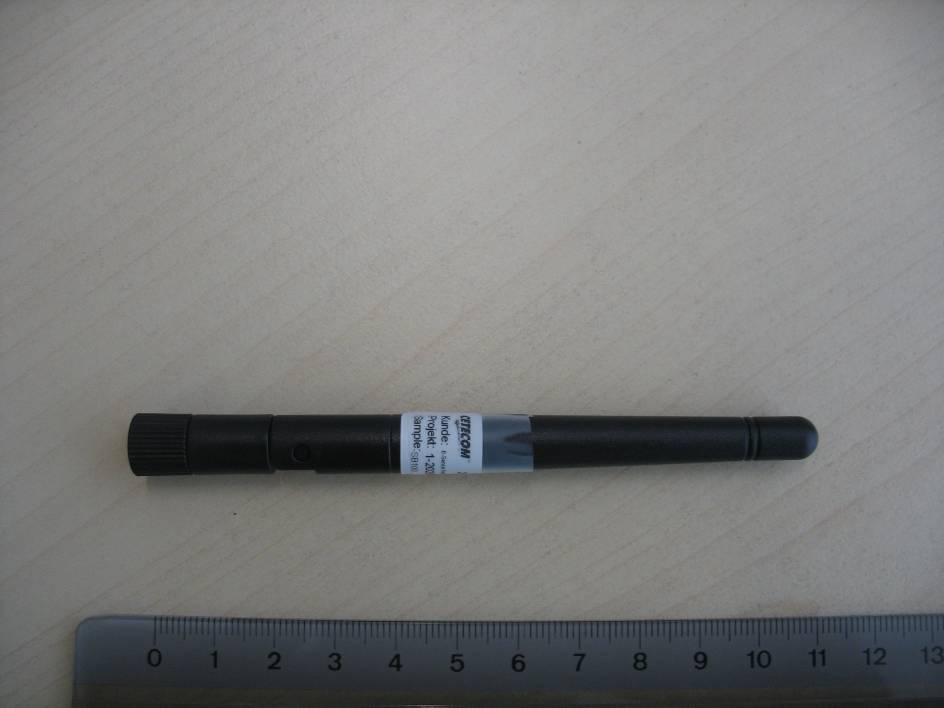
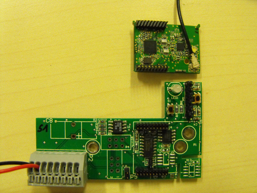
Test report no.: 1-2029-02-06/10-A 2011-02-18 Page 61 of 66 An n ex B P h o t o g rap h s o f t h e E UT Photo documentation Photo 1 Photo 2 Test report no.: 1-2029-02-06/10-A 2011-02-18 Page 62 of 66 Photo 3 Photo 4 Test report no.: 1-2029-02-06/10-A 2011-02-18 Page 63 of 66 Photo 5 Photo 6
Test report no.: 1-2029-02-06/10-A 2011-02-18 Page 64 of 66 Photo 7 Photo 8 Test report no.: 1-2029-02-06/10-A 2011-02-18 Page 65 of 66 Photo 9 Photo 10
2011-02-18 Page 1 of 66 TEST REPORT Test report no.: 1-2029-02-06/10-A Testing laboratory Applicant CETECOM ICT Services GmbH Untertuerkheimer Straße 6 – 10 66117 Saarbruecken / Germany Phone: + 49 681 5 98 - 0 Fax: + 49 681 5 98 - 9075 Internet: http://www.cetecom.com e-mail: [email protected] Accredited test laboratory: The test laboratory (area of testing) is accredited according to DIN EN ISO/IEC 17025 DAR registration number: DGA-PL-176/94-D1 Area of Testing: Radio/Satellite Communications E-Senza Technologies GmbH Buecklestrasse 82b 78467 Konstanz / Germany Phone: +49 (0) 7531 36599-10 Fax: +49 7531 36599 -29 Contact: Johannes Bleuel e-mail: [email protected] Phone: +49 7531 36599 -22 Manufacturer E-Senza Technologies GmbH Buecklestrasse 82b 78467 Konstanz / Germany Test standard/s 47 CFR Part 15 Title 47 of the Code of Federal Regulations; Chapter I-Federal Communications Commission subchapter A - general, Part 15-Radio frequency devices For further applied test standards please refer to section 3 of this test report. Test item Kind of test item: 2.4 GHz radio module with frequency hopping Model name: SB100-E FCC ID: YBSSB100-E IC: 9026A-SB100E Frequency [MHz]: 2400 – 2483.5 MHz ISM-band Ch11 (2405 MHz) to Ch26 (2480 MHz) Power supply: 3 V DC by battery Temperature range: -20 °C to 55 °C This test report is electronically signed and valid without handwriting signature. For verification of the electronical signatures, the public keys can be requested at the testing laboratory. Test performed: Test report authorised: Stefan Bös Frank Salvamoser Test report no.: 1-2029-02-06/10-A 2011-02-18 Page 2 of 66 1 Table of contents 1 Table of contents ................................................................................................................................2 2 General information ............................................................................................................................3 2.1 Notes .........................................................................................................................................3 2.2 Application details ....................................................................................................................3 3 Test standard/s ...................................................................................................................................3 4 Test environment ................................................................................................................................3 5 Test item .............................................................................................................................................4 6 Test laboratories sub-contracted ........................................................................................................4 7 Summary of measurement results ......................................................................................................5 8 RF measurement testing .....................................................................................................................6 8.1 Description of test setup ...........................................................................................................6 8.1.1 Radiated measurements ....................................................................................................6 8.1.2 Conducted measurements .................................................................................................7 8.2 Additional comments ................................................................................................................7 8.3 RSP100 test report cover sheet / performance test data ...........................................................8 9 Measurement results ...........................................................................................................................9 9.1 Antenna gain .............................................................................................................................9 9.2 Power spectral density ............................................................................................................ 10 9.3 Carrier frequency separation................................................................................................... 13 9.4 Number of hopping channels .................................................................................................. 15 9.5 Time of occupancy (dwell time)............................................................................................... 17 9.6 Spectrum bandwidth of a FHSS system – 20 dB bandwidth.................................................... 19 9.7 Maximum output power........................................................................................................... 22 9.8 Band edge compliance conducted .......................................................................................... 25 9.9 Band edge compliance radiated .............................................................................................. 29 9.10 TX spurious emissions conducted ...................................................................................... 32 9.11 TX spurious emissions radiated .......................................................................................... 37 9.12 RX spurious emissions radiated .......................................................................................... 49 9.13 TX spurious emissions radiated < 30 MHz ........................................................................... 54 9.14 TX spurious emissions conducted < 30 MHz ....................................................................... 56 10 Test equipment and ancillaries used for tests ............................................................................ 58 Annex A Photographs of the test setup...............................................................................…
Text truncated - open the document above for the full version.
Test report no.: 1-2029-02-06/10-A 2011-02-18 Page 60 of 66 An n ex A P h o t o g rap h s o f t h e t est set u p Photo documentation Photo 1 Photo 2
| # | Rule Parts | Frequency Range | Power Output |
|---|---|---|---|
| 1 | 15C | 2.40 GHz - 2.48 GHz | 14.00 mW |

2.4 GHz Module
Equipment Class
DSS - Part 15 Spread Spectrum Transmitter