Text extracted from the exhibit documents filed with the FCC. Open a document above to read the original.
Clarity Design 0125A 802.11b/g Module Operators Guide Clarity Design, Inc. Page 1 of 3 March 23, 2011 Clarity Design 0125A 802.11b/g Module Operators Guide FCC ID: YC7-0125A IC: 8962A-0125A 1 Overview The Clarity Design 0125A 802.11b/g Module is normally inserted into an available SD card slot that is controlled by an SD Slot host controller. 2 Operation Turn the module on or off: The module will be turned on and off under the control of the SD slot host controller. Initialization of the module: The module will be initialized and configured by the SD slot host controller once it is inserted into an SD card slot. The module will connect to an 802.11 b/g compatible device after configuration assuming there is one available for connection. 3 FCC Part 15 Information to User This device complies with Part 15 of the FCC Rules. Operation is subject to the following two conditions: (1) This device may not cause harmful interference, and (2) This device must accept any interference received, including interference that may cause undesired operation. This equipment has been tested and found to comply with the limits for Class B Digital Device, pursuant to Part 15 of the FCC Rules. These limits are designed to provide reasonable protection against harmful interference in a residential installation. This equipment generates and can radiate radio frequency energy and, if not installed and used in accordance with the instructions, may cause harmful interference to radio communications. However, there is no guarantee that interference will not occur in a particular installation. If this equipment does cause harmful interference to radio or television reception, which can be determined by turning the equipment off and on, the Clarity Design 0125A 802.11b/g Module Operators Guide Clarity Design, Inc. Page 2 of 3 March 23, 2011 user is encouraged to try to correct the interference by one or more of the following measures. • Reorient or relocate the receiving antenna • Increase the separation between the equipment and receiver • Connect the equipment into an outlet on a circuit different from that to which the receiver is connected • Consult the dealer or an experienced radio/TV technician for help Any changes or modifications not expressly approved by the party responsible for compliance could void the user’s authority to operate the equipment. This device has been designed to operate with the antennas listed below, and having a maximum gain of 2 dB. Antennas not included in this list or having a gain greater and 2 dB are strictly prohibited for use with this device. The required antenna impedance is 50 ohms. Pulse PN: W1030 4 Industry Canada Statement Contains transmitter module IC: Contient le module d'émission IC This device complies with Industry Canada licence-exempt RSS standard(s). Operation is subject to the following two conditions: (1) this device may not cause interference, and (2) this device must accept any interference, including interference that may cause undesired operation of the device. Le présent appareil est conforme aux CNR d'Industrie Canada applicables aux appareils radio exempts de licence. L'exploitation est autorisée aux deux conditions suivantes : (1) l'appareil ne doit pas produire de brouillage, et (2) l'utilisateur de l'appareil doit accepter tout brouillage radioélectrique subi, même si le brouillage est susceptible d'en compromettre le fonctionnement. Clarity Design 0125A 802.11b/g Module Operators Guide Clarity Design, Inc. Page 3 of 3 March 23, 2011 5 RF Exposure Limits To comply with FCC regulations for the Module, the following rules must be obeyed during and after installation. Keep the antenna of the Module at a safe distance from your head and body while in use. Maintain a distance of at least 20 cm (8 inches) between the transmitter’s antenna and any person while in use. The device is designed for use in applications that observe the 20 cm separation distance. The antennas used for this transmitter must be installed to provide a separation distance of at least 20 cm from all persons and must not transmit simultaneously with any other antenna or transmitter, except in accordance with FCC multi-transmitter product procedures. Integrators must be provided with antenna installation instructions and transmitter operating conditions for satisfying RF exposure compliance.
THE CLEAR APPROACH 13029 Danielson Street, Suite 100 ● Poway, CA 92064-8810 (858) 746-3500 ● (858) 668-2983 Fax ● www.claritydsn.com March 23, 2011 Nemko Canada Inc 303 River Road Ottawa, Ontario, Canada K1V 1H2 Attn: Director of Certification FCC ID: YC7-0125A IC: 8962A-0125A Request Modular Authority Clarity Design Inc. hereby request Modular Approval per DA 00-1407 and declares that the device meets the requirements as follows. 1. RF Shielding: The device has its own RF shielding. The interior of the RF integrated circuit has metal shielding. The device meets the emission requirements of 15.205 and 15.247. 2. Buffered modulation/data: The device has buffered modulation/data inputs on board. 3. Power Supply Regulation: The device contains a 3.3 Volt to 1.8 Volt power supply regulator to insure the transmitter only operates at 1.8 Volts. 4. Antenna requirement: The device complies with Section 15.203 and 15.204(c) antenna requirements using a “unique” antenna coupler between the device and the antenna. The device is only approved with the listed antenna or antenna with the same or less gain. Approved Antenna: Pulse W1030 5. Stand-alone configuration: The device has been tested in a stand-alone configuration and meets all radiated emissions requirements. The module satisfies the AC line conducted requirements. 6. FCC ID labeling: The device is labeled with its own FCC ID number. Instructions are provided to the end user for labeling when the device is integrated into a system. 7. Operating Requirements: The device uses a complete 802.11b/g compliant radio transceiver and baseband. 8. RF Exposure: The device complies with all RF Exposure requirements. Sincerely,
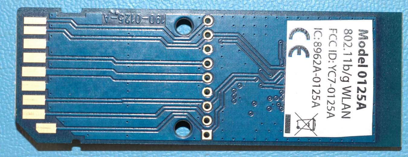
Clarity Design 0125A 802.11b/g WLAN Module FCC/IC ID Label and Location The FCC/IC ID label is shown below. The information is attached on the back of the module as shown in the picture below. The size of the information is 20mm wide X 15mm tall. FCC ID: YC7‐0125A IC: 8962A‐0125A
Evaluation of MPE limit at a given distance Equation from page 18 of OET Bulletin 65, Edition 97-01where: S = power density P = power input to the antennaG = power gain of the antenna in the direction of interest relative to an isotropic radiatorR = distance to the center of radiation of the antenna Maximum peak output power --Conducted 20.48 dBm 0.112 (W) Antenna gain(typical): 2.00 (dBi) Maximum antenna gain: 1.58 (numeric) Evaluation distance: 20.00 (cm) Evaluation frequency: 2412.00 (MHz) Limit from table below: 1 (mW/cm^2) Power density at Evaluation frequency: 0.035 (mW/cm^2) EUT complies FCC/LSGAC Local Official’s Guide to RFA LOCAL GOVERNMENT OFFICIAL'S GUIDE TO TRANSMITTING ANTENNA RFEMISSION SAFETY: RULES, PROCEDURES, AND PRACTICAL GUIDANCE 2 4 R PG S π =
Nemko USA, Inc. 11696 Sorrento Valley Rd., Suite F San Diego, CA 92121-1024 Phone (858) 755-5525 Fax (858) 452-1810 FCC Part 15 Subpart C, 15.247 : 05/04/2011 CERTIFICATION TEST REPORT Report Number: 2011 02167485 FCC Project Number: 1024415 Nex Number: 167485 Applicant: C LARITY DESIGN 13029 D ANIELSON STREET SUITE 100 Poway, CA 92064 Equipment Under Test (EUT): WIFI SD CARD Model: 0125A FCC ID: YC7-0125A IC: 8962A-0125A In Accordance With: FCC Part 15 Subpart C, 15.247 IC RSS-210 Issue 8 December 2010 IC RSS-Gen Issue 3 December 2010 Tested By: Nemko USA Inc. 11696 Sorrento Valley Road, Suite F San Diego, CA 92121 Authorized By: Alan Laudani, EMC/RF Test Engineer Date: A PRIL 5, 2011 Total Number of Pages: 42 Nemko USA, Inc. 11696 Sorrento Valley Road, Suite F, San Diego, CA 92121 Phone (858) 755-5525 Fax (858) 452-1810 FCC ID: YC7-0125A Report Number: 2011 02167485 FCC IC: 8962A-0125A Specification: FCC Part 15 Subpart C, 15.247 Page 2 of 42 Section1: Summary of Test Results All measurements are traceable to national standards. These tests were conducted on a sample of the equipment for the purpose of demonstrating compliance with FCC Part 15; Subpart C and IC RSS-210. Radiated tests were conducted is accordance with ANSI C63.4-2003. Radiated emissions are made on an open area test site. A description of the test facility is on file with the FCC and IC. The assessment summary is as follows: Apparatus Assessed: WiFi SD Card Model: 0125A Specification: FCC Part 15 Subpart C, 15.247 IC RSS-210 Issue 8 December 2010 Date Received in Laboratory: February 23, 2011 Compliance Status: Complies Exclusions: None Non-compliances: None Nemko USA, Inc. 11696 Sorrento Valley Road, Suite F, San Diego, CA 92121 Phone (858) 755-5525 Fax (858) 452-1810 FCC ID: YC7-0125A Report Number: 2011 02167485 FCC IC: 8962A-0125A Specification: FCC Part 15 Subpart C, 15.247 Page 3 of 42 1.1 Report Release History REVISION DATE COMMENTS - April 5, 2011 Prepared By: Alan Laudani - April 5, 2011 Initial Release: Alan Laudani Note that the results contained in this report relate only to the items tested and were obtained in the period between the date of initial receipt of samples and the date of issue of the report. This test report has been completed in accordance with the requirements of ISO/IEC 17025. Nemko USA Inc. authorizes the applicant to reproduce this report provided it is reproduced in its entirety and for use by the company’s employees only. Any use which a third party makes of this report, or any reliance on or decisions to be made based on it, are the responsibility of such third parties. Nemko USA Inc. accepts no responsibility for damages, if any, suffered by any third party as a result of decisions made or actions based on this report. TESTED BY: _ Date: April 5, 2011 Alan Laudani, EMC Test Engineer Nemko USA, Inc. 11696 Sorrento Valley Road, Suite F, San Diego, CA 92121 Phone (858) 755-5525 Fax (858) 452-1810 FCC ID: YC7-0125A Report Number: 2011 02167485 FCC IC: 8962A-0125A Specification: FCC Part 15 Subpart C, 15.247 Page 4 of 42 TABLE OF CONTENTS Section1: Summary of Test Results ............................................................................ 2 1.1 Report Release History ........................................................................................ 3 Section 2: Equipment Under Test ................................................................................ 5 2.1 Product Identification ............................................................................................ 5 2.2 Samples Submitted for Assessment ..................................................................... 5 2.3 Theory of Operation.............................................................................................. 6 2.4 Technical Specifications of the EUT ..................................................................... 6 Section 3: Test Conditions ........................................................................................... 7 3.1 Specifications ....................................................................................................... 7 3.2 Deviations From Laboratory Test Procedures...................................................... 7 3.3 Test Environment ................................................................................................. 7 3.4 Test Equipment .................................................................................................... 8 Section 4: Observations ............................................................................................... 9 4.1 Modifications Performed During Assessment....................................................... 9 4.2 Record Of Technical Judgements ........................................................................ 9 4.3 EUT Parameters Affecting Compliance ................................................................ 9 4.4 Test Deleted ......................................................................................................... 9 4.5 Additional Observations........................................................................................ 9 Section 5: Results Summary ...................................................................................... 10 5.1 Test Results........................................................................................................ 10 Appendix A: Test Results........................................................................................... 11 Section 15.207(a) – Power Line Conducted Emissions................................................. 11 Section 15.215(c) – 20 dB / 99% Bandwidth ................................................................. 19 Section 15.247(a)(2) – Minimum 6dB RF Bandwidth .................................................... 23 Section 15.247(b)(1) – Peak Output Power................................................................... 26 Section 15.247(d) – Band-edge C…
Text truncated - open the document above for the full version.
Module extended from test fixture Conducted emissions Radiated Emissions Analyzer for Conducted Spurious Emissions
13029 Danielson St., Suite 100 · Poway · United States
| # | Rule Parts | Frequency Range | Power Output |
|---|---|---|---|
| 1 | 15C | 2.41 GHz - 2.46 GHz | 111.70 mW |

802.11b/g SDIO Module
Equipment Class
DTS - Digital Transmission System
