YC8-YRG1100-00You Rock Guitar
Inspired Instruments Inc.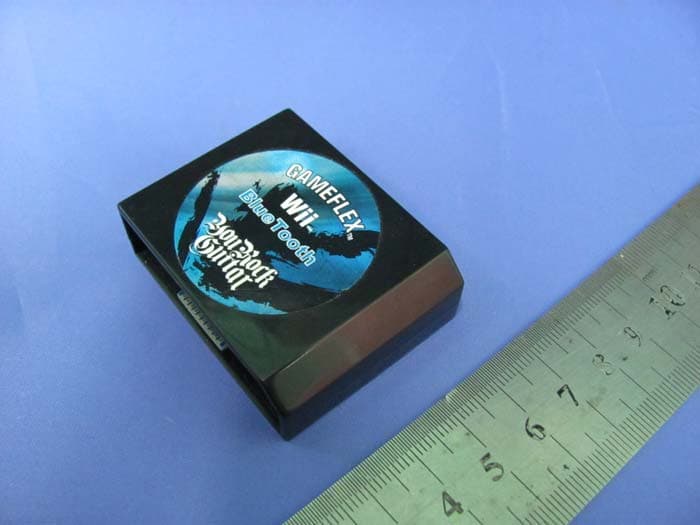
Click to zoom
Application Details
- Equipment Class
- DXX - Part 15 Low Power Communication Device Transmitter
- Date of Grant
- Jul 22, 2010
- Application Purpose
- Original Equipment
- Date of Application
- Jul 22, 2010
- Equipment Note
- You Rock Guitar
- Frequency Range
- 2402.00000000 - 2480.00000000
- Company
- Inspired Instruments Inc.
- Country
- United States
Documents & Files
Document Text
Text extracted from the exhibit documents filed with the FCC. Open a document above to read the original.
Users Manual
ENGLISH PS3™ - Before you can play Playstation 3 games with the You Rock Guitar®, you have to Make sure the Gameflex™ wireless cartridge is paired with your USB dongle. In most cases it is shipped this way. To see if your guitar is paired with the Gameflex™ 1. Insert the You Rock Wireless Gameflex™ cartridge into the You Rock Guitar®. 2. Connect the You Rock Wireless USB dongle to the console’s USB port. 3. Press GAME on the You Rock Guitar®. If the LED displays “2” (not blinking), your Gameflex™ cartridge is already ‘paired’ to the USB dongle. If the LED display blinks “2,” the guitar is not yet ‘paired’. To pair to the USB dongle in your console: 1. Press the button on the Gameflex™ cartridge in your guitar. 2. Press the button on the Gameflex™ Wireless USB dongle (connected to your PS3 game console). The dongle LED blinks rapidly. When it stops blinking, the “2” on your Guitar will also stop blinking and your You Rock Guitar® is ready to play with your Playstation 3 console. Wii™ Before you can play Wii games with the You Rock Guitar®, you have to “sync” it with your console. To sync to the Wii: Insert the Wii BlueTooth Gameflex™ cartridge in your You Rock Guitar®. Open the front panel on your Wii game console, and press the red Sync button. On the control panel, press the GAME button. The display blinks a #1 when not in sync. The #1 will be solid when in sync. If the You Rock Guitar® does not sync, press the RECORD button. The LED display blinks for a moment, and then reads a solid “1” to indicate that the sync was successful. Once the You Rock Guitar® has synced to your Wii, the Wii will recognize it every time you use it. If there is a problem syncing please repeat the process or reboot the guitar. Our You Tube Channel also has a video on syncing to the Wii. FRANCAIS PS3™ - Avant de pouvoir utiliser les jeux Playstation 3 avec la guitare You Rock Guitar®, vérifiez que la cartouche Gameflex™ soit appairée au dongle USB. Dans la plupart des cas, le dongle est fourni directement appairé. Pour vérifier si la guitare est appairée avec la cartouche Gameflex™ : 1. Insérez la cartouche sans fil Gameflex™ dans la You Rock Guitar®. 2. Connectez le dongle sans fil USB au port USB de la console. 3. Appuyez sur la touche GAME de la guitare You Rock®. Si l’écran LED affiche “2” (et ne clignote pas), la cartouche Gameflex™ est déjà appairée au dongle USB. Si l’écran affiche “2” et clignote, la guitare n’est pas encore appairée. Pour appairer la guitare au dongle USB de la console : 1. Appuyez sur la touche de la cartouche Gameflex™ de la guitare. 2. Appuyez sur la touche du dongle USB de communication sans fil Gameflex™ (connecté à la console de jeu PS3). La led du dongle clignote rapidement. Lorsqu’elle cesse de clignoter, le numéro “2” sur la guitare cesse également de clignoter et vous pouvez utiliser la guitare You Rock Guitar® avec votre console Playstation 3. Wii™ - Avant de jouer aux jeux de la Wii avec la guitare You Rock Guitar®, vous devez la “synchroniser” à votre console. Pour synchroniser la guitare à la Wii : Insérez la cartouche Gameflex™ BlueTooth Wii dans la guitare You Rock Guitar®. Ouvrez le compartiment avant de la console de jeu Wii, et appuyez sur la touche rouge Sync. Sur la guitare, appuyez sur la touche GAME. L’écran affiche le numéro 1 en clignotant, lorsque La guitare n’est pas synchronisée. Le numéro 1 reste allumé lorsque la guitare est synchronisée. Si La guitare You Rock® n’est pas synchronisée, appuyez sur la touche RECORD. L’écran Led clignote pendant un instant, puis affiche le numéro “1” qui ne clignote plus et indique que la synchronisation est achevée. Une fois que vous avez synchronisé la You Rock Guitar® avec la Wii, la Wii la reconnaît à chaque utilisation. En cas de problème de synchronisation, répétez le processus ou rebootez la guitare. Notre chaîne vidéo sur You Tube vous montre le film d’installation avec la Wii. ESPAÑOL PS3™ - Antes de que pueda controlar sus juegos Playstation 3 con la You Rock Guitar®, deberá asegurarse de que el cartucho inalámbrico Gameflex™ esté emparejado a su mochila USB. Habitualmente ya vienen de fábrica así. Para comprobar que su guitarra esté emparejada con el Gameflex™ 1. Introduzca en la You Rock Guitar® el cartucho You Rock Wireless Gameflex™. 2. Conecte la mochila USB You Rock Wireless al puerto USB de su consola. 3. Pulse GAME en la You Rock Guitar®. Si en la pantalla LED aparece “2” (fijo, sin parpadear), eso indicará que el cartucho Gameflex™ ya está ‘emparejado’ con la mochila USB. Si en la pantalla LED aparece “2” parpadeando, eso querrá decir que la guitarra todavía no está correctamente ‘emparejada’. Para emparejarlo a la mochila USB de su consola: 1. Pulse el botón del cartucho Gameflex™ de su guitarra. 2. Pulse el botón de la mochila USB del Gameflex™ Wireless (conectado a su consola PS3). El piloto de la mochila parpadeará rápidamente. Cuando deje de hacerlo, la indicación “2” de su guitarra también dejará de parpadear y su You Rock Guitar® ya estará lista para que la pueda usar con su consola Playstation 3. Wii™ - Antes de que pueda controlar sus juegos Wii con la You Rock Guitar®, deberá “sincronizarla” con su consola.Para sincronizarla con la Wii: Introduzca en su You Rock Guitar® el cartucho Wii BlueTooth Gameflex™ . Abra el panel frontal de su consola Wii y pulse el botón rojo Sync. En el panel de control pulse el botón GAME. En la pantalla aparecerá un #1 parpadeando si la guitarra no está sincronizada, mientras que dicho #1 quedará iluminado fijo si la sincronización es correcta. Si la You Rock Guitar® no se sincroniza, pulse el botón RECORD. La indicación de la pantalla LED parpadeará durante un momento y después aparecerá un “1” fijo para indicar que la sincronización ha sido correcta. Una vez que la You Rock Guitar® esté sincronizada con la Wii, la consola la reconocerá cada vez que la use. Si se produce algún problema durante la sincronización, repita todo el proceso o reinicie la guitarra. También …
Text truncated - open the document above for the full version.
Block Diagram
BT Cartridge Block: BT Module Block: RF1 BT79S315 BT Module U1 BT13M880 8MHz SPI interface to Guitar Bluetooth Data Crystal 12MHz BT79P313 Functional Block: 2.4GHz Radio RF Block:
Cover Letter(s)
INSPIRED Instruments Inc Letter of Agency I, an officer of Inspired Instruments, Inc do hereby authorize Intertek Testing Services (Mr. Ben Ho) to act on our behalf in front of the Federal Communications Commission with respect to all matters relating to certification of equipment under Part 15 and Part 18 of the FCC Rules until further notice. I further certify that no party (as defined in §1.2002(b) of CFR 47, 2004) to this application, including myself, is subject to a denial of federal benefits, that includes FCC benefits, pursuant to Section 5301 of the Anti-Drug Abuse Act of 1988, 21 U.S.C.,862. Dated this 29 th day of April 2010 Cliff Elion President, Inspired Instruments, Inc.
External Photos
INTERTEK TESTING SERVICE Report No.: HK10031504-1 FCC ID: YC8-YRG1100-00 IC: 9018A-YRG110000 Equipment Photographs Model : YRG1100 (External)
ID Label/Location Info
Label Location Label size of FCC statement: 45mm X 12mm Label size of FCC ID & IC: 25mm X 5mm
Internal Photos
INTERTEK TESTING SERVICE Report No.: HK10031504-1 FCC ID: YC8-YRG1100-00 IC: 9018A-YRG110000 Equipment Photographs Model : YRG1100 (Internal) INTERTEK TESTING SERVICE Report No.: HK10031504-1 FCC ID: YC8-YRG1100-00 IC: 9018A-YRG110000 Equipment Photographs Model : YRG1100 (Internal) INTERTEK TESTING SERVICE Report No.: HK10031504-1 FCC ID: YC8-YRG1100-00 IC: 9018A-YRG110000 Equipment Photographs Model : YRG1100 (Internal)
Operational Description
Technical Description: The equipment under test (EUTs) is a 2.4GHz GFSK transceiver with using bluetooth techelogy which is designed for a plug in radio device intends to be used with host of “You Rock Guitar”. This wireless cartridge operates at frequency range of 2402MHz to 2480MHz with 79 channels. The EUT is powered by four AA size battery of the “You Rock Guitar”. When the Bluetooth cartridge was installed to Guitar, then Guitar will be connected with Will Game console via the Bluetooth protocol of Bluetooth cartridge act as game controller. Operating Frequency Band: 2402 MHz ~ 2480 MHz Sensitive: down to -81dBm Spread Spectrum: FHSS Modulation Method: GFSK. The functions of main ICs are mentioned as below. 1) RF1 is a Bluetooth module, including the BT79P313 and EEPROM. BT79P313 acts as Bluetooth Chip performs Bluetooth function, EEPROM acts as external memory. 2) U1 acts as MCU for system. BT79P313 This specification are subject to be changed without notice. 3/29/2010 V1.0 - 1 - © 2009 being tech electronic corp. All rights reserved. No parts of this work may be reproduced in any form or by any means - graphic, electronic, or mechanical, including photocopying, recording, taping, or information storage and retrieval systems - without the written permission of the publisher. Products that are referred to in this document may be either trademarks and/or registered trademarks of the respective owners. The publisher and the author make no claim to these trademarks. While every precaution has been taken in the preparation of this document, the publisher and the author assume no responsibility for errors or omissions, or for damages resulting from the use of information contained in this document or from the use of programs and source code that may accompany it. In no event shall the publisher and the author be liable for any loss of profit or any other commercial damage caused or alleged to have been caused directly or indirectly by this document. Printed: December 2009 in Taiwan BT79P313 Specification BT79P313 This specification are subject to be changed without notice. 3/29/2010 V1.0 - 2 - General Description The BT79P313 is a highly integrated single chip Bluetooth device with a stand-alone baseband processor and integrated 2.4 GHz transceiver and is compliant to Bluetooth 2.0. This chip is specifically designed for applications in wireless input devices including keyboards, mice, presenters and gaming controllers. Built-in firmware is fully compliant to Bluetooth ® Human Interface Device (HID) profile. Application − Wireless mouse − Wireless keyboard − Game controllers − Presenters − Remote controls − GPS mouse (G-mouse) RF-Transceiver − Clean, fast hopping synthesizer − 0 dBm, 1 Mbps GFSK transmitter − Analog and Digital filtered receiver − Internal VCO resonator and PLL filter − 50 ohm ant. port eliminates most external RF parts Features − Compliant with Bluetooth ® Specification V2.0 − Compliant with Bluetooth ® HID profile version 1.0 − Support AFH − Embedded 8-bits ’C51 compatible Micro-Controller − Internal 128 kB mask ROM and 8 kB SRAM − On chip support for common mouse sensor interface eliminates external processor − On chip support for Serial Peripheral Interface (SPI) (mater/slave mode) − Optional I 2 C compatible interface − Built-in Power On Reset (POR) − Built-in 8-bit accuracy/10-bit resolution ADC with 4 input channels for detecting low power of battery and reading various analog sensors such as 3-axis accelerometer, etc. − Low Power 1.8V core operation − Integrated Switch-mode Regulators (1 BUCK and 1 BOOST) to support external sensor, LED/Laser and MCU to reduce external BOM cost. − Crystal oscillator with built-in digital trimming − Power management includes digital shutdown and wake up commands with an integrated low power oscillator for sniff mode − Support MCP option with 4 Megabit Flash − Support COB (Chip on Board) option − 56-Pin QFN package available (8 x 8 x 0.9 mm) Antenna MCU ROM RAM UART 12MHz 2.4Ghz Radio Buck SPI XTAL Baseband Figure 1 – Functional Block Diagram Boost 8 bit ADC POR GPIO Batter BT79P313 This specification are subject to be changed without notice. 3/29/2010 V1.0 - 3 - 1. Scope The document is a specification of BT79P313. 1.1 Document Information Document No.: Version: 1.04 Total Page: 28 Date 2009/02/17 Title: ASIC Data Sheet Product Name: BT79P313 1.2 Update History VersioDate/namDescription 0.0 2008/01/24 Established -- -- (status= Preliminary) 1.0 2008/12/03 Change status from Preliminary to Product. Minor updates throughou Indicate Buck regulator output as 1.83V, not 1.8V, wherever applicable. Add Key Features page. Add vendor list for xtal. Add Buck converter output filter values. 1.01 2009/02/02 Fix spelling on all page headers. Page 25: change Rr t Effective 1.02 2009/02/09 P. 1, 13, 18: Update accuracy of ADC to 8-bit. P. 3: Update T.O.C. P. 6: RF Interface: Add pin 57 to table. Clarify pins that are Test Pts. P. 10: Redraw module schematic to eliminate multiple net names. Last page: Remove leading ‘0’ from phone number. 1.03 2009/02/10 P. 5: Fix formatting of Fig. 2. Show pin 57. P. 9: Remove multiple net names on schematic. Correct spelling. P. 10: Additional schematic clean-up. Annotate photo. 1.04 2009/02/17 P. 10: Add/clarify annotations to photo. P. 16: Update Fig. 3 Bluetooth Software Stack. P. 19: Clarify first paragraph; add “optional” for Boost reg. BT79P313 This specification are subject to be changed without notice. 3/29/2010 V1.0 - 4 - Key Features mCommon TX/RX terminal simplifies external matching. mFull RF reference designs available mBluetooth v2.0 Specification compliant Auxiliary Features mCrystal oscillator with built-in digital trimming mPower management includes digital shutdown and wake up commands with an integrated low power oscillator for sniff mode m8-bit ADC available with 4 input channels to applications mBuilt-in power reset to secure IC stability while powering up and to re-start up IC while system…
Text truncated - open the document above for the full version.
Schematics
1 2 34 ABCD 4 3 2 1 D CBA Title Number Revision Size A4 Date: 28-Oct-2009 Sheet of File: E:\ 舊電腦備份 \Di sk -D\Schemati c_20 09\Wi i\Wi i_BT w ireles s_Gu it ar\Wi i_BT w ireles s G uit ar_SGW01 -2_ x Drawn By: Wii_BT wireless_Guitar_SGW01-3.Sch RF Module D1Blue R1 680 CVDD SPI_CSSDOSDI SCLK C222nF C1104 CVDD CVDD LED0 PD3 1 PD4 2 PA2 3 VCC 4 GND 5 PA3 6 PB6 7 PB7 8 PD5 9 PD6 10 PD7 11 PB0 12 PB1 13 PB2 14 PB3 15 PB4 16 PB5 17 AVCC 18 PA0 19 PC7 20 GND 21 PA1 22 PC0 23 PC1 24 PC2 25 PC3 26 PC4 27 PC5 28 PC6 29 PD0 30 PD1 31 PD2 32 U1 BT13M880( QFN32L ) T5 T6T2 PC6 MOSIMISOSPI_CKCART_CSRESETCART_Busy ANT GPIO0TxdRxdLED0 RSTnSCLKSDOSDISPI_CS 1V8 CVDD C422uF (10mil) T14 T8 T3T1T4T7T13 T12T9T10 BT79S316 (Dice) LED1 10 GND 1 GPIO0 2 GPIO1 3 GPIO2 4 LED2 5 LED3 6 Txd_8051 7 Rxd_8051 8 LED0 9 Gnd 27 RSTn 26 HW_SELn 25 SDI 24 SDO 23 SCLK 22 GPIO7 21 Motor_ctrl 20 GPIO5 19 Power-on/off 18 Gnd 17 1V8-Out 16 Batn 11 Batp 12 VDDIO_In 13 Bst_Out 15 1V8_In 14 ANT 29 Gnd 28 Gnd 30 RF1BT79S315 /0805 C522uF /0805 CVDDCVDD SPI_CK RESET Key_SYNC SW1 (open) CVDD T11 (open)(open) C322uF /0805 CVDD MOSI MISO CART_CSCART_Busy 123456789 10 J1SPI Interface T15 T16 GPIO5 首崴電子股份有限公司 BEING TECH ELECTRONICS CORP. 6F.-1, No.371, Sec. 1, Guangfu Rd., Hsinchu City, Taiwan 30074 TEL: 886-3-6660126 FAX: 886-3-6660106 Version: 1.0 - 6 - 九、Schematic BT Module Circuit: 1 2 3 4 5 6 78 ABCD 8 7 6 5 4 3 2 1 D CBA Titl e Number Revision Size A3 Date: 28-Oct-2009 Sheet of File: D:\B project\Wii\sch\090723 BT module\BT module.ddb Drawn By: Wii_BT module_BT79S315.Sch VDD-R 1 ANT 2 VDDI 3 TP 4 TN 5 AVDDA 6 VSS-ADC 7 ADC-IN0 8 VDD-ADC 9 L-K ey/ADC-IN1 10 M-Key/ADC-IN2 11 P-Key/ADC- IN3 12 Z1 13 Z2 14 SCL 15 SDA 16 VSS-IO1 17 VDD-IO1 18 TXD/6 -Key / SPI-SCLK 19 RXD/7 -Key/ SPI-SDO 20 LED0 -OD 21 VDD18 -C1 22 LED1 -OD 23 VSS18-C1 24 Boost-BATN 25 Boost-LX 26 Boost-FB 27 Boost-BATP 28 REG-on/off 29 Buck-FB 30 Buck-BATP 31 Buck-LX 32 Buck-BATN 33 4-Key/SPI-SDI 34 5-Key/SPI-SELn 35 SHTDWN/8B- Key 36 Motion/Wkup 37 SDIO/SDA/MOSI 38 SCLK/SCL 39 VSS-I O2 41 VDD-IO2 40 MI SO 42 NCS/8 A-Key 43 R-Key 44 TM1 45 VDD18 -C2 46 VSS18-C2 47 TM0 48 RST 49 XO 50 XI 51 VDDPL 52 DVDDA 53 VDDC 54 REGO 55 VT 56 VSS- R 57 U1 BT79P313 A0 1 A1 2 A2 3 GND 4 SDA 5 SCL 6 WP 7 VCC 8 U224LC64EEPROM R22K VDD_IO SCLSDA Battery Detector VDD_IO VBAT_ P ADC_IN0 R3 560K/1% R4 560K/1% C8104 SCLBoost_FBBoost_LXSDATXD_K6RXD_K7LED0_ODLED1_OD NCS_8 AKRSTnXOXIREG_Ou t Pow er _On Buck_FB Buck_LX 4_K ey 5_K ey SHTDWN_8BK SDIO_MO SI SCLK_SCL MI SO ANT ADC_IN0 L_Key M_Key P_K ey Z1 Z2 E1 ANTENNA IN 4 OUT 2 GND 1 GND 3 FL1 BF2520-B2R4CAC C11NC C12NC C10 0R CP1 1uF CP21uF VCC_1V8 AVDDA AVDDA VCC_1 V8 1V8_In Boost_BATN Buck_BATN Boost_BATNBuck_BATN VBAT_ P Boost_BATPBuck_BATP VBAT_ P Boost_BATP Buck_BATP VBAT_ P C4 4.7uF R50R VDD_IO1 VDD_IO2 VDD_IO1VDD_IO2 VDD_IO VDD_I O VSS_ IO1VSS18_C1 CP12 1uF CP111uF P12 VSS_I O2 VBAT_ N VSS_ADC VSS18_C2 P13 CP34.7uF VCC_1 V8 VDDPL CP41uF DVDDAVDDC CP54.7uF VDDR CP6 4.7uF VCC_1 V8 VDD18 _ C1 CP81uF VCC_1 V8 VDD18 _ C2 VCC_1V8 CP91uF Y112M XOXI R11M C5 15P C6 15P CLOCK P3 P4 P5 P6 P7 P8P9P10P11 P14P16 L1 SDN2624-100M Buck_FBBuck_LX C14.7uF Buck_Out P17 Internal Boost & Buck VBAT_ P Boost_BATP L2 SDN2624-4R7K Boost_FB C34.7uF Boost_OutBoost_LX P15 C24.7uF C3 will be closed to L2 Power of NetsVBAT_ N P1 P18 P19 P20 P21 P22 P24 P25 P26 P27 P29 P30 VSS_ F VCC_1 V8 CP10 1uF VDD_ADC (open) (open) (open) (Package) (open)
Test Report
INTERTEK TESTING SERVICES Report No.:HK10031504-1 Sample No.:1/1 Code: FCC15C_d / Effective Date: 26 Jan 2010 ( of ) Bandedge Plot – Pursuant to FCC Part 15 Section 15. 249 Requirement
Test Report
- The test report only allows to be revised within the retention period unless further standard or the requirement was noticed. - This report is for the exclusive use of Intertek's Client and is provided pursuant to the agreement between Intertek and its Client. Intertek's responsibility and liability are limited to the terms and conditions of the agreement. Intertek assumes no liability to any party, other than to the Client in accordance with the agreement, for any loss, expense or damage occasioned by the use of this report. Only the Client is authorized to permit copying or distribution of this report and then only in its entirety. Any use of the Intertek name or one of its marks for the sale or advertisement of the tested material, product or service must first be approved in writing by Intertek. The observations and test results in this report are relevant only to the sample tested. This report by itself does not imply that the material, product, or service is or has ever been under an Intertek certification program. Intertek Testing Services Hong Kong Ltd. 2/F., Garment Centre, 576 Castle Peak Road, Kowloon, Hong Kong. Tel: (852) 2173 8888 Fax: (852) 2785 5487 Website: www.hk.intertek-etlsemko.com TEST REPORT Report No.: HK10031504-1 Inspired Instruments, Inc. Application For Certification (Original Grant) (FCC ID: YC8-YRG1100-00) (IC: 9018A-YRG110000) Transceiver Prepared and Checked by: Approved by: Signed On File Kenneth Wong Engineer Chan Chi Hung, Terry Senior Lead Engineer Date: July 21, 2010 INTERTEK TESTING SERVICES Report No.: HK10031504-1 FCC ID: YC8-YRG1100-00 IC: 9018A-YRG110000 i GENERAL INFORMATION Inspired Instruments, Inc. BRAND NAME: Inspired, MODEL: YRG1100 FCC ID: YC8-YRG1100-00 IC: 9018A-YRG110000 Grantee: Inspired Instruments, Inc. Grantee Address: 9800 Irvine Center Drive, Irvine, CA 92618, USA. Contact Person: Cliff Elion Tel: 818-825-0385 Fax: (949) 733-9331 e-mail: [email protected] Manufacturer: Wealthwise Industrial Limited Manufacturer Address: Unit B5-B6, 1/F, Block B, Chung Mei Centre, 15 Hing Yip Street, Kwun Tong, Kowloon, Hong Hong Brand Name: Inspired Model: YRG1100 Type of EUT: Transceiver Description of EUT: You Rock Guitar Serial Number: N/A FCC ID / IC: YC8-YRG1100-00 / 9018A-YRG110000 Date of Sample Submitted: March 31, 2010 Date of Test: April 30, 2010 Report No.: HK10031504-1 Report Date: July 21, 2010 Environmental Conidtions: Temperature: +10 to 40°C Humidity: 10 to 90% INTERTEK TESTING SERVICES Report No.: HK10031504-1 FCC ID: YC8-YRG1100-00 IC: 9018A-YRG110000 ii SUMMARY OF TEST RESULT Inspired Instruments, Inc. BRAND NAME: Inspired, MODEL: YRG1100 FCC ID: YC8-YRG1100-00 IC: 9018A-YRG110000 TEST SPECIFICATION REFERENCE RESULTS Maximum Peak Output Power 15.247(b), (c) / RSS-210 A8.4 N/A Hopping Channel Carrier Frequencies Separation 15.247(e) / RSS-210 A8.1 N/A 20dB Bandwidth of the Hopping Channel 15.247(a) / RSS-210 A8.1 N/A Number of Hopping Frequencies 15.247(e) / RSS-210 A8.1 N/A Average Time of Occupancy of Hopping Frequency 15.247(e) / RSS-210 A8.1 N/A Antenna Conducted Spurious Emissions 15.247(d) / RSS-210 A8.5 N/A Radiated Spurious Emissions 15.247(d) / RSS-210 A8.5 N/A RF Exposure Compliance 15.247(i) / RSS-Gen 5.5 N/A Transmitter Power Line Conducted Emissions 15.207 / RSS-Gen 7.2.2 N/A Transmitter Field Strength 15.227 / RSS-310 3.8 N/A Transmitter Field Strength 15.229 / RSS-210 A2.7 N/A Transmitter Field Strength, Bandwidth and Timing Requirement 15.231(a) / RSS-210 A1.1.1 N/A Transmitter Field Strength, Bandwidth and Timing Requirement 15.231(e) / RSS-210 A1.1.5 N/A Transmitter Field Strength and Bandwidth Requirement 15.239 / RSS-210 A2.8 N/A Transmitter Field Strength and Bandwidth Requirement 15.249 / RSS-210 A2.9 Pass Transmitter Field Strength and Bandwidth Requirement 15.235 / RSS-310 3.9 N/A Receiver Radiated Emissions RSS-210 2.6 Pass Digital Device Conducted Emissions 15.107 / ICES-003 N/A Note: 1. The EUT uses a permanently attached antenna which, in accordance to section 15.203, is considered sufficient to comply with the pervisions of this section. 2. Pursuant to FCC part 15 Section 15.215(c), the 20 dB bandwidth of the emission was contained within the frequency band designated (mentioned as above) which the EUT operated. The effects, if any, from frequency sweeping, frequency hopping, other modulation techniques and frequency stability over excepted variations in temperature and supply voltage were considered. INTERTEK TESTING SERVICES Report No.: HK10031504-1 FCC ID: YC8-YRG1100-00 IC: 9018A-YRG110000 iii Table of Contents 1.0 General Description.......................................................................................... 1 1.1 Product Description ............................................................................................. 1 1.2 Related Submittal(s) Grants ................................................................................ 1 1.3 Test Methodology................................................................................................ 1 1.4 Test Facility ......................................................................................................... 1 2.0 System Test Configuration ............................................................................... 2 2.1 Justification ......................................................................................................... 2 2.2 EUT Exercising Software .................................................................................... 2 2.3 Special Accessories ............................................................................................ 2 2.4 Equipment Modification ....................................................................................... 2 2.5 Measurement Uncertainty ................................................................................... 2 2.6 Support Equipment List and Description ............................................................. 2 3.0 …
Text truncated - open the document above for the full version.
Test Setup Photos
INTERTEK TESTING SERVICE Report No: HK10031504-1 FCC ID: YC8-YRG1100-00 IC: 9018A-YRG110000 Configuration Photographs Worst-Case Radiated Emissions (Front View) Model: YRG1100 INTERTEK TESTING SERVICE Report No: HK10031504-1 FCC ID: YC8-YRG1100-00 IC: 9018A-YRG110000 Configuration Photographs Worst-Case Radiated Emissions (Back View) Model : YRG1100
Contact Information
Applicant
Cliff Elion(President)
Technical Contact
Intertek Testing Services Hong Kong LtdBen Ho
[email protected]852-21738505
2/F Garment Centre · Kowloon · Hong Kong
Non-Technical Contact
Intertek Testing Services Hong Kong LtdBen Ho
[email protected]852-21738505
Test Firm
Intertek Testing Services Hong Kong Ltd.Billy Chow
Technical Specifications
| # | Rule Parts | Frequency Range | Power Output |
|---|---|---|---|
| 1 | 15C | 2.40 GHz - 2.48 GHz | - |
Other Applications from Inspired Instruments Inc.
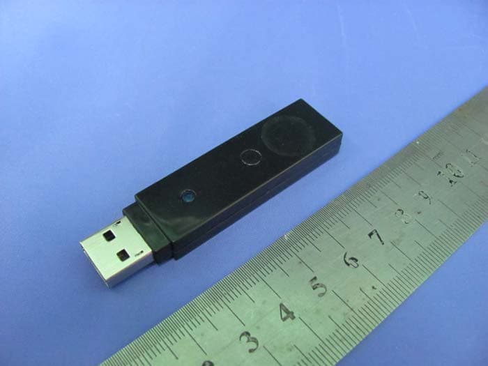
YC8-YRG1103-00
Jul 26, 2010You Rock Guitar
Equipment Class
DXX - Part 15 Low Power Communication Device Transmitter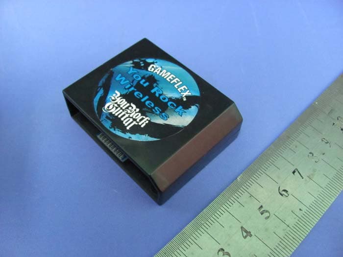
YC8-YRG1101-00
Jul 24, 2010You Rock Guitar
Equipment Class
DXX - Part 15 Low Power Communication Device Transmitter