YCB-ZBA987RFID Module
HACH LANGE GmbH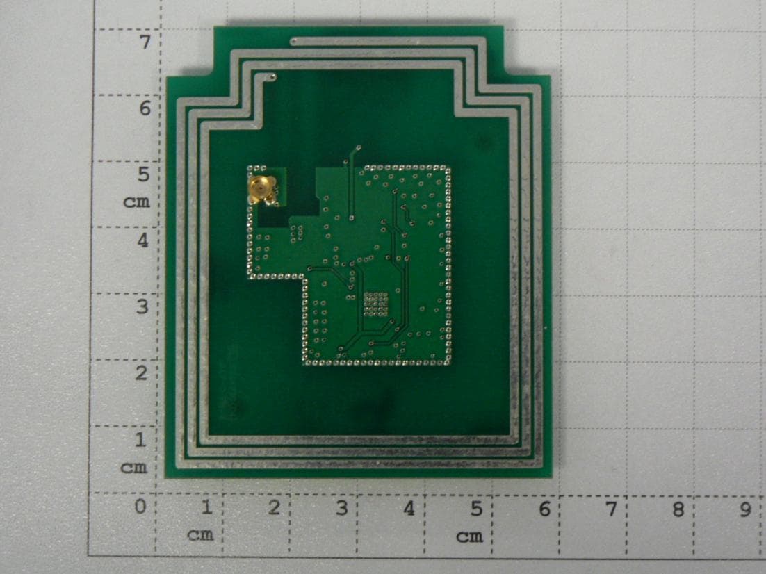
Click to zoom
Application Details
- Equipment Class
- DXX - Part 15 Low Power Communication Device Transmitter
- Date of Grant
- Oct 30, 2012
- Application Purpose
- Original Equipment
- Date of Application
- Oct 30, 2012
- Equipment Note
- RFID Module
- Frequency Range
- 13.56000000 - 13.56000000
- Company
- HACH LANGE GmbH
- Country
- Germany
Documents & Files
Document Text
Text extracted from the exhibit documents filed with the FCC. Open a document above to read the original.
Users Manual
Instruction manual RFID module ZBA987 09/2012 Edition feck/1.1 SIP 10 Service instructions xx/2011 Edition 0.0 This page intentionally left blank. Content 1 GENERAL ............................................................................................................ 5 1.1 Product description ................................................................................................................................... 5 1.2 Specifications ............................................................................................................................................. 5 1.3 Compliance ................................................................................................................................................ 5 2 HW INTEGRATION .............................................................................................. 6 2.1 Connector P101 ......................................................................................................................................... 6 2.2 EMC filtering ............................................................................................................................................. 6 2.3 FCC/IC Compliance.................................................................................................................................. 6 3 PHOTOS .............................................................................................................. 8 This page intentionally left blank. General - 5 - 1 General 1.1 Product description The RFID Module ZBA987 is an easy to use RFID module which can be integrated into HACH LANGE electronics without big effort. This allows us to equip a HACH LANGE product with RFID functionality without designing extra RF board. Thanks to the tested and extremely flexible firmware we can read and write data to any tag that follows the ISO 15693 standard in no time. The rfid module is equipped with a internal PCB antenna. 1.2 Specifications Supply voltage 5 V DC Dimensions 57 x 67 mm RFID protocol ISO 15693 Transmit frequency 13.56 MHz Operating temperature 0...50 °C Storage temperature -40...60°C Communication Interface SPI Bus 1.3 FCC/IC Compliance NOTE: This equipment has been tested and found to comply with the limits for a Class A digital device, pursuant to Part 15 of the FCC Rules. These limits are designed to provide reasonable protection against harmful interference when the equipment is operated in a commercial environment. This equipment generates, uses, and can radiate radio frequency energy and, if not installed and used in accordance with the instruction manual, may cause harmful interference to radio communications. Operation of this equipment in a residential area is likely to cause harmful interference in which case the user will be required to correct the interference at his own expense. NOTICE: This device complies with Part 15 of the FCC Rules [and with RSS-210 of Industry Canada]. Operation is subject to the following two conditions: (1) this device may not cause harmful interference, and (2) this device must accept any interference received, including interference that may cause undesired operation. Changes or modifications made to this equipment not expressly approved by HACH LANGE GmbH may void the FCC authorization to operate this equipment. . - 6 - HW Integration 2 HW Integration 2.1 Connector P101 Pin Function 1, 5, 9 GND 11,12 5 V DC 2,3,4,,6,7,8 SPI Bus 2.2 EMC filtering The RFID Module contains an RF generator at 13.56 Mhz which generates harmonics. These will be radiated from the module below all official limits. When integrating the module into host device with long cables or big ground planes, this effect might increase. It might be advisable to add additional EMC filtering to comply with all relevant norms. 2.3 FCC/IC Compliance for host device The use of the transceiver module is authorized in mobile or fixed host devices taking into account the conditions listed below: OEM Integrator must ensure that the end user manual may not contain any information about the way to install or remove the module from the final product. Depending on the final host device additional authorization requirements for the non- transmitter functions of the transmitter module may be required (i.e., Verification, or Declaration of Conformity) The OEM integrator is responsible for ensuring that after the module is installed and operational the host continues to be compliant with the Part 15B unintentional radiator requirements. The information on the label and in the user manual is required to be incorporated in the user manual of the final host. see 47 CFR15 requirements for more details (e.g. 15.19 / 15.21 / 15.101 / 15.105 / RSS-GEN / ICES) Additional label with the words ‘Contains FCC ID: YCB-ZBA987’ and ‘Contains IC:5879A- ZBA987’ shall be applied and visible from the outside of the host product. The module must be installed and used in strict accordance with the manufacturer’s instructions as described in the user documentation that comes with the module. The end user manual for the final host product operating with this transmitter must include operating instructions to satisfy RF exposure compliance requirements. Radiofrequency radiation exposure Information: This equipment complies with FCC radiation exposure limits set forth for an uncontrolled environment. This equipment should be installed and operated with minimum distance of 20 cm between the radiator and your body. This transmitter must not be co-located or operating in conjunction with any other antenna or transmitter. HW Integration - 7 - The antenna of the module may not be removed, replaced nor modified. The antenna must not be co-located or operating in conjunction with any other antenna or transmitter. No additional antenna must be used. When the final host product operating with this transmitter deviate from above, installation of this module into specific final hosts may require the s…
Text truncated - open the document above for the full version.
External Photos
Page 1 of 4 The test results relate only to the individual items which have been tested. This report shall not be reproduced in parts without the written approval of the testing laboratory © Copyright: All rights reserved by CETECOM Laboratory Accreditation and Listings Reg. No.: 736496 MRA US-EU 0003 Industry Canada Reg. No.: 3462D-1 Reg. No.: 3462D-2 Reg. No.: 3462D-3 Voluntary Controls for Electromagnetic Emissions Reg. No.: R-2665, R-2666 C-2914, T-1967, G-301 accredited according to DIN EN ISO/IEC 17025 CETECOM GmbH Laboratory Radio Communications & Electromagnetic Compatibility Im Teelbruch 116 • 45219 Essen • Germany Registered in Essen, Germany, Reg. No.: HRB Essen 8984 Tel.: + 49 (0) 20 54 / 95 19-954 • Fax: + 49 (0) 20 54 / 95 19-964 E-mail: [email protected] • Internet: www.cetecom.com Annex 2: Internal EUT photographs to TEST REPORT No.: 6-0217-12-2-1a-C1 for RFID Radio Module ZBA987 FCC-ID: YCB-ZBA987 IC: 5879A-ZBA987 According to: FCC Regulations Part 15, Subpart C: §15.225 IC-Regulations RSS-Gen, Issue 3 RSS-210, Issue 8 HACH LANGE GmbH Annex 2 to Test Report 6-0217-12-2-1a-C1, Page 2 of 4 TR6-0217-12-2-1a-A2-C1 Table of contents 1. INTERNAL EUT PHOTOGRAPHS 3 Annex 2 to Test Report 6-0217-12-2-1a-C1, Page 3 of 4 TR6-0217-12-2-1a-A2-C1 1. Internal EUT photographs Photograph 1: EUT (Module) connected to AE1 Photograph 2: EUT - PCB rear side Annex 2 to Test Report 6-0217-12-2-1a-C1, Page 4 of 4 TR6-0217-12-2-1a-A2-C1 Photograph 3: EUT – PCB front side Photograph 4: EUT rear side prepared for conducted tests (RF-connector)
ID Label/Location Info
Label location HACH LANGE ZBA987 RFID Module 13.56 MHz FCC ID: YCB-ZBA987 IC: 5879A-ZBA987 HACH LANGE GmbH Germany v1.0 / eckelmann
Internal Photos
Page 1 of 4 The test results relate only to the individual items which have been tested. This report shall not be reproduced in parts without the written approval of the testing laboratory © Copyright: All rights reserved by CETECOM Laboratory Accreditation and Listings Reg. No.: 736496 MRA US-EU 0003 Industry Canada Reg. No.: 3462D-1 Reg. No.: 3462D-2 Reg. No.: 3462D-3 Voluntary Controls for Electromagnetic Emissions Reg. No.: R-2665, R-2666 C-2914, T-1967, G-301 accredited according to DIN EN ISO/IEC 17025 CETECOM GmbH Laboratory Radio Communications & Electromagnetic Compatibility Im Teelbruch 116 • 45219 Essen • Germany Registered in Essen, Germany, Reg. No.: HRB Essen 8984 Tel.: + 49 (0) 20 54 / 95 19-954 • Fax: + 49 (0) 20 54 / 95 19-964 E-mail: [email protected] • Internet: www.cetecom.com Annex 2: Internal EUT photographs to TEST REPORT No.: 6-0217-12-2-1a-C1 for RFID Radio Module ZBA987 FCC-ID: YCB-ZBA987 IC: 5879A-ZBA987 According to: FCC Regulations Part 15, Subpart C: §15.225 IC-Regulations RSS-Gen, Issue 3 RSS-210, Issue 8 HACH LANGE GmbH Annex 2 to Test Report 6-0217-12-2-1a-C1, Page 2 of 4 TR6-0217-12-2-1a-A2-C1 Table of contents 1. INTERNAL EUT PHOTOGRAPHS 3 Annex 2 to Test Report 6-0217-12-2-1a-C1, Page 3 of 4 TR6-0217-12-2-1a-A2-C1 1. Internal EUT photographs Photograph 1: EUT (Module) connected to AE1 Photograph 2: EUT - PCB rear side Annex 2 to Test Report 6-0217-12-2-1a-C1, Page 4 of 4 TR6-0217-12-2-1a-A2-C1 Photograph 3: EUT – PCB front side Photograph 4: EUT rear side prepared for conducted tests (RF-connector)
Internal Photos
2012 Tag Name External/internal photos . FCC ID: YCB-ZBA987 / IC: 5879A-ZBA987 check. -- feck : file: PN : sheet: 1 ZBA987 01 -- . Ver. Tag Name External/internal photos RFID-module ZBA987 Bottom side top side
Test Report
Zur optimalen Anzeige dieses PDF-Portfolios sollte es in Acrobat oder Adobe Reader ab Version 9 geöffnet werden. Adobe Reader jetzt herunterladen
Test Report
Page 1 of 26 The test results relate only to the individual items which have been tested. This report shall not be reproduced in parts without the written approval of the testing laboratory © Copyright: All rights reserved by CETECOM Laboratory Accreditation and Listings Reg. No.: 736496 MRA US-EU 0003 Industry Canada Reg. No.: 3462D-1 Reg. No.: 3462D-2 Reg. No.: 3462D-3 Voluntary Controls for Electromagnetic Emissions Reg. No.: R-2665, R-2666 C-2914, T-1967, G-301 accredited according to DIN EN ISO/IEC 17025 CETECOM GmbH Laboratory Radio Communications & Electromagnetic Compatibility Im Teelbruch 116 • 45219 Essen • Germany Registered in Essen, Germany, Reg. No.: HRB Essen 8984 Tel.: + 49 (0) 20 54 / 95 19-954 • Fax: + 49 (0) 20 54 / 95 19-964 E-mail: [email protected] • Internet: www.cetecom.com TEST REPORT No.: 6-0217-12-2-1a-C1 for RFID Radio Module ZBA987 FCC-ID: YCB-ZBA987 IC: 5879A-ZBA987 According to: FCC Regulations Part 15, Subpart C: §15.225 IC-Regulations RSS-Gen, Issue 3 RSS-210, Issue 8 HACH LANGE GmbH Test Report 6-0217-12-2-1a-C1, Page 2 of 26 TR6-0217-12-2-1a-C1 Table of contents 1. SUMMARY OF TEST RESULTS...................................................................................................................... 3 1.1. Test overview .................................................................................................................................................. 3 2. ADMINISTRATIVE DATA ............................................................................................................................... 5 2.1. Identification of the testing laboratory ............................................................................................................. 5 2.2. Test location .................................................................................................................................................... 5 2.3. Organizational items ........................................................................................................................................ 5 2.4. Applicant’s details ........................................................................................................................................... 5 2.5. Manufacturer’s details ..................................................................................................................................... 5 3. EQUIPMENT UNDER TEST (EUT) ................................................................................................................. 6 3.1. Technical data of main EUT declared by applicant ......................................................................................... 6 3.2. EUT: Type, S/N etc. and short descriptions used in this test report ................................................................ 6 3.3. Auxiliary Equipment (AE): Type, S/N etc. and short descriptions .................................................................. 6 3.4. EUT set-ups ..................................................................................................................................................... 7 3.5. EUT operating modes ...................................................................................................................................... 7 3.6. Configuration of cables used for testing .......................................................................................................... 7 4. DESCRIPTION OF TEST SYSTEM SET-UP’S .............................................................................................. 8 4.1. Test system set-up for AC power-line conducted emission measurements ..................................................... 8 4.2. Test system set-up for radiated magnetic field measurements below 30 MHz ................................................ 9 4.3. Test system set-up for electric field measurement in the range 30 MHz to 1 GHz ......................................... 10 5. MEASUREMENTS ............................................................................................................................................. 11 5.1. General Limit - Conducted emissions on AC-Power lines .............................................................................. 11 5.2. Radiated field strength emission mask at 13.110-14.010MHz ........................................................................ 13 5.3. General Limit - Radiated field strength emissions below 30 MHz .................................................................. 14 5.4. General Limit - Radiated field strength emissions, 30 MHz - 1 GHz .............................................................. 16 5.5. Frequency error (tolerance) ............................................................................................................................. 18 5.6. Measurement uncertainties .............................................................................................................................. 21 6. ABBREVIATIONS USED IN THIS REPORT ................................................................................................. 22 7. ACCREDITATION DETAILS OF CETECOM’S LABORATORIES AND TEST SITES ......................... 22 8. INSTRUMENTS AND ANCILLARY ................................................................................................................ 23 8.1. Used equipment “CTC” ................................................................................................................................... 23 Table of annex Total pages ANNEX 1: EXTERNAL EUT PHOTOGRAPHS 4 ANNEX 2: INTERNAL EUT PHOTOGRAPHS 4 ANNEX 3: TEST SET-UP PHOTOGRAPHS 4 ANNEX 4: MEASUREMENT DIAGRAMS 20 The listed attachments are an integral part of this report. Test Report 6-0217-12-2-1a-C1, Page 3 of 26 TR6-0217-12-2-1a-C1 1. Summary of test results The test results apply exclusively to the test samples as presented in this Report. The CETECOM GmbH does not assume re…
Text truncated - open the document above for the full version.
Test Setup Photos
Page 1 of 4 The test results relate only to the individual items which have been tested. This report shall not be reproduced in parts without the written approval of the testing laboratory © Copyright: All rights reserved by CETECOM Laboratory Accreditation and Listings Reg. No.: 736496 MRA US-EU 0003 Industry Canada Reg. No.: 3462D-1 Reg. No.: 3462D-2 Reg. No.: 3462D-3 Voluntary Controls for Electromagnetic Emissions Reg. No.: R-2665, R-2666 C-2914, T-1967, G-301 accredited according to DIN EN ISO/IEC 17025 CETECOM GmbH Laboratory Radio Communications & Electromagnetic Compatibility Im Teelbruch 116 • 45219 Essen • Germany Registered in Essen, Germany, Reg. No.: HRB Essen 8984 Tel.: + 49 (0) 20 54 / 95 19-954 • Fax: + 49 (0) 20 54 / 95 19-964 E-mail: [email protected] • Internet: www.cetecom.com Annex 3: Test set-up photographs to TEST REPORT No.: 6-0217-12-2-1a-C1 for RFID Radio Module ZBA987 FCC-ID: YCB-ZBA987 IC: 5879A-ZBA987 According to: FCC Regulations Part 15, Subpart C: §15.225 IC-Regulations RSS-Gen, Issue 3 RSS-210, Issue 8 HACH LANGE GmbH Annex 3 to Test Report 6-0217-12-2-1a-C1, Page 2 of 4 TR6-0217-12-2-1a-A3-C1 Table of contents 1. TEST SET UP PHOTOGRAPHS ....................................................................................................................... 3 Annex 3 to Test Report 6-0217-12-2-1a-C1, Page 3 of 4 TR6-0217-12-2-1a-A3-C1 1. Test set up photographs Photograph 1: Conducted measurements test set-up (climatic tests) Photograph 2: Radiated measurements test set-up (overview) Annex 3 to Test Report 6-0217-12-2-1a-C1, Page 4 of 4 TR6-0217-12-2-1a-A3-C1 Photograph 3: Test set-up radiated – close view Photograph 4: Test set-up: Emissions on AC-mains
Contact Information
Applicant
Michael Schuster(Compliance Manager)
Test Firm
cetecom advanced GmbHGerald Schmidt
Technical Specifications
| # | Rule Parts | Frequency Range | Power Output |
|---|---|---|---|
| 1 | 15C | 13.56 MHz - 13.56 MHz | - |
Other Applications from HACH LANGE GmbH
YCB-LOC100
Sep 08, 2011The LOC 100 RFID Tag read/write device can be used to write the operator ID and location ID to a RFID label on a sampling bottle together with the time and date. This information (sample ID) can then be read by an RFID-compatible photometer
Equipment Class
JBP - Part 15 Class B Computing Device Peripheral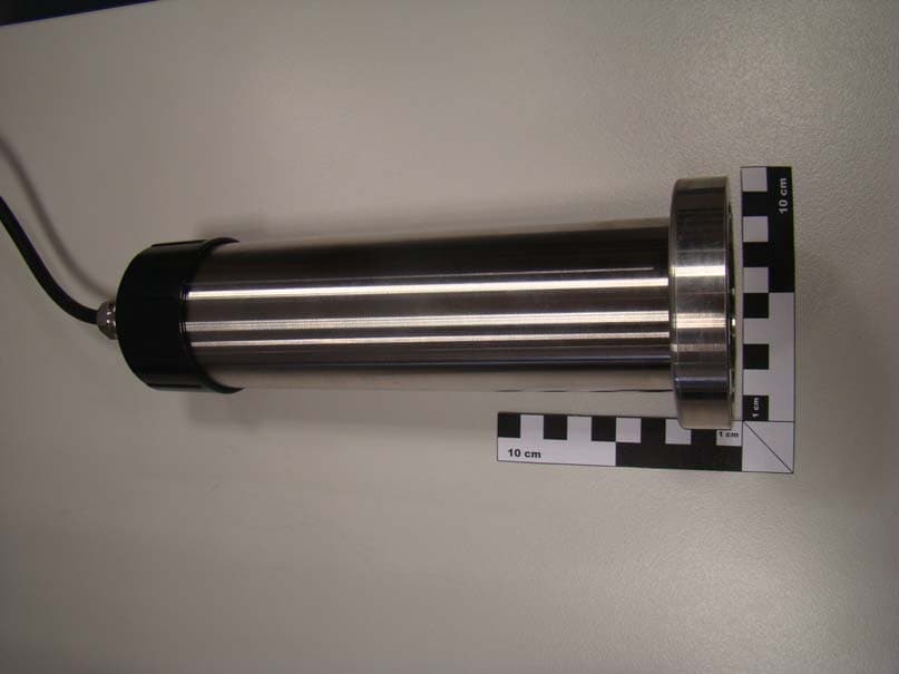
YCB-LXG440
Aug 28, 2011Probe for water analysis with rfid interface
Equipment Class
DXX - Part 15 Low Power Communication Device Transmitter