Text extracted from the exhibit documents filed with the FCC. Open a document above to read the original.
Revision 6/22/10 Confidential – ATEK Products, LLC TankScan TS Series Hardware Installation and User Manual TankScan TS Series Hardware Installation Install the TS Series Controller o Determine the best Controller location Ensure shortest possible distance between all the Monitor locations and the Controller with no obstructions in the path (line of sight). Location should be within a building and near a connection for the mode of communication desired (analog dial up, USB, Ethernet, etc.). o Mount the Controller at the desired location Attach the antenna to the back of the Controller. (Note: the antenna connection is a left-hand thread) Connect power using the wall plug transformer supplied. The LCD panel on the front of the unit should be on after power is applied. Connect the Controller to the desired mode of communication. Install the TS Series Monitor(s) o Determine the desired length of the Monitor probe, cut it to length and attach the supplied weight. o Mount the Monitor onto the tank by threading it onto the 1-1/2” or 2” threaded hole. o Remove the battery compartment door using the supplied screwdriver, insert the battery into the compartment and plug it in. The Monitor will take a measurement and send the information to the Controller within about 10 seconds. Swiping the magnet end of the supplied screwdriver over the “Swipe Magnet Here” label on the Monitor will put the Monitor into “Test” mode. • In “Test” mode the Monitor will continue to take and send measurements approximately every 30 seconds for ten minutes. o Determine and add the “Offset”. The Offset is a function of how and where the monitor is mounted relative to the full level of the tank Manually measure the level in the tank. Calculate the Offset as: Offset = Manual Reading - Monitor Reading Add the calibration Offset to the monitoring software. o Repeat for each Monitor being installed. Refer to the TankScan 2 User Interface Map for viewing data on the LCD panel. Revision 6/22/10 Confidential – ATEK Products, LLC FCC Notes This equipment has been tested and found to comply with the limits for a Class A digital device, pursuant to part 15 of the FCC Rules. These limits are designed to provide reasonable protection against harmful interference when the equipment is operated in a commercial environment. This equipment generates, uses, and can radiate radio frequency energy and, if not installed and used in accordance with the instruction manual, may cause harmful interference to radio communications. Operation of this equipment in a residential area is likely to cause harmful interference in which case the user will be required to correct the interference at his own expense. “This device has been designed to operate with the antenna supplied, and having a maximum gain of 3 dB. Antennas not included or having a gain greater than 3 dB are strictly prohibited for use with this device. The required antenna impedance is 50 ohms.” “To reduce potential radio interference to other users, the antenna type and its gain should be so chosen that the equivalent isotropically radiated power (e.i.r.p.) is not more than that permitted for successful communication.” “To comply with FCC and Industry Canada RF radiation exposure limits for general population, the antennas used for these transmitters must be installed to provide a separation distance of at least 20cm from all persons and they must not be collocated or operated in conjunction with any other antennas or transmitters.” “Changes or modifications not expressly approved by ATEK Products, LLC could void the user’s authority to operate the equipment.”
ATEK Manufacturing, Brainerd, MN 56401-0408 USA Error! Reference source not found. Document Revision: 4.00 Page: 1 of 5 TANKSCAN 2 USER INTERFACE MAP Button Behavior The front panel interface on the ATEK TankScan product consists of a 16x2 character LCD and six pushbuttons. The buttons are mapped as follows: The buttons are intended to behave in a consistent fashion throughout the user interface. The up/down buttons are used to select a particular item in a menu. When editing the value of a field, they are used to increase/decrease the value, or cycle through the available options. The left/right buttons are not used at the main level of the menu system, but are used in the tank status viewer to select a different probe. When editing certain types of fields, the buttons are used to move the cursor left/right. The menu button is used primarily to “go back” one level in the menu, or abort the current operation. The select/enter button is used to select an item to “drill down” in a menu, to select a field for editing, or when editing a field, to commit a change. In one instance, the front panel buttons are used as a password entry field, and the keys take on slightly different meanings. The values 1-5 and enter are shown in the button mapping above. Refer to the user interface map at the end of this document for a quick reference. ATEK Manufacturing, Brainerd, MN 56401-0408 USA Error! Reference source not found. Document Revision: 4.00 Page: 2 of 5 Menu Items 1. Status Display The status display cycles through several useful screens of information on a periodic basis. It is refreshed once per second, and cycles to a new screen every 5 seconds. All status screens display the current time on the top line. The first status screen displays the unit serial number on the second line. 1a. Next Report Time This screen shows the time at which the unit is scheduled to next report. 1b. Last Report Status This screen shows the status of the last report attempt (OK or FAIL), and the time at which it was attempted. 1c. Controller Temperature This screen shows the current temperature of the controller unit. 1d. Reporting Started This screen is shown when the scheduled report time has been reached, or an alarm or other condition has caused reporting. It indicates that the unit is currently attempting to contact the server. 1e. Reporting Active This indicates that an active and successful reporting session is ongoing. 2. System Configuration This option leads to a selection of menu items which will configure a few system-wide options. 2a. Password Entry A simple password field is required to change these settings. By default, the password is 5-4-3-2-1-enter. This is a hardcoded password in the unit firmware. 2b. Billing Day This setting changes the day of the month that is considered the billing day, used for scheduling reporting. 2c. Measure Units This setting configures whether the measurement units are metric or imperial. 2d. Radio Mode This changes the controller radio mode between “old” mode (compatible with old probes only) or “new” mode (compatible with new probes only). 3. IP Configuration This option leads to a selection of menu items which allow configuration of the Ethernet networking interface. These settings are only relevant when the Ethernet uplink mode is selected. 3a. DHCP This setting configures whether the unit will attempt to acquire its IP settings automatically using DHCP, or whether they will be configured statically. Note that a reboot of the controller is required when this change is made. 3b. Static IP Address When in static IP mode, this is where the unit’s IP address is set. 3c. Static Network Mask When in static IP mode, this is where the unit’s network mask is set. 3d. Static Gateway ATEK Manufacturing, Brainerd, MN 56401-0408 USA Error! Reference source not found. Document Revision: 4.00 Page: 3 of 5 When in static IP mode, this is where the unit’s default gateway is set. 3e. Static Primary DNS When in static IP mode, this is where the primary DNS server is set. 3f. Static Secondary DNS When in static IP mode, this is where the secondary DNS server is set. 4. Uplink Configuration This option leads to a selection of menu items which allow configuration of the uplink connection. 4a. Uplink Mode This setting allows choosing between the modem, USB and Ethernet modes of uplink connection. 4b. Minimum Time Between Calls This setting controls the minimum allowable time between calls. This allows throttling the time between calls so that it does not dial in too often. Units are in minutes. 4c. Maximum Time Between Calls This setting controls the maximum allowed time between calls. This ensures the unit reports at least as often as this setting. Units are in minutes. 4d. Repeat Alarm Call Time ?? 4e. Maximum Tries to Call This setting controls the maximum number of attempts that the controller will make at a given reporting time to try to contact the server. 4f. Begin Call Hour This setting controls the start of a window in which the controller is allowed to connect to a server for reporting. 4g. End Call Hour This setting controls the end of a window in which the controller is allowed to connect to a server for reporting. 4h. Power Alarm This setting controls whether the controller will report immediately after restoration of power after an outage. 4i. Dial Phone Number This setting is used to set the primary phone number that will be used for dialing. This is only relevant in “Telephone Line” uplink mode. 4j. Dial Prefix This setting is used to control the prefix needed for dialing out, often “9” or “9W”. This is only relevant in “Telephone Line” uplink mode. 4k. Dial Suffix This setting is used to control any necessary suffix for dialing out. This is only relevant in “Telephone Line” uplink mode. 4l. Dial Mode This setting is used to control whether the modem will dial using tone or pulse dialing when it dials. This is only relevant in “Telephone Line” uplink mode. 5. Tank Status Th…
Text truncated - open the document above for the full version.
Controller FCC Label location: C en t ered n e ar t h e fro n t o n t h e b o t t o m .
EK0419-1 Atek Companies Internal Pictures YCLTSC7 EK0419-1 Atek Companies Internal Pictures YCLTSC7
EK0419-1 Atek Companies Internal Pictures YCLTSC7
Prediction of MPE limit at a given distance Equation from page 18 of OET Bulletin 65, Edition 97-01 where:S = power density P = power input to the antenna G = power gain of the antenna in the direction of interest relative to an isotropic radiator R = distance to the center of radiation of the antenna Maximum peak output power at the antenna terminal: 5.94(dBm) Maximum peak output power at the antenna terminal:3.926449354(mW) Antenna gain(typical):3(dBi) Maximum antenna gain:1.995262315(numeric) Prediction distance:20(cm) Prediction frequency: 915(MHz) MPE limit for uncontrolled exposure at prediction frequency:0.6(mW/cm^2) Power density at prediction frequency:0.001559(mW/cm^2) Therefore device complies with FCC and Industry Canada RF radiation exposure limits for gereral population as a mobile device (distance > 20cm) 2 4R PG S π =
Curtis-Straus LLC is accredited by the American Association for Laboratory Accreditation for the specific scope of accreditation under Certificate Number 1627-01. This report may contain data which is not covered by the A2LA accreditation. ____________________________________________________________ Curtis-Straus LLC, a wholly owned subsidiary of BV CPS One Distribution Center Circle, #1 • •• • Littleton, MA • •• • TEL (978) 486-8880 • •• • FAX (978) 486-8828 page 1 of 27 Test Report Curtis-Straus LLC, a wholly owned subsidiary of BV CPS Report No KE0419-1 Client ATEK Products, LLC Address 210 NE 10 th Ave. Brainerd, MN 56401 Phone 763.392.5897 Items tested Tank Scan II Controller FCC ID YCLTSC7 IC ID 8942A-TSC7 FRN 0017195009 Equipment Type Digital Spread Spectrum Equipment Code DSS Emission Designator FCC/IC Rule Parts 47 CFR 15.247, RSS 210 issue 7 and RSS GEN issue 2 Test Dates April 27-30, 2010 and May 20, 2010 Results As detailed within this report Prepared by Matthew Burman– Test Engineer Authorized by Mairaj Hussain – EMC Supervisor Issue Date May 28, 2010 Conditions of Issue This Test Report is issued subject to the conditions stated in the ‘Conditions of Testing’ section on page 26 of this report. Test Report for ATEK Products, LLC • •• • Report No. EK0419-1 July 12, 2010 ______________________________________________________________________ ____________________________________________________________ Curtis-Straus LLC, a wholly owned subsidiary of BV CPS One Distribution Center Circle, #1 • •• • Littleton, MA • •• • TEL (978) 486-8880 • FAX (978) 486-8828 page 2 of 27 Contents Contents..................................................................................................................................2 Summary.................................................................................................................................3 Test Methodology ....................................................................................................................3 Product Tested - Configuration Documentation .......................................................................4 Test Set-up Diagram ............................................................................................................4 Statement of Conformity......................................................................................................5 Test Results ............................................................................................................................6 Bandwidth............................................................................................................................6 Peak Power.........................................................................................................................8 Band Edge Measurements.................................................................................................10 Frequency Hopping Timing Requirements.........................................................................12 Frequency Hopping Channel Separation...........................................................................14 Radiated Spurious Emissions............................................................................................15 Conducted Spurious Emissions.........................................................................................17 AC Line Conducted Emissions...........................................................................................19 Voltage Variations..............................................................................................................20 Occupied Bandwidth..........................................................................................................21 Measurement Uncertainty......................................................................................................23 Test Equipment Used ............................................................................................................24 Product Documentation .........................................................................................................25 Conditions Of Testing ............................................................................................................26 Form Final Report REV 7-20-07 (DW) Test Report for ATEK Products, LLC • •• • Report No. EK0419-1 July 12, 2010 ______________________________________________________________________ Release Control Record Issue No. Reason for change Date Issued 1 Original Release July 12, 2010 _____________________________________________________________ Curtis-Straus LLC, a wholly owned subsidiary of BV CPS One Distribution Center Circle, #1 • •• • Littleton, MA • •• • TEL (978) 486-8880 • •• • FAX (978) 486-8828 page 3 of 27 Summary This test report supports an application for certification of a transmitter operating pursuant to 47 CFR 15.247 and RSS-210. The product is the Tank Scan II Controller. It is a transmitter that operates in the range 902-928MHz. We found that the product met the above requirements with modification (see details in Comments for Statement of Compliance Section). Brad Cole from ATEK Products, LLC. was present during the testing. The test sample was received in good condition. Test Methodology Radiated emission and AC Line conducted testing was performed according to the procedures specified in ANSI C63.4 (2009) and RSS-GEN. Radiated Emissions were maximized by rotating the device around three orthogonal axes as well as varying the test antenna’s height and polarity. The device antenna cannot be maximized separately. Conducted emission at the antenna port was performed, as required by rule section. Spurious emissions from 30-1000MHz were performed outside of the plastic enclosure, presenting a worst case radiation level. AC mains line conducted emission were performed using a 50Ω/50μH LISN. The EUT operating voltage is 120Vac 60Hz. The following bandwidths were…
Text truncated - open the document above for the full version.
EK0419-1 Atek Companies Test Setup Pictures YCLTSC7 Conductive Measurements EK0419-1 Atek Companies Test Setup Pictures YCLTSC7 Radiated Measuremetns below 1GHz EK0419-1 Atek Companies Test Setup Pictures YCLTSC7 Radiated Measurements Above 1GHz EK0419-1 Atek Companies Test Setup Pictures YCLTSC7 AC mains Line Conducted Measurements - Front EK0419-1 Atek Companies Test Setup Pictures YCLTSC7 AC mains Line Conducted Measurements - Rear
| # | Rule Parts | Frequency Range | Power Output |
|---|---|---|---|
| 1 | 15C | 913 MHz - 926.6 MHz | 4.00 mW |

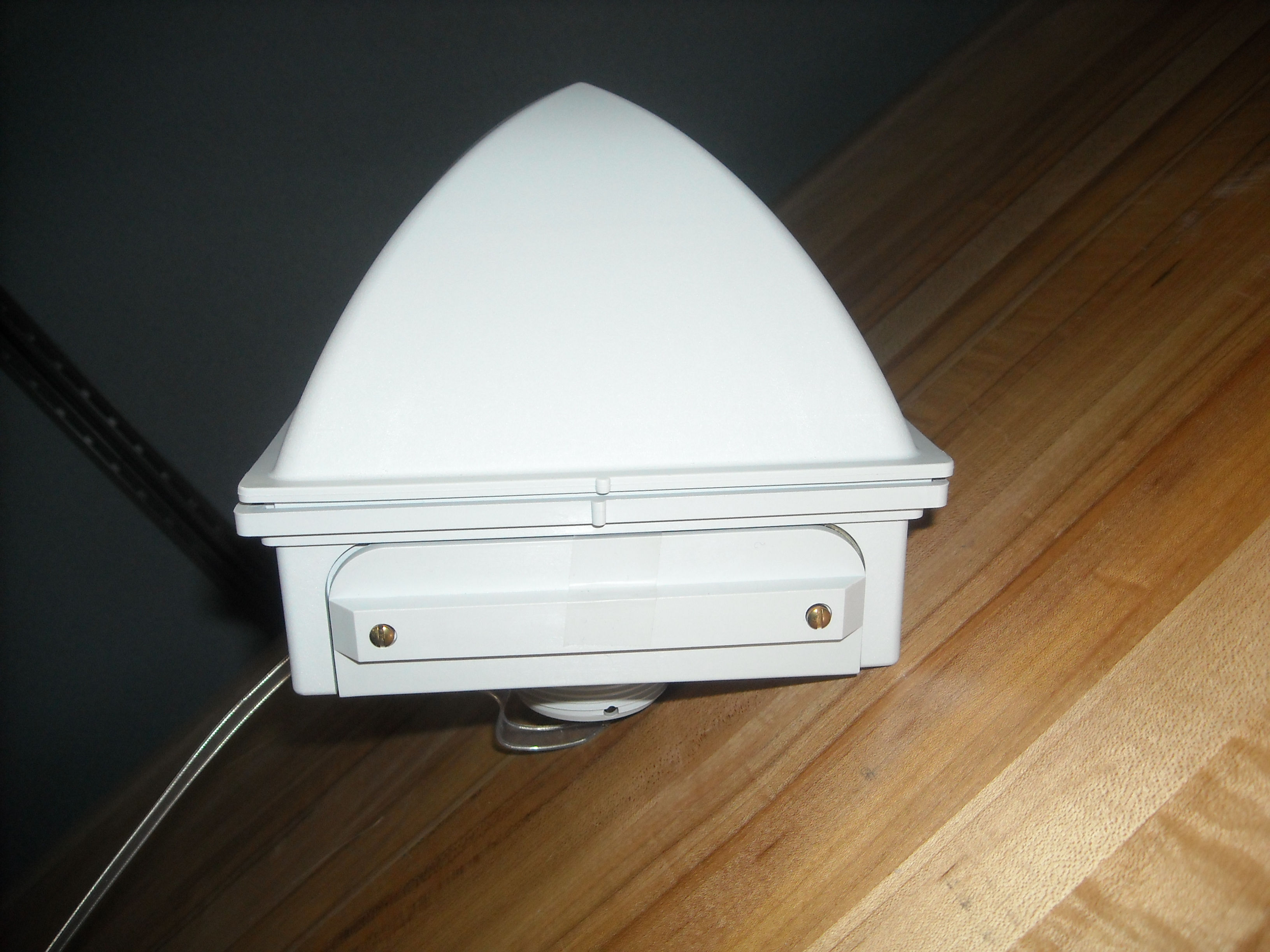
TankScan TS Series Monitor
Equipment Class
DXX - Part 15 Low Power Communication Device Transmitter