YCQ-SPL32RWirelessTourGuideSystem
SOOLAI ELECTRONICS CO., LTD.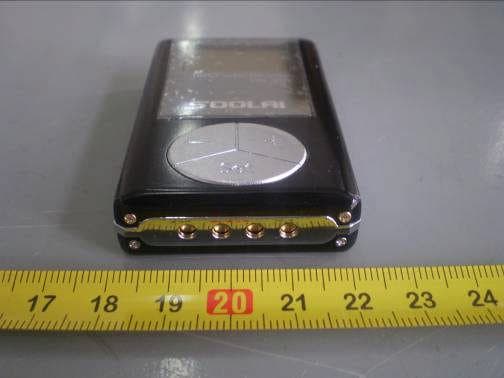
Click to zoom
Application Details
- Equipment Class
- CXX - Communications Rcvr for use w/ licensed Tx and CBs
- Date of Grant
- May 05, 2010
- Application Purpose
- Original Equipment
- Date of Application
- May 05, 2010
- Equipment Note
- WirelessTourGuideSystem
- Frequency Range
- 614.25000000 - 697.62500000
- Company
- SOOLAI ELECTRONICS CO., LTD.
- Country
- China
Documents & Files
Document Text
Text extracted from the exhibit documents filed with the FCC. Open a document above to read the original.
Users Manual
SPL-32R/SPL-32T UHFWireless Tour Guide System User Manual SPL-32TSPL-32R SOOLAIELECTRONICS CO.,LTD -2- Thank you for choosing SOOLAI! Please take a few moments to read these instructions carefully, as we want you to enjoy your new SOOLAI products quickly and to the fullest. Special features ●Super portable design-Super mini, lightweight, metal shell ●UHF professionalfrequency, PLL synthesized design, 32 channels available ●"DigitalPilotone & Noise Lock" dual-squelch Circuitry ●High performance double-IF circuit design ●96*64 dot matrixWhite LCD display ●LCD display Channel, frequency, volume, battery, RF level, AF level, transmitter gain,RF power, and lock.Mode ●Transmitter dynamic display of AF level,AFoverloadwarning, 31-step microphone gain adjustment design ●Quick-mute function ●Receiverdigital16-step volume control ●Receiverdigital21-step SQ adjusting ●Panellockwith password ●Built-in polymer batteryworking for 10hours ●uniqueclip-worn design ●system support ofinputting background musicwhile talking ●Operatingrange300ft(line-of-sight) Main Applications: IndustryTouring Widely used in touring, visiting museums, exhibitions Guest reception Used in reception of visitants in product presentation, advanced exhibition of large companies Teaching Used in meeting and teaching of school and so on Simultaneous interpretation International conference simultaneous interpretation Stage monitoring Monitoringof performance: especiallyforacting singer to monitor accompaniment -3- CONTENT SPL-32R receiver...... ... ... ....... ... ... ... ... ... ... ... ... ... ... ... ... ... ....... 04 Operating controls... ... ... ... ...... ... ... ......... ... ... ... ... ... ... ... ... ... ...05 Adjusting channel/frequency... ... ... ........ .......... ... ... ... ... ... ... ..... 06 Adjusting the squelch threshold... ... ... ............... ... ... ... ... ... ... ... ..... 06 Setting locking/unlocking... ... ... .......... ...... ... ... ...... ... ... ... ... ... .... 07 Exiting from setting operation... ... ... ... ....... ... ... ... ... ... ... ... ... ... ..... 07 SPL-32T transmitter... ... ... ... ... ... ... ........... ... ... ... ... ...... ... ... ..... 08 Operating controls... ... ... ... ... ... ... ... ... .............. ... ... ... ... ....... ....09 Adjusting channel/frequency... ... ... ... ... ... ........... ...... ... ... ... ... .....10 Adjusting microphone gain... ... ... ... ... ... ... ... ......... ........ ... ... ... .....10 Adjusting transmitting power... ... ... ... ... ... ... ... ........ ... ... ... ... ... .....11 Setting locking/unlocking.... ... ... ... ... ... ... ... ... ... ... ......... ... ...... ....11 Operating belt clip... ... ... ... ... ... ... ... ... ... ... ... ... ... ... ........ ... ... .....12 SC-02 two unit charger... ... ... ... ... ... ....................................................... 14 SCB-20 twenty unit charging and storing case...... ... ... ...... ........ ... ..... 15 Application samples... ... ... ... ... ... ... ... ... ... ... ... ... ... ... ... ... ... ... ... ... ... ... ....16 Troubleshooting... ... ... ... ... ... ... ... ... ... ... ... ... ... ... ... ... ... ... ... ... ... ... ... ... ...18 Specifications... ... ... ... ... ... ... ... ... ... ... ...... ... ........ ... ... ....... ... .... 19 FCC STATEMENT.................. ........ ... ......... ... ... ...... ......................20 Warranty... ... ... ... ... ... ... ... ... ... ... ... ... ... ... ... ... ... ... ... ... ... ......... 21 -4- SPL-32R receiver SPL-32RLCD (figure 1) (1).LCD (2).On/Off button (keeping it pressed for 3 seconds will switch the receiver on) (3).Tiepillar or 1/4 wavelengthflexibleantenna (4).3.5 mm jack socket for headphones (5).Rocker button (UP) (6).Rocker button (DOWN) (7).SET button (8).Charging contact (9).Channeldisplay (10).Frequency display (11).16-step headphone output volume display (12).6-step dynamic RF display (13).Lock mode icon (lock mode is activated) (14).4-step battery status display (15).6-step dynamic AF display (16).Audio overloaddisplay,‘OL’means transmitter microphone input volume is too high.It needs to be reduced (adjusting transmitterAF gain until there is no OL on display) -5- Operating controls 1.Via keeping ON/OFF button pressed for 3 seconds, you can switch the receiver on. 2.Via pressing UP or DOWN button, you can add or reduce headphone volume.(The minimum is 1, and the max is 16.) 3.Via keeping ON/OFF button pressed for 3 seconds, you can switch receiver off. 4.Via keeping“”button pressed for 3 seconds, you can enter the operatingmenu, as shown in the figure 2. If there is no operatingmenu, you will see the code inputting picture, as shown in the figure 3. It means the former user has set the lock mode. You have to input the code, if you want toenter. Please refer to (Setting Locking/unlocking ) (figure 2)(figure 3) ●The battery is flat if you can not switch the receiver on. You have to charge before switchit again. ●The receiver willpoweroff automatically to protect the lithium-ion batterywhen the battery is flat. Please charge the battery. ●While the transmitter off, please check the RF onLCDof receiver. If there is no RF volume display, it means no frequency interference. You can use this channel, as shown in the figure 4. If there is RF volume display, it means the frequency is interfered. Pleaseuseanother channel,as shown in the figure5.(Please refer to adjusting channel/frequency)If there is AF volumeon display, it means the receiver has received signal from one transmitter which is swtiched on(as shown in the figure 6). ●Set the volume for the connected headphones tothe minimum before putting the headphones on. figure 4figure 5figure 6 -6- Adjusting channel/frequency 1.Keeping SET button pressed for 3 seconds, you can enter the operatingmenu. 2.Via“”or“”button, you can select“SET CH”icon, as shown in the figure 7. Then press SET button to enter, as shown in the figure 8. 3.Via“”or“”button, you can go to t…
Text truncated - open the document above for the full version.
Cover Letter(s)
SOOLAI ELECTRONICS CO.,LTD _____________________________________________ SCS-F18: Project and Product Certification Representative Authorization LetterPage1of2Rev 2.0 2206 Ringwood Avenue San Jose, CA 95131 Tel: 408-526-1188 Fax: 408-526-1088 Email: [email protected] Project and Product Certification Representative Authorization Letter Revision History Reason for Amendment (current / obsolete) FromTo Approved Date Initial Release (current)1.01.0Nov-14-2006 Revised wording(current)1.02.0Sept–25-2007 SOOLAI ELECTRONICS CO.,LTD _____________________________________________ SCS-F18: Project and Product Certification Representative Authorization LetterPage2of2Rev 2.0 (April 21, 2010) To: SIEMIC, INC. 2206 Ringwood Avenue, San Jose, CA 95131 USA Dear Sir/Madam, Re:Project and ProductCertification Representative Authorization Letter We,SOOLAI ELECTRONICS CO.,LTDhereby authorize SIEMIC, INC. to act as a Certification Bodyforcertifyingfor thefollowing project(s): Product description:Wireless Tour Guide System model name:SPL-32R We affirm that between SIEMIC andSOOLAI ELECTRONICS CO.,LTD, any difference in understanding, including test plan, measurement methods, applicable standards and relevant procedures and processes have been resolved prior to commencement of testing activities. Sincerely, Signature: Name:Ocean Si Title:R & D Manager CompanyName:SOOLAI ELECTRONICS CO.,LTD Address:Xishanqiao,Yuhuatai Zone,Nanjing,China 210041 Telephone:86-25-52803489 Fax No.:86-25-84083635
Cover Letter(s)
SCS-F19: Confidentiality Request Letter Rev 1.0 Nov 14, 2006 Confidentiality Request Letter Reason for Amendment (current / obsolete) Revision History Approved Date From To Initial Release (current) 1.0 1.0 Nov-14-2006 SCS-F19: Confidentiality Request Letter Rev 1.0 Nov 14, 2006 SOOLAI ELECTRONICS CO.,LTD _____________________________________________ (May 7, 2010) To: Federal Communications Commission Authorization and Evaluation Division Confidentiality Request regarding application for certification of FCC ID: YCQ-SPL32R We hereby request confidential treatment of information accompanying this application as outlined below: - Block Diagram - Schematics - Operational Description The above materials contain trade secrets and proprietary information not customarily released to the public. The public disclosure of these materials may be harmful to the applicant and provide unjustified benefits to its competitors. The applicant understands that pursuant to Section 0.457 & 0.459 of the Rules, disclosure of this application and all accompanying documentation will not be made before the date of the Grant for this application. Sincerely, Signature: Name : Ocean Si Title: R & D Manager Company Name: SOOLAI ELECTRONICS CO.,LTD Address: Xishanqiao,Yuhuatai Zone,Nanjing,China 210041 Telephone: 86-25-52803489 Fax No.: 86-25-84083635
External Photos
Front View of EUT Rear View of EUT Top View of EUT Bottom View of EUT Left View of EUT Right View of EUT
ID Label/Location Info
Label Location
ID Label/Location Info
FCC ID:YCQ-SPL32R This device complieswith Part 15 of the FCC Rules.Operation is subject to the following two conditions: (1) This device may not cause harmful interference. (2) This device must accept any interference received, including interference
Test Report
SOOLAIELECTRONICSCO.,LTD WirelessTourGuideSystem Model:SPL-32R 6April,2010 ReportNo.:1002034-E (This report supersedesNONE) Modifications made to the product : None This Test Report is Issued Under the Authority of: PeterCai ComplianceEngineer Jackson Chen Technical Manager This test report may be reproduced in full only. Test result presented in this test report is applicable to the representative sample only. Title:EMCTest Report forWirelessTourGuideSystem Model:SPL-32R To:FCCPart15SubpartBClassB:Jul.2009,ANSIC63.4:2009 Serial#:1002034-E Issue Date:6April,2010 Page:2of39 www.siemic.com Thispage has been left blank intentionally. Title:EMCTest Report forWirelessTourGuideSystem Model:SPL-32R To:FCCPart15SubpartBClassB:Jul.2009,ANSIC63.4:2009 Serial#:1002034-E Issue Date:6April,2010 Page:3of39 www.siemic.com CONTENTS 1EXECUTIVE SUMMARY &EUTINFORMATION.............................................................................................................4 2TECHNICAL DETAILS..................................................................................................................................................5 3MODIFICATION............................................................................................................................................................6 4TEST SUMMARY..........................................................................................................................................................7 5MEASUREMENTS, EXAMINATION ANDDERIVED RESULTS........................................................................................8 ANNEX A. TEST INSTRUMENTATION.................................................................................................................................16 ANNEX B.EUT AND TEST SETUPPHOTOGRAPHS...........................................................................................................20 ANNEX C.TEST SETUP AND SUPPORTING EQUIPMENT...................................................................................................21 ANNEXD.USER MANUAL / BLOCKDIAGRAM / SCHEMATICS/ PART LIST.......................................................................25 ANNEXE.SIEMIC ACCREDITATIONCERTIFICATES..........................................................................................................26 Title:EMCTest Report forWirelessTourGuideSystem Model:SPL-32R To:FCCPart15SubpartBClassB:Jul.2009,ANSIC63.4:2009 Serial#:1002034-E Issue Date:6April,2010 Page:4of39 www.siemic.com 1Executive Summary & EUTInformation The purpose of this test program was to demonstrate compliance of theSOOLAIELECTRONICS CO.,LTDWirelessTourGuideSystem, against the current Stipulated Standards. TheWirelessTour GuideSystemhasdemonstrated compliance with theFCCPart15SubpartBClassB:Jul.2009. EUT Information EUT Description WirelessTourGuideSystem Model No SPL-32R Serial No N/A Input Power 3.6Vdc,50mA Classification Per Stipulated Test Standard ClassBEmissionProduct Note: Only Model SPL-32R was tested, since the electrical circuit design, layout, components used and internal wiring were identical for the following models. Only difference is appearance. Listed models: H-100R, SPL-79R,PR-32 Title:EMCTest Report forWirelessTourGuideSystem Model:SPL-32R To:FCCPart15SubpartBClassB:Jul.2009,ANSIC63.4:2009 Serial#:1002034-E Issue Date:6April,2010 Page:5of39 www.siemic.com 2TECHNICAL DETAILS Purpose Compliance testing ofWirelessTourGuideSystemwith stipulated standards Applicant / Client SOOLAIELECTRONICSCO.,LTD Xishanqiao,YuhuataiZone,Nanjing,China210041 Manufacturer SOOLAIELECTRONICSCO.,LTD Xishanqiao,YuhuataiZone,Nanjing,China210041 Laboratory performing the tests SIEMIC Nanjing(China)Laboratories NO.2-1,Longcang Dadao, Yuhua Economic Development Zone, Nanjing, China Tel:+86(25)86730128/86730129 Fax:+86(25)86730127 Email:[email protected] Test report reference number1002034-E Date EUT receivedMarch19,2010 Standard applied FCCPart15SubpartBClassB:Jul.2009 Dates of test (from–to) April2,2010 No of Units#1 Equipment CategoryReceiver Trade NameSOOLAI Microprocessor (s)Unidentified RF Operating Frequency (ies)614MHz-634MHz, 678MHz-698MHz Clock/Oscillator Frequency (ies) N/A Rated Input Power 3.6Vdc, 50mA Port/ConnectorsN/A FCC ID:YCQ-SPL32R Title:EMCTest Report forWirelessTourGuideSystem Model:SPL-32R To:FCCPart15SubpartBClassB:Jul.2009,ANSIC63.4:2009 Serial#:1002034-E Issue Date:6April,2010 Page:6of39 www.siemic.com 3MODIFICATION NONE Title:EMCTest Report forWirelessTourGuideSystem Model:SPL-32R To:FCCPart15SubpartBClassB:Jul.2009,ANSIC63.4:2009 Serial#:1002034-E Issue Date:6April,2010 Page:7of39 www.siemic.com 4TEST SUMMARY The product was tested in accordance with the following specifications. All Testing has been performed according to below product classification: ClassB Emission Product Test Results Summary Emissions Test StandardDescription Product Class Pass / Fail FCCPart15SubpartBClassB:Jul. 2009 AC Line Conducted Emissions See Above N/A FCCPart15SubpartBClassB:Jul. 2009 Radiated Emissions See Above Pass All measurement uncertainty is not taken into consideration for all presented test result. Title:EMCTest Report forWirelessTourGuideSystem Model:SPL-32R To:FCCPart15SubpartBClassB:Jul.2009,ANSIC63.4:2009 Serial#:1002034-E Issue Date:6April,2010 Page:8of39 www.siemic.com 5MEASUREMENTS, EXAMINATION AND DERIVED RESULTS 5.1AC Line Conducted EmissionsTest Result Note: 1. All possible modes of operation were investigated. Only the 6 worst case emissions measured, using the correct CISPR and Average detectors, are reported. All other emissions were relatively insignificant. 2. A "-ve" margin indicates a PASS as it refers to the margin present below the limit line at the particular frequency. 3. Conducted Emissions Measurement Uncertainty All test measurements carried out are traceable to national standards. The uncertainty of the measurement at a confidence level of approximately 95% (in the case where distributions are n…
Text truncated - open the document above for the full version.
Contact Information
Applicant
Ocean Si(R & D Manager)
Test Firm
SIEMIC (Nanjing-China) LaboratoriesLeslie Bai
Technical Specifications
| # | Rule Parts | Frequency Range | Power Output |
|---|---|---|---|
| 1 | 15B | 614.25 MHz - 697.625 MHz | - |
Other Applications from SOOLAI ELECTRONICS CO., LTD.

YCQ-MC20
Mar 26, 2026Magnetic Wireless Charger
Equipment Class
DCD - Part 15 Low Power Transmitter Below 1705 kHz
YCQ-SPL32T
May 05, 2010WirelessTourGuideSystem
Equipment Class
TBF - Licensed Broadcast Transmitter Held to Face