YE3800DMobile Tablet
DT Research, Inc.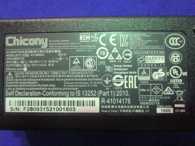
Click to zoom
Application Details
- Equipment Class
- JBC - Part 15 Class B Computing Device/Personal Computer
- Date of Grant
- Jul 14, 2015
- Application Purpose
- Original Equipment
- Date of Application
- Jul 14, 2015
- Equipment Note
- Mobile Tablet
- Company
- DT Research, Inc.
- Country
- Taiwan
Documents & Files
Document Text
Text extracted from the exhibit documents filed with the FCC. Open a document above to read the original.
Users Manual
DT311 BASIC OPERATION GUIDE ENGLISH INTRODUCTION Thank you for acquiring the latest addition to DT Research’s line of tablets — the DT311. Featuring a slim yet robust enclosure, the DT311 with 11.6” TFT display is powered by the Intel® processor, offering optimal combinations of performance and power savings. The DT311 is available with Microsoft® operating systems. Each software operating system features web browser, client/ server computing software, media player, accessories, and applications support. PACKAGE CONTENTS • One DT311 with Battery Pack and Handstrap • Capacitive Touch Stylus and Lanyard • AC‐DC Power Adapter with Power Cord • Basic Operation Guide *The actual package contents may vary depending on the configuration acquired. DT311 DT311: Input/ Output Ports Button Functions A USB 3.0 port BUTTON ACTION B Headphone Jack 1 programmable button C DC Power Input 2 power button D Smart Card Reader 3 Keyboard Wedge E Back Camera ENGLISH 2 Power/Battery LED Status: • Blue indicates the battery is 25% to 100% charged • Blinking blue indicates the battery is charging • Orange indicates that the battery is between 11% to 25% • Blinking Orange indicates that the battery is below 10% Precautions • Always exercise care when operating and handling the DT311. • Do NOT apply excessive pressure to the display screen. • Avoid prolonged exposure of the display panel to any strong heat source. Wherever possible, the DT311 should face away from direct light to reduce glare. • If the AC‐DC power adapter is used to recharge or power the tablet, do NOT use any AC‐DC adapter other than the one provided or acquired from the manufacturer or its partners. • In the unlikely event that smoke, abnormal noise, or strange odor is present, immediately power off the DT313 and disconnect all power sources. Report the problem to your device provider immediately. • Never attempt to disassemble the DT311, as this will void the warranty. THE DT311 Basic Features The DT311 wireless tablet integrates a bright and multi‐touch display, one USB port, and embedded networking elements such as wireless LAN and Bluetooth. The DT311 is complemented by a suite of accessories, including battery expansion, charging cradles, and battery charger kit, for a comprehensive user experience. A DT311 typically integrates an 802.11ac wireless LAN (WLAN) adapter that may connect to other wireless devices or access points. If your DT311 does not come with such a network adapter, please consult your device provider to establish the desired network connectivity ENGLISH 3 DT311 OPERATION Internal Battery Warning! ! The Internal battery pack should only be replaced by an authorized DT Research service representative. Please contact your product and/or service provider for internal battery replacement service. Powering ON and OFF To activate the DT311, push and quickly release the Power Button. The display will come on in a few seconds. To put the DT311 in Standby mode, push and quickly release the Power Button. To turn the DT311 off for extended storage, power off safely using any software function that "shuts down computer" provided in the software operating system. NOTE: The battery packs shipped with your tablet may be low in power—please use the AC‐DC adapter with the DT311 when setting up for the first time to fully charge the internal battery pack. You may charge the external battery pack with it attached to the DT311, or with the optional external battery charger kit. NOTE: When the battery pack(s) is (are) charging, the blue‐colored Battery LED should blink slowly. If plugging in the AC‐DC adapter does not trigger this blinking activity and the LED stays dark, the battery pack(s) may have been drained substantially. Try unplugging/ replugging the AC‐DC adapter to the DT311 a few times to activate the charging process. NOTE: To conserve power, use (push and quick release) the Power Button to put the tablet in “Standby” mode while not in use. Pushing briefly on the same button will wake up the system within seconds. NOTE: Avoid using the Power Button (“hold 4+ seconds” feature) to turn off the tablet—this form of hardware shutdown is intended to be a means of recovery from lockups, and not as normal operation. ENGLISH 4 Start Up If the power up (from Standby or otherwise) is successful, the appropriate interface will be displayed after a launch sequence of several seconds. The wireless LAN connection may take 10‐15 seconds to be established. Configuring the Mobile Tablet The DT311 may be configured using the utilities and methods dictated by the software operating system. The DT311 should be configurable for various properties such as user profiles, network features, and several system elements. Wireless Networking Wireless LAN The DT311 is often delivered with an embedded (user‐inaccessible) 802.11ac WLAN adapter equipped with a hidden custom antenna. • Through the support of typical WLAN adapters, the DT311 should be able to detect all 802.11 access points in the vicinity for you to select the access point of your choice for connection. • The SSID and WEP/WPA/WPA2 (if enabled) parameters on the DT311 and the access points have to match. The SSID is case‐sensitive and it is recommended that you enable WEP/WPA/WPA2 encryption (or advanced alternatives) for secure access. • When WEP/WPA/WPA2 is enabled, you may need to consult your network administrator or your networking equipment literature to properly configure associated settings such as Authentication mode, etc. • Refer to the access point operating manuals for setting up the 802.11 access points. ENGLISH 5 DT311 Bluetooth The Bluetooth configuration application is enabled from the System Tray or from the Windows Mobility Center. Follow the instructions and options provided within the application to configure and invoke Bluetooth connectivity with the corresponding peripherals. USING THE MOBILE TABLET Peripherals Support Through its USB port, the DT311 supports a wide range of USB…
Text truncated - open the document above for the full version.
External Photos
EXHIBIT B - EUT EXTERNAL PHOTOGRAPHS EUT – All View EUT – Adapter View EUT – Adapter Lable View EUT – Top View EUT – Bottom View EUT – Side View EUT – Side View EUT – Side View EUT – Side View EUT – Port View EUT – Port View EUT – Port View
ID Label/Location Info
EXHIBIT A - FCC ID LABELING AND LOCATION FCC ID Label Proposed FCC ID Label Location The label shown shall be permanently affixed at a conspicuous location on the device and be readily visible to the user at the time purchase (Labeling requirements per 2.925)
Internal Photos
EXHIBIT C - EUT INTERNAL PHOTOGRAPHS EUT –Uncover View EUT –Uncover View EUT –UncoverView EUT –UncoverView EUT –Battery Top View EUT –Batery Bottom View EUT –Battery Label View EUT –Battery Top View EUT –Battery Bottom View EUT –LTE&CDMA Antenna 1 View EUT –LTE&CDMA Antenna 2 View EUT –Wifi & BT Antenna 1 View EUT –Wifi & BT Antenna 2 View EUT –Uncover View EUT –Uncover View EUT –Main Board Top 1 View EUT –Main Board Bottom 1 View EUT –Main Board Top 2 View EUT –Main Board Bottom 2 View EUT –Main Board Top 3 View EUT –Main Board Bottom 3 View EUT –Uncover View EUT –Main Board Top 4 View EUT –Main Board Bottom 4 View EUT –Main Board Top 5 View EUT –Main Bottom Top 5 View EUT –Main Board Top 5 Uncover View EUT –Main Board Top 5 Uncover View EUT –Block Top 1 View EUT –Block Bottom 1 View EUT –Block 1 Top Uncover View EUT –Block 1 Chip View EUT –Main Board Bottom 5 Uncover View EUT –Main Board Bottom 5 Uncover View EUT –Block Top 2 View EUT –Block Bottom 2 View EUT –Block 2 Top Uncover View EUT –Block 2 Chip View EUT –Main Board Top 6 View EUT –Main Board Bottom 6 View EUT –Uncover View EUT –Main Board Top 7 View EUT –Main Board Bottom 7 View
Test Report
Note: This test report is prepared for the customer shown above and for the device described herein. It may not be duplicated or used in part without prior written consent from Bay Area Compliance Laboratories Corp. (Dongguan). This report is valid only with a valid digital signature. The digital signature may be available only under the Adobe software above version 7.0. FCC PART 15 B TEST REPORT For DT Research Inc. 6F., NO.1, Ning-Po E. Street, Taipei 100, Taiwan. FCC ID: YE3800D Model: DT311 Report Type: Original Report Product Type: Mobile Tablet Te s t E n g i n e e r : Dean Liu Report Number: RDG150615001-00D Report Date: 2015-07-01 Reviewed By: Sula Huang RF Leader Test Laboratory: Bay Area Compliance Laboratories Corp. (Dongguan) No.69 Pulongcun, Puxinhu Industrial Zone, Tangxia, Dongguan, Guangdong, China Tel: +86-769-86858888 Fax: +86-769-86858891 www.baclcorp.com.cn Bay Area Compliance Laboratories Corp. (Dongguan) Report No.: RDG150615001-00D FCC Part 15 B Page 2 of 18 TABLE OF CONTENTS GENERAL INFORMATION ....................................................................................................................................... 3 PRODUCT DESCRIPTION FOR EQUIPMENT UNDER TEST (EUT) .................................................................................... 3 OBJECTIVE ................................................................................................................................................................... 3 RELATED SUBMITTAL(S)/GRANT(S) ............................................................................................................................. 3 TEST METHODOLOGY .................................................................................................................................................. 3 TEST FACILITY ............................................................................................................................................................. 3 SYSTEM TEST CONFIGURATION .......................................................................................................................... 4 DESCRIPTION OF TEST CONFIGURATION ...................................................................................................................... 4 EUT EXERCISE SOFTWARE .......................................................................................................................................... 4 EQUIPMENT MODIFICATIONS ....................................................................................................................................... 4 LOCAL SUPPORT EQUIPMENT LIST AND DETAILS ........................................................................................................ 4 SUPPORT CABLE LIST AND DETAILS ............................................................................................................................ 4 CONFIGURATION OF TEST SETUP ................................................................................................................................. 5 SUMMARY OF TEST RESULTS ............................................................................................................................... 6 FCC§15.107 - CONDUCTED EMISSIONS ................................................................................................................ 7 MEASUREMENT UNCERTAINTY .................................................................................................................................... 7 EUT SETUP .................................................................................................................................................................. 7 EMI TEST RECEIVER SETUP ......................................................................................................................................... 8 TEST EQUIPMENT LIST AND DETAILS ........................................................................................................................... 8 TEST PROCEDURE ........................................................................................................................................................ 8 CORRECTED AMPLITUDE & MARGIN CALCULATION ................................................................................................... 8 TEST RESULTS SUMMARY ............................................................................................................................................ 9 TEST DATA .................................................................................................................................................................. 9 FCC §15.109 - RADIATED SPURIOUS EMISSIONS ............................................................................................ 12 MEASUREMENT UNCERTAINTY .................................................................................................................................. 12 EUT SETUP ................................................................................................................................................................ 12 EMI TEST RECEIVER SETUP ....................................................................................................................................... 13 TEST PROCEDURE ...................................................................................................................................................... 14 TEST EQUIPMENT LIST AND DETAILS ......................................................................................................................... 14 CORRECTED AMPLITUDE & MARGIN CALCULATION ................................................................................................. 14 TEST RESULTS SUMMARY .......................................................................................................................................... 14 TEST DATA ...................................…
Text truncated - open the document above for the full version.
Test Setup Photos
EXHIBIT D - TEST SETUP PHOTOGRAPHS Conducted Emissions – Front View Conducted Emissions - Side View Radiated Emission - Front View (Below 1GHz) Radiated Emission - Rear View (Below 1GHz) Radiated Emission - Front View (Above 1GHz) Radiated Emission - Rear View (Above 1GHz)
Contact Information
Applicant
JS Hsu
Test Firm
Bay Area Compliance Laboratories Corp. (Dongguan)John Chan
[email protected]86-769-86858888
Technical Specifications
| # | Rule Parts | Frequency Range | Power Output |
|---|---|---|---|
| 1 | 15B | - | - |
Other Applications from DT Research, Inc.

YE3FSC-BT909C
Jun 12, 2023Bluetooth Module
Equipment Class
DTS - Digital Transmission System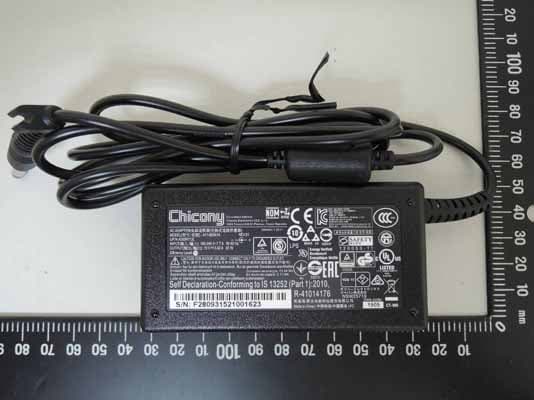
YE3800E
Jul 30, 2015Mobile Tablet
Equipment Class
PCB - PCS Licensed Transmitter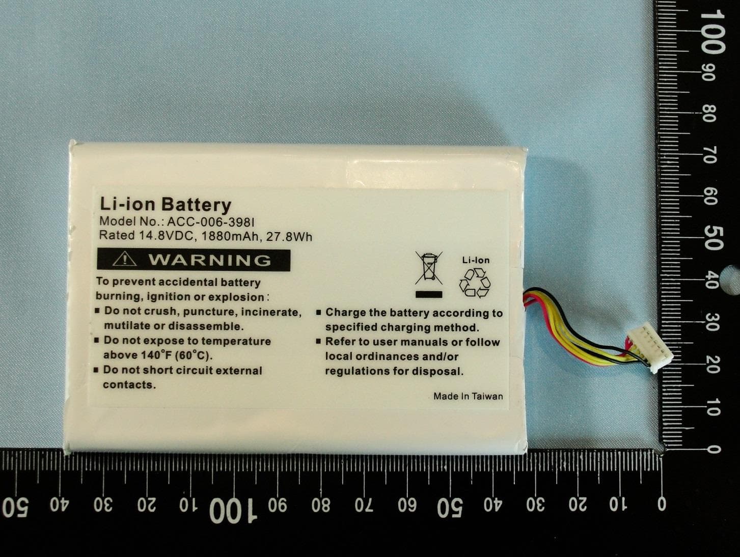
YE3800C
Jan 22, 2015Mobile Tablet
Equipment Class
PCB - PCS Licensed Transmitter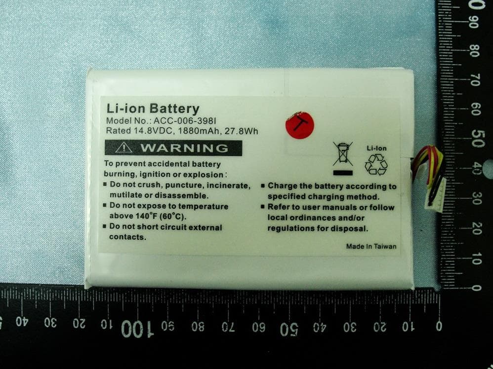
YE3800B
Apr 09, 2013MOBILE TABLET
Equipment Class
PCB - PCS Licensed Transmitter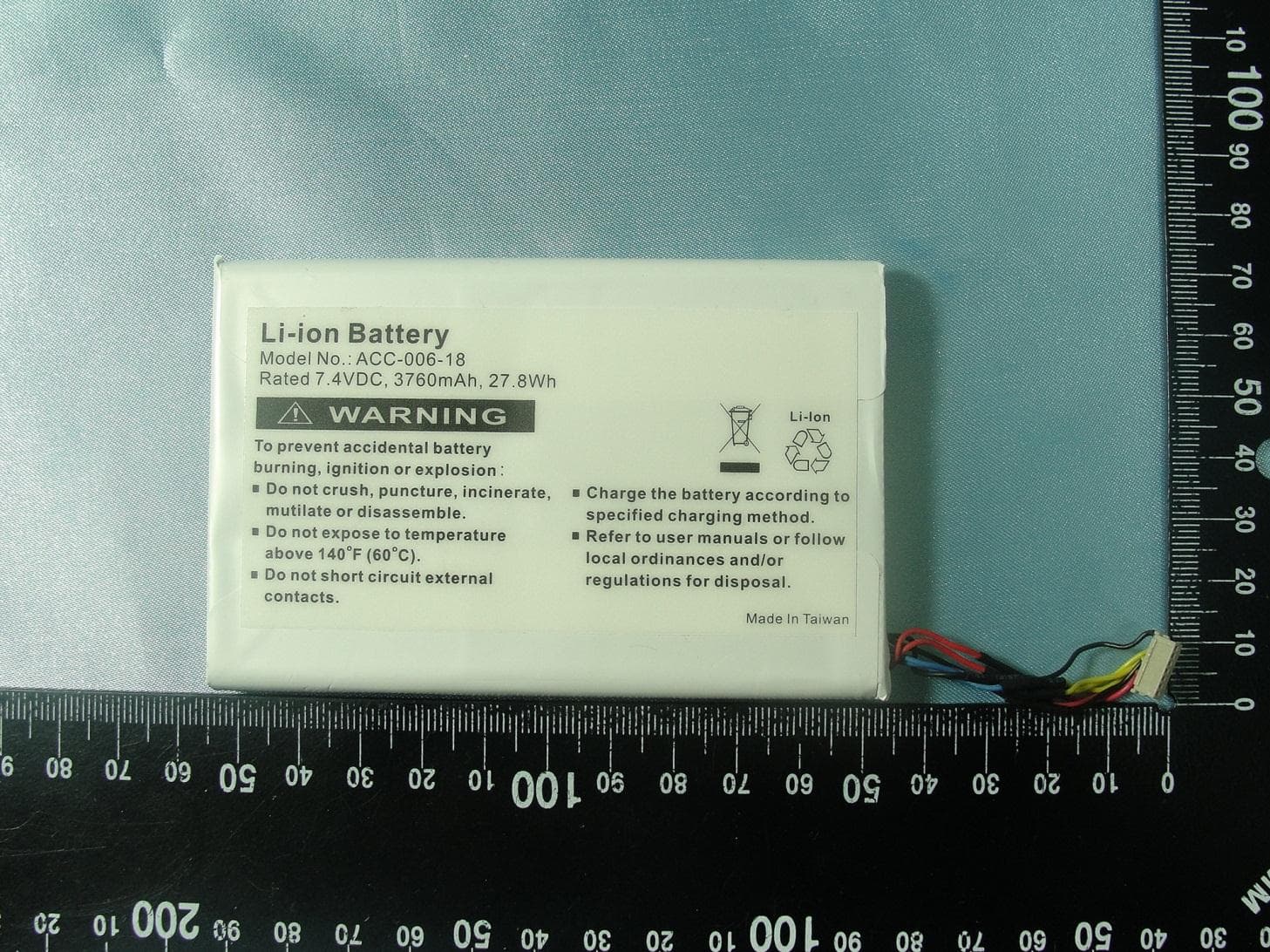
YE3800A
Jan 28, 2013MOBILE POS TABLET
Equipment Class
PCB - PCS Licensed Transmitter