YE4X2SCar Infortainment System Center
Glosys Inc.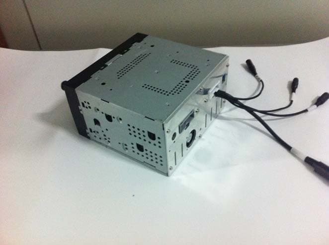
Click to zoom
Application Details
- Equipment Class
- DSS - Part 15 Spread Spectrum Transmitter
- Date of Grant
- Apr 27, 2014
- Application Purpose
- Original Equipment
- Date of Application
- Apr 27, 2014
- Equipment Note
- Car Infortainment System Center
- Frequency Range
- 2402.00000000 - 2480.00000000
- Company
- Glosys Inc.
- Country
- South Korea
Documents & Files
Document Text
Text extracted from the exhibit documents filed with the FCC. Open a document above to read the original.
Users Manual
XiteSolutions North America Inc. 1 XSG2NA-X2S INFOTAINMENT CENTER Owner’s Manual Before using this product, please read this manual fully to ensure correct operation. Keep the manual at hand for future reference. Content.................................................................................2 Disclaimer.......................................................................... 3-5 1. Features............................................................................6 2. Main Unit Display...............................................................7-8 Content XiteSolutions North America Inc. 2 2.1 Main Menu......................................................................9 2.2 Information Bar.................................................................9 3. Set up..........................................................................10-12 3.1 General Settings......... .................................... ............10-11 3.2 Video Settings................................................................12 3.3 Audio Setup...................................................................13 4. Radio Operation..................................................................14 5. USB-MP3/WMA/MP4 Player Operation...................................15 6. CD Player Operation...........................................................16 7. DVD/VCD Player Operation..................................................17 7.1 DVD System Setting.........................................................17 8. Bluetooth Operation... .....................................................18-21 8.1 Bluetooth Setup..............................................................18 8.2 Pairing Your Phone.....................................................19-20 8.3 Incoming Calls...............................................................21 8.4 Outgoing Calls...............................................................21 8.5 AV (A2DP Audio Playback over Bluetooth)...........................22 9. Sirius XM Satellite Radio......... ............................................23-30 9.1 Subscribing to SiriusXM...................................................23 9.2 Operating SiriusXM.........................................................24 9.3 Tuning to a channel.........................................................25 9.4 Parental Control Channel Locking and Skipping....................26 9.4.1 Lock Code................................................................ 26 9.4.2 Lock Mode/Unlock Mode..............................................26 9.4.3 Mature Channel Locking...............................................26 9.4.4 Channel Locki ng.................................... .....................26 9.4.5 Channel Skip.............................................................26 9.5 Artist & Song Alerts.........................................................27 9.5.1 Setting Alerts.............................................................27 9.5.2 Viewing & Managing Alerts...........................................27 9.5.3 My Artists & My Songs Virtual Categories........................27 9.6 Replay..........................................................................28 9.7 SiriusXM Settings Menu...................................................29 9.8 Understanding SiriusXM Advisory Messages........................30 10. iPod & iPhone AV Interface......... ................................ ...........31 11. F-AUX & AUX Operation....................................................32 13. Navigation (Optiona l)................................. ........................33 12. Camera (Optional)............................................................34 14. Premium Remote Control (Optional).................................35-37 15. Customer Feedback..........................................................38 16. Product registration...........................................................39 Notes..................................................................................40 Disclaimer XiteSolutions North America Inc. 3 THIS IS A DISCLAIMER OF LIABILITY AND DAMAGE RESPONSIBILITY AS REGARDS TO THE INFOTAINMENT CENTER MANUFACTURER AND YOUR USE OF THE PRODUCT. YOU ASSUME TOTAL RESPONSIBILITY AND RISK FOR USING THIS SYSTEM. Failure to properly focus on the operation of your motor vehicle can result in death, serious injury and property damage. The I nfotainment Center should never be used at a time or in a manner that distracts you from properly focusing on operation of the motor vehicle in which it is installed. Always operate the vehicle in a safe manner and in full compliance with speed limits, road safety signs and all other laws and devices which regulate operation of a motor vehicle. Always remain aware of driving conditions at all times when using this system while operating a motor vehicle. Operation of this unit, including its camera, navigation, audio and other features can be distracting to your operation of the motor vehicle. While the system is intended to provide both entertainment and helpful vehicle and navigation information, it is not intend ed to, nor should you allow it to, distract you from properly f ocusing on operating the motor vehicle in which it is installed. It is up to you to minimize or prevent such distraction. Learn how to use this system before placing the vehicle in operat ion. Minimize the amount of time spent viewing the screen of t he unit while driving and use voice prompts whenever possible. Do not attempt to adjust settings of the system or resolve any malfunctio n with it while driving. Instead, pull off the road in a safe and legal manner, and then adjust its settings or deal with any malfunction. In the event of serious malfunction, disable the unit (turn power off or remove power from the system) and contact qualified se rvice personnel. Your optional navigation feature is intended to assist you with guidance to your destination. The navig…
Text truncated - open the document above for the full version.
Cover Letter(s)
Glosys Inc. #510, Venture Valley B/D, 40 Omokcheon-Ro 152 Beon-Gil, GwonseonGu, SuwonSi, GyeonggiDo, 441-813, South Korea Tel : +82-31-291-1450, Fax : +82-31-291-1451 http://www.glosys.co.kr/ Federal Communications Commission Authorization and Evaluation Division 1435 Oakland Mills Road Columbia, MD 21046 Date: April, 16, 2014 SUBJECT: FCC Application for (FCCID: YE4X2S) To Whom It May Concern: We, the undersigned, hereby attest to the fact that we will apply the Declaration of Conformity procedure to the class B computer peripheral portion of this composite filing. Regards, Youngjin Choi / Sales Manager Glosys Inc.
Cover Letter(s)
Glosys Inc. #510, Venture Valley B/D, 40 Omokcheon-Ro 152 Beon-Gil, GwonseonGu, SuwonSi, GyeonggiDo, 441-813, South Korea Tel : +82-31-291-1450, Fax : +82-31-291-1451 http://www.glosys.co.kr/ Date: 2014.04.16 Federal Communications Commission 7435 Oakland Mills Road Columbia MD 21046 To whom it may concern: I, the undersigned, hereby authorize Uk Cho Lim of KOREA TESTING & RESEARCH INSTITUTE and hereafter referred to as KOREA TESTING & RESEARCH INSTITUTE to act on our behalf in all manners relating to application for equipment authorization, including signing of all documents relating to these matters. Any and all acts carried out by Uk Cho Lim of KOREA TESTING & RESEARCH INSTITUTE on our behalf shall have the same effect as acts of our own. I, the undersigned, hereby certify that we are not subject to a denial of federal benefits, that includes FCC benefits, pursuant to Section 5301 of the Anti-Drug Abuse Act of 1988, 21 U.S.C. 853(a). In authorizing KOREA TESTING & RESEARCH INSTITUTE as our agent, we still recognize that we are responsible to: a) comply with the relevant provisions of the certification program; b) make all necessary arrangements for the conduct of the evaluation, including provision for examining documentation and access to all areas, records (including internal audit reports) and personnel for the purposes of evaluation (e.g. testing, inspection, assessment, surveillance, reassessment) and resolution of complaints; c) make claims regarding certification only in respect of the scope for which certification has been granted; d) do not use our product certification in such a manner as to bring the Certification Division into disrepute and not make any statement regarding our product certification which the Certification Division may consider misleading or unauthorized; e) upon suspension or cancellation of certification, discontinue use of all advertising matter that contains any reference thereto and return any certification documents as required by the Certification Division; f) use certification only to indicate the products are certified as being in conformity with specified standards; g) endeavor to ensure that no certificate or report nor any part thereof is used in a misleading manner; Glosys Inc. #510, Venture Valley B/D, 40 Omokcheon-Ro 152 Beon-Gil, GwonseonGu, SuwonSi, GyeonggiDo, 441-813, South Korea Tel : +82-31-291-1450, Fax : +82-31-291-1451 http://www.glosys.co.kr/ h) ensure that any reference to our product certification in communication media such as documents, brochures or advertising, complies with the requirements of the Certification Division; i) keep a record of all complaints made known to the us relating to the product’s compliance with requirements of the relevant standard and to make these records available to the Certification Division when requested; j) take appropriate action with respect to such complaints and any deficiencies found in products or services that affect compliance with the requirements for certification; k) document the actions taken. This authorization is valid until further written notice from the applicant. Sincerely Yours, Youngjin Choi / Sales Manager Glosys Inc. REMARK: 1. This authorization letter will be sent along with your application when filing with the Certification Division. 2. Please follow the format and type it on company letterhead and send original to us. 3. Authorized signature must be in agreement with grantee code contact in FCC database.
Cover Letter(s)
Glosys Inc. 510 Venture Valley B/D, 40 Omokcheon-Ro 152 Beon-Gil, GwonseonGu, SuwonSi, GyeonggiDo, 441-813, South Korea Tel : +82-31-291-1450, Fax : +82-31-291-1451 http://www.glosys.co.kr/ Date: 2014.04.16 Federal Communications Commission Authorization and Evaluation Division Confidentiality Request regarding application for certification of FCC ID: YE4X2S Pursuant to Sections 0.457 and 0.459 of the Commission’s Rules, we hereby request confidential treatment of information accompanying this application as outlined below: Exhibit Type File Name Part List CONF APPENDIX_X2S _Part List.PDF Schematics Diagram(s) CONF APPENDIX_ X2S _Schemetics.PDF Block diagram CONF APPENDIX_ X2S_Block diagram.PDF Operation description CONF APPENDIX_ X2S_ Operation description.PDF The above materials contain trade secrets and proprietary information not customarily released to the public. The public disclosure of these materials may be harmful to the applicant and provide unjustified benefits to its competitors. The applicant understands that pursuant to Section 0.457 of the Rules, disclosure of this application and all accompanying documentation will not be made before the date of the Grant for this application. Sincerely Yours, Youngjin Choi / Sales Manager Glosys Inc.
External Photos
EUT External photographs EUT External photographs EUT External photographs
ID Label/Location Info
ID Label Location & Sample Label and Location
Internal Photos
EUT Internal photographs EUT Internal photographs EUT Internal photographs EUT Internal photographs EUT Internal photographs EUT Internal photographs EUT Internal photographs EUT Internal photographs EUT Internal photographs •Chip Antenna (Integral Type) •Gain : 3.438 dBi
Operational Description
ADSBTM0802-A00 [LEAD FREE] MSL Level 1 Approval Sheet 2009. 4. 9 MicroRF Co., Ltd. TEL. 82-2-6406-5590 FAX. 82-2-6406-5591 Product Dielectric Chip Antenna Customer GLOSYS Model CAR AUDIO Customer Code Supplier MicroRF Co., LTD. Supplier Code ADSBTM0802-A00 Customer Designed by Checked by Approved by MicroRF Designed by By checked By approved R&D QC R&D Wongook,Lee Sunmo,Kang Seungyun,Kim I VER1.0(090409) ADSBTM0802-A00 [LEAD FREE] MSL Level 1 SPECIFICATION Model : ADSBTM0802-A00 DIELECTRIC CHIP ANTENNA Designed by Approved by Approved by R&D QC R&D Wongook,Lee Sunmo,Kang Seungyun,Kim 090218 090218 090218 2009. 4. 9 MicroRF Co., Ltd. TEL. 82-02-6406-5590 FAX. 82-02-6406-5591 II VER1.0(090409) ADSBTM0802-A00 Contents 1. Revision History ------------------------------------------- 1 2. Features and Applications ------------------------------------ 2 3. Code No. ------------------------------------------------ 2 4. Electrical Specifications ------------------------------------- 2 5. Mechanical Dimensions ------------------------------------- 5 6. Measurement Method and Conditions --------------------------- 6 7. Environmental Specifications --------------------------------- 7 8. Environmental Tests and conditions ---------------------------- 8 9. Recommended Soldering Patterns ----------------------------- 9 10. Packaging ---------------------------------------------- 10 11. Usage and Cautions --------------------------------------- 10 12. RoHS Data ---------------------------------------------- 11 III VER1.0(090409) ADSBTM0802-A00 1. Revision History Product Dielectric Chip Antenna Model Bluetooth headset CODE NO. ADSBTM0802-A00 Rev No. Date Name Page Item Revision Issue 1.0 090409 W.G.Lee Issued 1 VER1.0(090409) ADSBTM0802-A00 2. FEATURES AND APPLICATIONS This ceramic chip antenna is applied to 2.4 GHz ISM band applications, i.e. wireless LAN, Bluetooth, Zigbee, etc.. 3. CODE NO. CODE NO. : ADSBTM0802-A00 CUSTOMER PART NO. : 4. ELECTRICAL SPECIFICATIONS 4-1. * All items are measured in room temperature (25°C). * All items are measured at customer set condition. No. ITEM Specification Typical Data 1 Frequency 2400 ~ 2500 MHz 2400 ~ 2484 MHz 2 VSWR 4.0 max 3.0 Max 3 Total Gain(Peak) Peak Gain : 0 dBi min 1 dBi 4 Impedance 50 Ω 50 Ω 5 Polarization Linear Linear 2 VER1.0(090409) ADSBTM0802-A00 4-2 VSWR data (S11 of SET condition) 3 VER1.0(090409) ADSBTM0802-A00 4-3 Radiation Patterns Peak Value(Beam Peak :dBi) Azimuth Plane Elevation 1 Elevation 2 2.4 GHz 0.976 2.920 3.438 2.45 GHz 0.592 1.894 2.912 2.5 GHz -2.444 -0.998 0.299 (a) Azimuth Plane (XY) – Horizontal Polarization 4 VER1.0(090409) ADSBTM0802-A00 (b) Elevation1 Plane (ZX) – Vertical Polarization (c) Elevation2 Plane (YZ) – Vertical Polarization 5 VER1.0(090409) ADSBTM0802-A00 5. MECHANICAL DIMENSIONS 6. Measurement Method and Conditions The measurement of antenna performance is measurement of gain, radiation pattern using ORBIT/FR apparatus in Anechoic chamber and measurement of VSWR using Network analyzer. 6-1. The measurement of Frequency and VSWR NETWORK ANALYZER [8753] <Measurement Method> 1) As seen the above, network analyzer is set up for S11 measurement. 2) The measurement frequency range is to set up from 2 GHz to 3 GHz. 3) Perform S11 one port full calibration. 4) Measure the VSRW of three points of Bluetooth frequency range such as 2400 MHz, 2450 MHz, and 2500 MHz. 6 VER1.0(090409) ADSBTM0802-A00 6-2. The measurement of Gain and Radiation Patterns NETWORK ANALYZER [8753] <Measurement Method> 1) As seen the above, network analyzer is to set up in Anechoic chamber. 2)As seen the beneath, for the measurement planes as Azimuth, Elevation1, and Elevation2, measure Gain data of vertical polarization and horizontal polarization for each plane. -90° 90° 180° 0° -90° 90° 180° 0° 90° -90° 180° 0° (AZIMUTH PLANE) (ELEVATION1 PLANE) (ELEVATION2 PLANE) 7. ENVIRONMENTAL SPECIFICATIONS No. Items Specifications 1 Material Pb-free system 2 Operating Temperature Range -30 ~ +85 °C 3 Operating Humidity Range 45 ~ 85 % RH 7 VER1.0(090409) ADSBTM0802-A00 8. ENVIRONMENTAL TESTS No. Item Test Conditions 1 High Temperature Storage Leave for 72±2 hours in a test bath retaining 85±2°C. After then, leave on the test conditions for 1.5 hours. 2 Low Temperature Storage Leave for 72±2 hours in a test bath retaining -30±2°C. After then, leave on the test condition for 1.5 hours. 3 Static Humidity Leave for 24±2 hours in a test bath retaining 90~95% RH / 50±3°C. After then, leave in the test condition for 1.5 hours. 4 Thermal Shock Cool from 25°C down to -30±2°C and leave for 30 minutes. After that, heat up to +85±2°C and leave for 30 minutes. After then, cool down to 25°C. Repeat the cycle 15 times and leave on the test conditions for 1.5 hours. 5 Drop Shock Drop 150g weight onto steel floor from the height of 152cm, 19 times and 120cm, 12 times. 6 Vibration With 5g of the whole acceleration at 20 to 2000 Hz, apply a vibration for 2 hours for each of 3 directions. 7 Solder Proof No reaching after reflow for 5±1 sec at 260°C. 8 Soldering Conditions 230±5°C / 5±1 sec for Sn/Pb soldering system 245±5°C / 2±1 sec for Pb-free soldering system 8 VER1.0(090409) ADSBTM0802-A00 9. RECOMMENDED SOLDERING PATTERNS 9 VER1.0(090409) ADSBTM0802-A00 10. PACKAGING 10-1. Reel Taping Quantity 10,000 pcs / 1 reel 10-2. Reel Dimensions : Reel Hall Direction should be same as Input Dot Direction of Antenna. D a t e S c a l e N / S U n i t m / m C u s t o m e r & T i t l e T 11. USAGE AND CAUTIONS - Safe-keeping conditions: 3 months in 20±15°C and less than 60% RH 10 VER1.0(090409) ADSBTM0802-A00 12 .RoHS Data 11 VER1.0(090409) ADSBTM0802-A00 12 VER1.0(090409) ADSBTM0802-A00 13 VER1.0(090409)
RF Exposure Info
RF exposure According to FCC part 1.1310 : The criteria listed in the following table shall be used to evaluate the environment impact of human exposure to radio frequency (RF) radiation as specified in § 1.1307(b) Limits for Maximum Permissible Exposure (MPE) f= frequency in ㎒ Friis transmission formula: Pd = (Pout×G)/(4×pi×R 2 ) Where, Pd = power density in ㎽/㎠ Pout = output power to antenna in ㎽ G = gain of antenna in linear scale Pi = 3.1416 R = distance between observation point and center of the radiator in cm Pd the limit of MPE, 1 ㎽/㎠. If we know the maximum gain of the antenna and the total power input to the antenna, through the calculation, we will know the distance where the MPE limit is reached. Results - Bluetooth(GFSK) Channel Frequency (㎒) Peak output power (㏈m) Antenna gain (㏈i) Power density at 20 ㎝(㎽/㎠) Limit (㎽/㎠) Low 2402 -3.66 3.438 0.000 18 1 Middle 2441 -5.67 3.438 0.000 11 1 High 2480 -7.62 3.438 0.000 07 1 Frequency range (㎒) Electric field strength(V/m) Magnetic field strength (A/m) Power density (㎽/㎠) Average time (A) Limits for Occupational / Control Exposures 300 – 1 500 -- -- f/300 6 1 500 - 100 000 -- -- 5 6 (B) Limits for General Population / Uncontrol Exposures 300 – 1 500 -- -- f/1500 30 1 500 – 100 000 -- -- 1 30
Schematics
CAM350 V 8.5.1 : Mon Apr 07 09:51:04 2014 - (Untitled) CAM350 V 8.5.1 : Mon Apr 07 09:46:27 2014 - (Untitled) CAM350 V 8.5.1 : Mon Apr 07 09:47:46 2014 - (Untitled)
Test Report
Page 2 of 35 Report Ref. No. FCC2014-0004 Possible test case verdicts - Test case does not apply to the test object.........................................: - Test object does meet the requirement..............................................: - Test object does not meet the requirement.........................................: N/A P (Pass) F (Fail) Testing Date of receipt of test item.................................................................: Date(s) of performance of tests.........................................................: 2014. 02. 19. 2014. 03. 10. ~ 2014. 03. 28. Summary of testing Applied Standards ∙ FCC Part 15 Subpart C §15.247 ∙ FCC OET Public notice DA 00-705 ∙ ANSI C63.4-2003 FCC Part 15 Subpart C §15.247 Frequency Hopping Spread Spectrum System Section in FCC Rule Test Item Result §15.247(b)(1) Peak Output power P §15.247(a)(1) Hopping Channel Separation P §15.247(a)(1)(iii) Number of Hopping Channel P §15.247(a)(1)(iii) Time of Occupancy(Dwell Time) P §15.247(a)(1) 20 dB Bandwidth P §15.247(a)(1)(iii) Time of occupancy(Dwell time) P §15.247(d) Conducted Spurious Emission & Band-edge P §15.205(a) &§15.209 Radiated Spurious Emission & Band Edge P §15.203(a) &§15.247(b) Antenna Requirement P Statement; The measurement procedures described in the American National Standard for Methods of Measurement of Radio- Noise Emission from Low-Voltage Electrical and Electronic Equipment in the Range of 9 kHz to 40 GHz (ANSI C63.4- 2003) and the guidance provided in FCC OET Public notice DA 00-705 were used in the measurement of the DUT. Page 3 of 35 Report Ref. No. FCC2014-0004 FCC Part 15 Subpart C §15.247 Item Description 1.0 General Description 4 1.1 Laboratory information & Description of EUT 4 1.1.1 Laboratory information 4 1.1.2 Description of EUT 4 1.1.3 Test Frequency 4 1.2 Information about the FHSS characteristics 5 1.2.1 Pseudorandom Frequency Hopping Sequence 5 1.2.2 Equal Hopping Frequency Use 5 1.2.3 System Receiver Input Bandwidth 5 1.2.4 Equipment Description 5 2.0 Test results 6 2.1 Peak Output Power Measurement 6 2.2 Hopping Channel Separation Measurement 9 2.3 Number of Hopping Channel Measurement 11 2.4 Time of Occupancy(Dwell Time) Measurement 13 2.5 20 dB Bandwidth Measurement 16 2.6 Conducted Spurious Emission & Band-edge Measurement 19 2.7 Radiated Spurious Emission & Band Edge Measurement 24 2.8 Antenna Requirement 33 3.0 Used Test Equipment 34 4.0 Test Setup 35 Page 4 of 35 Report Ref. No. FCC2014-0004 1.0 General Description 1.1 Laboratory information & Description of EUT 1.1.1 Laboratory information The 10 m semi-anechoic chamber and/or EMC facilities are used for these testing. These facilities were accredited by KOLAS,KC, KCC of Korea, FCC of USA and VCCI of Japan Address KOREA TESTING & RESEARCH INSTITUTE (KTR). 42-27, Jungbu-daero 2517 beon-gil, Yangji-myeon, Cheoin-gu, Yongin-si, Gyeonggi-do, Korea Telephone No. : + 82-31-679-9600 Facsimile No. : + 82-31-336-1184 Registered No. KOLAS : 011 KC : J KCC & FCC : KR0030 VCCI Re g. No. : C-2363, R-2183 1.1.2 Description of EUT Equipment under test Car Infortainment System Center Model name X2S Tx/Rx Operating frequency 2 402 MHz ~ 2 480 MHz Modulation technique FHSS(GFSK) Number of channels 79 Antenna type Chip antenna Antenna gain 3.438 dBi Power source DC 12 V 1.1.3 Test Frequency Low channel (Channel 00) Middle channel (Channel 39) High channel (Channel 78) Frequency (MHz) 2 402 2 441 2 480 Page 5 of 35 Report Ref. No. FCC2014-0004 1.2 Information about the FHSS characteristics 1.2.1 Pseudorandom Frequency Hopping Sequence The channel is represented by a pseudo-random hopping sequence hopping through the 79 RF channels. The hopping sequence is unique for the piconet and is determined by the Bluetooth device address of the master; the phase in the hopping sequence is determined by the Bluetooth clock of the master. The channel is divide into time slots where each slot corresponds to an RF hop frequency. Consecutive hops correspond to different RF hop frequencies. The normal hop is 1 600 hops/s. The Pseudorandom sequence may be generated in a nine-stage shift register whose 5th and 9th stage outputs are added in a modulo-two addition stage. And the result is fed back to the input of the first stage. The sequence begins with the first ONE of 9 consecutive ONEs; i.e. the shift register is initialized with nine ones. •Number of shift register stages : 9 •Length of Pseudo-random sequence : 29-1 = 511 bits •Longest sequence of zeros : 8 (non-inverted signal) Linear Feedback Shift Register for generation of the PRBS sequence An example of Pseudorandom Frequency Hopping Sequence as follow: 1.2.2 Equal Hopping Frequency Use All Bluetooth units participating in the piconet are time and hop-synchronized to the channel. Example of a 79 hopping sequence in data mode: 40, 21, 44, 23, 42, 53, 46, 55, 48, 33, 53, 35, 50, 65, 54, 67, 56, 37, 60, 39, 58, 69, 62, 71, 64, 25, 68, 27, 66, 57, 70, 59, 72, 29, 76, 31, 74, 61, 78, 63, 01, 41, 05, 43, 03, 73, 07, 75, 09, 45, 13, 47, 11, 77, 15, 00, 64, 49, 66, 53, 68, 02, 70, 06, 01, 51, 03, 55, 05, 04 Each Frequency used equally on the average by each transmitter 1.2.3 System Receiver Input Bandwidth Each channel bandwidth is 1 MHz. The system receivers have input bandwidths that match the hopping channel bandwidths of their corresponding transmitters and shift frequencies in synchronization with the transmitted signals. 1.2.4 Equipment Description 15.247(a)(1) that rx input bandwidths shift frequencies in synchronization with the transmitted 15.247(g): In accordance with the Bluetooth Industry Standard, the system is designed to comply with all of the regulations in Section 15.247 when the transmitter is presented with a continuous data (or information) 15.247(h): In accordance with the Bluetooth Industry Standard, the system does not coordinate it channels selection/ hopping sequence with other frequency hopping system for the express purpose of avoiding the simultane…
Text truncated - open the document above for the full version.
Test Setup Photos
Page 35 of 35 Report Ref. No. FCC2014-0004 4.0 Test Setup
Contact Information
Applicant
Youngjin Choi
Test Firm
Korea Testing & Research InstituteJae Jun Lee
Technical Specifications
| # | Rule Parts | Frequency Range | Power Output |
|---|---|---|---|
| 1 | 15C | 2.40 GHz - 2.48 GHz | 430.00 µW |
Other Applications from Glosys Inc.
YE48CSV3
Dec 19, 2025In-vehicle Infortainment System
Equipment Class
DSS - Part 15 Spread Spectrum Transmitter
YE4XSG4V3
Dec 16, 2025In-vehicle Infortainment System
Equipment Class
DTS - Digital Transmission System
YE48CS
Aug 15, 2024In-vehicle Infortainment System
Equipment Class
DSS - Part 15 Spread Spectrum Transmitter
YE4X4S
Dec 16, 2020Car Infotainment System
Equipment Class
DSS - Part 15 Spread Spectrum Transmitter
YE4XSG4
Dec 02, 2020In-vehicle Infortainment System
Equipment Class
DSS - Part 15 Spread Spectrum Transmitter