YEJSHENQIWEI-52.4 GHz R/C CAR
CREATE TOYS FACTORY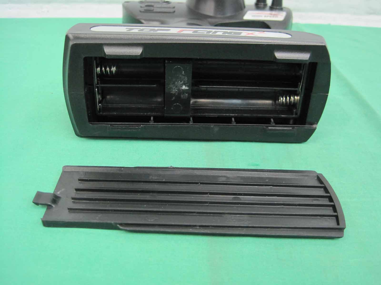
Click to zoom
Application Details
- Equipment Class
- DXX - Part 15 Low Power Communication Device Transmitter
- Date of Grant
- Oct 24, 2012
- Application Purpose
- Original Equipment
- Date of Application
- Oct 24, 2012
- Equipment Note
- 2.4 GHz R/C CAR
- Frequency Range
- 2405.00000000 - 2475.00000000
- Company
- CREATE TOYS FACTORY
- Country
- China
Documents & Files
Document Text
Text extracted from the exhibit documents filed with the FCC. Open a document above to read the original.
Users Manual
User Manual Note: This equipment has been tested and found to comply with the limits for a Class B digital device, pursuant to Part 15 of the FCC Rules. These limits are designed to provide reasonable protection against harmful interference in a residential installation. This equipment generates, uses and can radiate radio frequency energy and, if not installed and used in accordance with the instructions, may cause harmful interference to radio communications. However, there is no guarantee that interference will not occur in a particular installation. If this equipment does cause harmful interference to radio or television reception, which can be determined by turning the equipment off and on, the user is encouraged to try to correct the interference by one or more of the following measures: -- Reorient or relocate the receiving antenna. -- Increase the separation between the equipment and receiver. -- Connect the equipment into an outlet on a circuit different from that to which the receiver is connected. -- Consult the dealer or an experienced radio/TV technician for help. The manufacturer is not responsible for any radio or TV interference caused by unauthorized modifications to this equipment such modifications could void the user authority to operate the equipment. Changes or modifications not expressly approved by the party responsible for compliance could void the user’s authority to operate the equipment. This device complies with Part 15 of the FCC Rules. Operation is subject to the following two conditions: (1) This device may not cause harmful interference, and (2) This device must accept any interference received, including interference that may cause undesired operation. Warning: Changes or modifications to this unit not expressly approved by the party responsible for compliance could void the user's authority to operate the equipment.
Block Diagram
6004 -2.4GCOB-1 Transmitter Block Diagram : ANT MCU 2.4G COB-1 DC POWER SUPPLY data SPI communication
ID Label/Location Info
Size: 32mm X 12mm Label Artwork
Operational Description
All rights reserved. Reproduction in whole or in part is prohibited without the prior written permission of the copyright holder. July 2007 nRF24L01 Single Chip 2.4GHz Transceiver Product Specification Key Features •Worldwide 2.4GHz ISM band operation •Up to 2Mbps on air data rate •Ultra low power operation •11.3mA TX at 0dBm output power •12.3mA RX at 2Mbps air data rate •900nA in power down •22μA in standby-I •On chip voltage regulator •1.9 to 3.6V supply range •Enhanced ShockBurst™ •Automatic packet handling •Auto packet transaction handling •6 data pipe MultiCeiver™ •Air compatible with nRF2401A, 02, E1 and E2 •Low cost BOM •±60ppm 16MHz crystal •5V tolerant inputs •Compact 20-pin 4x4mm QFN package Applications •Wireless PC Peripherals •Mouse, keyboards and remotes •3-in-one desktop bundles •Advanced Media center remote controls •VoIP headsets •Game controllers •Sports watches and sensors •RF remote controls for consumer electronics •Home and commercial automation •Ultra low power sensor networks •Active RFID •Asset tracing systems •Toys Revision 2.0 Page 2 of 74 nRF24L01 Product Specification Liability disclaimer Nordic Semiconductor ASA reserves the right to make changes without further notice to the product to improve reliability, function or design. Nordic Semiconductor ASA does not assume any liability arising out of the application or use of any product or circuits described herein. All application information is advisory and does not form part of the specification. Limiting values Stress above one or more of the limiting values may cause permanent damage to the device. These are stress ratings only and operation of the device at these or at any other conditions above those given in the specifications are not implied. Exposure to limiting values for extended periods may affect device reliability. Life support applications These products are not designed for use in life support appliances, devices, or systems where malfunction of these products can reasonably be expected to result in personal injury. Nordic Semiconductor ASA cus- tomers using or selling these products for use in such applications do so at their own risk and agree to fully indemnify Nordic Semiconductor ASA for any damages resulting from such improper use or sale. Contact details Visit www.nordicsemi.no for Nordic Semiconductor sales offices and distributors worldwide Main office: Otto Nielsens vei 12 7004 Trondheim Phone: +47 72 89 89 00 Fax: +47 72 89 89 89 www.nordicsemi.no Data sheet status Objective product specificationThis product specification contains target specifications for product development. Preliminary product specification This product specification contains preliminary data; supplementary data may be published from Nordic Semiconductor ASA later. Product specificationThis product specification contains final product specifications. Nordic Semiconductor ASA reserves the right to make changes at any time without notice in order to improve design and supply the best possible product. Revision 2.0 Page 3 of 74 nRF24L01 Product Specification Writing Conventions This product specification follows a set of typographic rules that makes the document consistent and easy to read. The following writing conventions are used: •Commands, bit state conditions, and register names are written in Courier. •Pin names and pin signal conditions are written in Courier bold. •Cross references are underlined and highlighted in blue . Revision History DateVersionDescription July 20072.0 •Restructured layout in a new template •Added details of the following features: XDynamic Payload Length (DPL) XAcknowledgement Payload (ACK_PLD) XFeature register XACTIVATE SPI command XSelective Auto Acknowledgement (NO_ACK) Revision 2.0 Page 4 of 74 nRF24L01 Product Specification Contents 1Introduction ............................................................................................... 7 1.1Features ............................................................................................... 8 1.2Block diagram ...................................................................................... 9 2Pin Information .......................................................................................... 10 2.1Pin assignment..................................................................................... 10 2.2Pin functions......................................................................................... 11 3Absolute maximum ratings ...................................................................... 12 4Operating conditions ................................................................................ 13 5Electrical specifications ........................................................................... 14 5.1Power consumption.............................................................................. 14 5.2General RF conditions ......................................................................... 15 5.3Transmitter operation ........................................................................... 15 5.4Receiver operation ............................................................................... 16 5.5Crystal specifications ........................................................................... 17 5.6DC characteristics ................................................................................ 18 5.7Power on reset ..................................................................................... 18 6Radio Control ............................................................................................ 19 6.1Operational Modes ............................................................................... 19 6.1.1State diagram .................................................................................. 19 6.1.2Power Down Mode .......................................................................... 20 6.1.3Standby Modes.......................................................…
Text truncated - open the document above for the full version.
Operational Description
The 2.4GHz Module is a single chip 2.4GHz transceiver with an embedded baseband protocol engine , designed for ultra low power wireless applications. The 2.4GHz Module is designed for operation in the world wide ISM frequency band at 2.400 - 2.4835GHz. An MCU (microcontroller) and very few external passive components are needed to design a radio system with the nRF24L01. The 2.4GHz Module is configured and operated through a Serial Peripheral Interface. Through this inter- face the register map is available. The register map contains all configuration registers in the 2.4GHz Module and is accessible in all operation modes of the chip. The embedded baseband protocol engine is based on packet communication and supports various modes from manual operation to advanced autonomous protocol operation. Internal FIFOs ensure a smooth data flow between the radio front end and the system’s MCU. reduces system cost by handling all the high-speed link layer operations. The radio front end uses GFSK modulation. It has user configurable parameters like frequency channel, output power and air data rate. The air data rate supported by the 2.4GHz Module is configurable to 2Mbps. The high air data rate combined with two power saving modes makes the 2.4GHz Module very suitable for ultra low power designs. Internal voltage regulators ensure a high Power Supply Rejection Ratio (PSRR) and a wide power supply range. Technical Description
Schematics
1 2 3 4 5 6 ABCD 6 5 4 3 2 1 D CBA Title Number Revision Size B Date: 19-Mar-2012 Sheet of File: F:\XU\2.4G\2.4G 方方 .Ddb Drawn By: CE 1 CSN 2 SCK 3 MOSI 4 MISO 5 IRQ 6 VDD 7 VSS 8 XTALP 9 XTALN 10 VDDPA 11 RFP 12 RFN 13 VSS 14 VDD 15 IREF 16 VSS 17 VDD 18 CDVDD 19 VSS 20 1 3.3V CSNSCK MOSIMISO IRQ L2 6.8NH L1 8.2NH L3 3.9NH R3 1M C818P C718P C2 4.7P C42.2P C51.2P C3104 Y116M R222K C1333 E1ANTENNA CE 深深深深深深深深 2.4G RF 深电电 V1.0 C7 105
Test Report
Address: Units 303-305, 3/F., 31 Lok Yip Road, On Lok Tsuen, Fanling, N.T., Hong Kong Telephone: +852 23052570 Fax: +852 27564480 Email: [email protected] Report No.: 57817 Page: 1 of 25 Authorized Signature: Stephen C.N. Wong Technical Manager The manufacturer should ensure that all products in series production are in conformity with the product sample detailed in this report. If the product in this report is used in any configuration other than that detailed in the report, the manufacturer must ensure the new system complies with all relevant standards. Any mention of SGS IECC Limited or testing done by SGS IECC Limited in connection with, distribution or use of the product described in this report must be approved by SGS IECC Limited in writing. This document is issued by the Company subject to its General Conditions of Service printed overleaf, available on request or accessible at www.sgs.com/terms_and_conditions.htm and, for electronic format documents, subject to Terms and Conditions for Electronic Documents at www.sgs.com/terms_e-document.htm . Attention is drawn to the limitation of liability, indemnification and jurisdiction issues defined therein. Any holder of this document is advised that information contained hereon reflects the Company’s findings at the time of its intervention only and within the limits of Client’s instructions, if any. The Company’s sole responsibility is to its Client and this document does not exonerate parties to a transaction from exercising all their rights and obligations under the transaction documents. This document cannot be reproduced except in full, without prior written approval of the Company. Any unauthorized alteration, forgery or falsification of the content or appearance of this document is unlawful and offenders may be prosecuted to the fullest extent of the law. Unless otherwise stated the results shown in this test report refer only to the sample(s) tested and such sample(s) are retained for 90 days only . Member of the SGS Group (SGS SA) FCC Test Report Application No.: 57817 Applicant: CREATE TOYS FACTORY Address: 1-2 Floor, No. 6 Building, Longtian Guanghua Industrial Park Chengjiang Road, Chenghai District, Shantou City, Guangdong China Product Information: Product Description: R/C Series Model: 6003, 6004, 6005, 6006, 6007, 6008, 6009, 6910, 6011, 6012, 6013, 6014, 3372, 3382, 3392 ♣ ♣ Please refer to section 2 of this report which indicates which item was actually tested and which were electrically identical. Product Class : Low Power Communication Device – Transmitter (2.4 GHz) FCC ID number: YEJSHENQIWEI-5 Requirement: CFR 47 FCC PART 15 SUBPART C, 2011 - Intentional Radiators. Date of Receipt: August 31, 2012 Date of Test: September 10, 2012 to September 12, 2012 October 25, 2012 Date of Issue: October 25, 2012 Test Result : PASS* * In the configuration tested, the EUT complied with the requirements for the relevant clauses of Federal Communications Commission Rules as specified above. Report No.: 57817 Page: 2 of 25 This document is issued by the Company subject to its General Conditions of Service printed overleaf, available on request or accessible at www.sgs.com/terms_and_conditions.htm and, for electronic format documents, subject to Terms and Conditions for Electronic Documents at www.sgs.com/terms_e-document.htm . Attention is drawn to the limitation of liability, indemnification and jurisdiction issues defined therein. Any holder of this document is advised that information contained hereon reflects the Company’s findings at the time of its intervention only and within the limits of Client’s instructions, if any. The Company’s sole responsibility is to its Client and this document does not exonerate parties to a transaction from exercising all their rights and obligations under the transaction documents. This document cannot be reproduced except in full, without prior written approval of the Company. Any unauthorized alteration, forgery or falsification of the content or appearance of this document is unlawful and offenders may be prosecuted to the fullest extent of the law. Unless otherwise stated the results shown in this test report refer only to the sample(s) tested and such sample(s) are retained for 90 days only . Member of the SGS Group (SGS SA) 2 Test Summary Test Test Requirement Test Method Result Conducted Emission (150KHz to 30MHz) FCC PART 15, SUBPART C: 2011 ANSI C63.4:2003 N/A 1) Radiated Emission below 30MHz FCC PART 15, SUBPART C: 2011 ANSI C63.4:2003 PASS Radiated Emission (30MHz to 1GHz) FCC PART 15, SUBPART C: 2011 ANSI C63.4:2003 PASS Radiated Emission above 1 GHz FCC PART 15, SUBPART C: 2011 ANSI C63.4:2003 PASS Band edge / 20 dB Bandwidth FCC PART 15, SUBPART C: 2011 ANSI C63.4:2003 PASS Remark : 1) Please refer to section 6.1 of this report for explanation ♣ Item no.: 6003, 6004, 6005, 6006, 6007, 6008, 6009, 6910, 6011, 6012, 6013, 6014, 3372, 3382, 3392 According to the confirmation from the applicant, the above models are identical in all electrical aspects in relating to the circuit design, PCB layout, electrical components used, internal wiring and function. The differences are only the color and decorations. Therefore only the model 6004 was tested in this report. Report No.: 57817 Page: 3 of 25 This document is issued by the Company subject to its General Conditions of Service printed overleaf, available on request or accessible at www.sgs.com/terms_and_conditions.htm and, for electronic format documents, subject to Terms and Conditions for Electronic Documents at www.sgs.com/terms_e-document.htm . Attention is drawn to the limitation of liability, indemnification and jurisdiction issues defined therein. Any holder of this document is advised that information contained hereon reflects the Company’s findings at the time of its intervention only and within the limits of Client’s instructions, if any. The Company’s sole responsibility is to its Client and this document does not exonerate pa…
Text truncated - open the document above for the full version.
Contact Information
Applicant
XiuNa Xu(Sales Manager)
Test Firm
SGS IECC LimitedJeffery Chen
Technical Specifications
| # | Rule Parts | Frequency Range | Power Output |
|---|---|---|---|
| 1 | 15C | 2.40 GHz - 2.48 GHz | - |
Other Applications from CREATE TOYS FACTORY
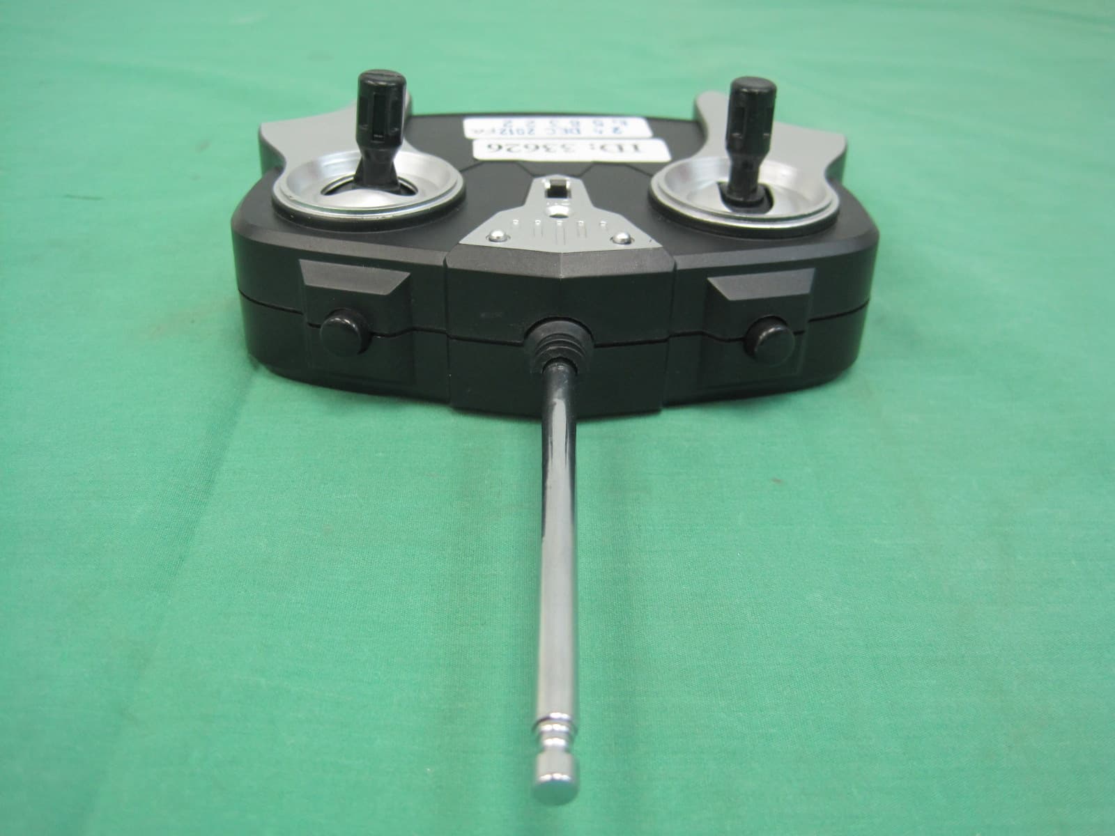
YEJSHENQIWEI-6
Feb 05, 2013R/C Boat
Equipment Class
DXX - Part 15 Low Power Communication Device Transmitter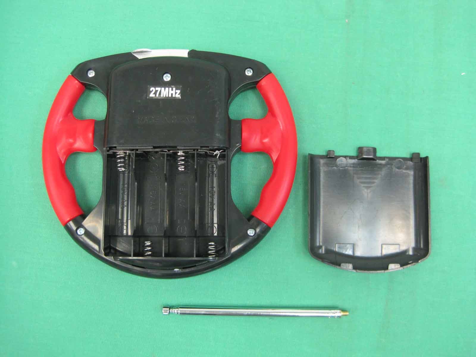
YEJSHENQIWEI-4
Aug 05, 201227 MHz R/C CAR
Equipment Class
DXX - Part 15 Low Power Communication Device Transmitter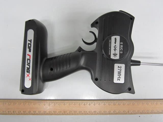
YEJSHENQIWEI-3
Oct 16, 2011RC Toy Transmitter
Equipment Class
DXX - Part 15 Low Power Communication Device Transmitter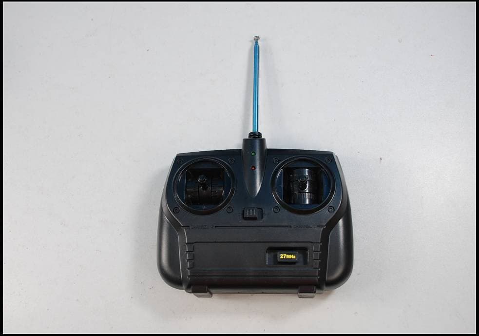
YEJSHENQIWEI-1
Jul 25, 2010R/C BOAT SERIES
Equipment Class
DXX - Part 15 Low Power Communication Device Transmitter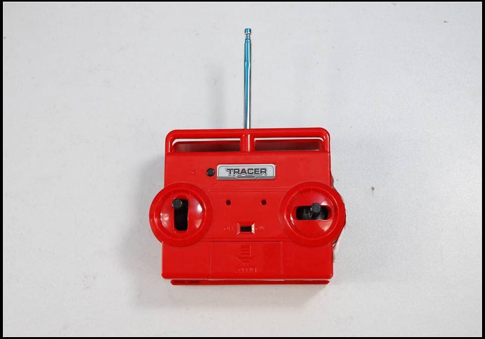
YEJSHENQIWEI-2
Jul 25, 2010R/C BOAT SERIES
Equipment Class
DXX - Part 15 Low Power Communication Device Transmitter