YETA71-JV4Smart Server Antenna
Nextivity Incorporated
Click to zoom
Application Details
- Equipment Class
- DTS - Digital Transmission System
- Date of Grant
- Oct 02, 2023
- Application Purpose
- Original Equipment
- Date of Application
- Oct 02, 2023
- Equipment Note
- Smart Server Antenna
- Frequency Range
- 2402.00000000 - 2480.00000000
- Company
- Nextivity Incorporated
- Country
- United States
Documents & Files
Document Text
Text extracted from the exhibit documents filed with the FCC. Open a document above to read the original.
Users Manual
CeilingCeiling Smart Server Antenna CEL-FI or SHIELD Signal Source Smart Server AntennaSmart Server Antenna Power Inserter Power Inserter Power Inserter CeilingCeiling Smart Server Antenna CEL-FI or SHIELD Signal Source Smart Server AntennaSmart Server Antenna Power Inserter Power Inserter Power Inserter The Smart Server Antenna is an active , omnidirectional antenna that is compatible with select CEL-FI and SHIELD products. Installation is easy on hard and dropped ceilings. Integration and alarms are accessible via WAVE software. SMART SERVER ANTENNA Quick Start Guide Low Profile Omnidirectional Antenna The Smart Server Antenna is an active , omnidirectional antenna that is compatible with select CEL-FI and SHIELD products. Installation is easy on hard and dropped ceilings. Integration and alarms are accessible via WAVE software. SMART SERVER ANTENNA Quick Start Guide Low Profile Omnidirectional Antenna Review the latest authorized antennas at: www.nextivityinc.com/antennas/smart-server-antenna 420N007-A71-001-01-RA Connection Diagram Copyright © 2023 by Nextivity, Inc., U.S. Patents pending. All rights reserved. The Nextivity and CEL-FI logos are registered trademarks of Nextivity, Inc. All other trademarks or registered trademarks listed belong to their respective owners. Designed by Nextivity, Inc. in California. qsg_active-server-antenna_23-0915 DC Cable Coax DC Cable DC Cable CoaxCoax Coupler KIT#: A71-PV4-C00 A71-JV4-C00 A71-JV7-C00 Review the latest authorized antennas at: www.nextivityinc.com/antennas/smart-server-antenna 420N007-A71-001-01-RA Connection Diagram Copyright © 2023 by Nextivity, Inc., U.S. Patents pending. All rights reserved. The Nextivity and CEL-FI logos are registered trademarks of Nextivity, Inc. All other trademarks or registered trademarks listed belong to their respective owners. Designed by Nextivity, Inc. in California. qsg_active-server-antenna_23-0915 DC Cable Coax DC Cable DC Cable CoaxCoax Coupler KIT#: A71-PV4-C00 A71-JV4-C00 A71-JV7-C00 CouplerCoupler CouplerCoupler Included In the Box Smart Server Antenna Power Inserter Dropped Ceiling Mounting Plate Fixing Nut Mounting Screws (4) Drywall Anchors (4) Hard Ceiling Mounting Plate 3x M3 x 6mm Screws QR Code Included In the Box Smart Server Antenna Power Inserter Dropped Ceiling Mounting Plate Fixing Nut Mounting Screws (4) Drywall Anchors (4) Hard Ceiling Mounting Plate 3x M3 x 6mm Screws QR Code Power Inserter Power Inserter STEP 5: Thread the DC Power cable through the Fixing Nut above the ceiling and down through the hole. Continue by guiding it through the center of the Dropped Ceiling Mounting Plate, ensuring that the DC cable wires extend with sufficient length for easy connection to the DC wire terminal block on the antenna. DROPPED CEILING INSTALL HARD CEILING INSTALL Antenna Installation STEP 1: Connect the Power Inserter to the signal source cable before each splitter/coupler/tapper in the Distributed Antenna System (DAS). A typical directional coupler example is shown below. STEP 2: Route the DC and coax cables to the Smart Server Antenna. Add a separate DC extension cable if needed to reach the desired Smart Server Antenna installation location. D) Insert the stripped negative wire into the negative wire slot and release the button. Gently pull-test the wire to make sure that it is firmly connected to the terminal block. STEP 3: Drill a 2-inch (50 mm) diameter hole in the dropped ceiling at the desired Smart Server Antenna location. NOTE: If installing on a hard ceiling, go to Step 3 in the "HARD CEILING INSTALL" section. STEP 4: Feed the antenna coax cable up through the Dropped Ceiling Mounting Plate and attach the Dropped Ceiling Mounting Plate to the back of the Smart Server Antenna using the three M3 Screws and a 2 mm hex wrench. STEP 7: Repeat Step 6 for the positive wire. STEP 6: Depress the negative wire spring button on the antenna DC wire terminal block, insert the stripped negative wire into the slot, and release the button. Gently pull-test the wire to make sure that it is firmly connected. STEP 8: Feed the antenna assembly and cabling up through the drilled ceiling hole in Step 3, and screw the Fixing Nut onto the Dropped Ceiling Mounting Plate threads to secure the antenna to the dropped ceiling. STEP 3: Place the Hard Ceiling Mounting Plate against the ceiling, oriented so the cables will exit the antenna in the desired direction along the flat edge of the plate. Then mark the three holes for the Drywall Anchors. STEP 9: Connect the antenna coax cable to the signal source coax cable. STEP 7: Align the plastic clips on the Hard Ceiling Mounting Plate with the three holes on the antenna and snap the antenna onto the plate in the direction of the cable groove. STEP 8: Connect the antenna coax cable to the signal source cable, being careful not to pull on the antenna coax cable connector. Plastic Clips STEP 6: Connect the DC cable wires to the DC wire terminal block as shown in DROPPED CEILING INSTALL Steps 6 and 7. Then place the DC cable and antenna coax cable into the groove, being careful not to pull on the RF connector. STEP 4: Drill the three holes for the supplied Drywall Anchors. STEP 5: Insert the Drywall Anchors into the drilled holes and use the Mounting Screws to secure the Hard Ceiling Mounting Plate to the ceiling. STEP 5: Thread the DC Power cable through the Fixing Nut above the ceiling and down through the hole. Continue by guiding it through the center of the Dropped Ceiling Mounting Plate, ensuring that the DC cable wires extend with sufficient length for easy connection to the DC wire terminal block on the antenna. DROPPED CEILING INSTALL HARD CEILING INSTALL Antenna Installation STEP 1: Connect the Power Inserter to the signal source cable before each splitter/coupler/tapper in the Distributed Antenna System (DAS). A typical directional coupler example is shown below. STEP 2: Route the DC and coax cables to the Smart Server Antenna. Add a separate DC extensi…
Text truncated - open the document above for the full version.
Users Manual
CAUTION •Use Smart Server Antenna indoors. It should not be used outdoors. •The server antenna(s) MUST be installed to ensure a minimum of 8 in (20 cm) separation distance from persons from the human body. •These products are designed to only be used with CEL- FI or SHIELD family products. All the requirements of the manufacturer must be met when installing the antenna. •There are no user-serviceable parts inside. •Changes or modifications to this product not expressly approved by Nextivity may void your right to operate the equipment. There are no user-serviceable parts inside. •This device may be operated ONLY in a fixed location for in-building use. Warranty Nextivity, Inc. provides a limited warranty for its products. For details, please refer to nextivityinc.com/warranty/. Limitation of Liability In no event shall NEXTIVITY, nor its directors, employees, agents, suppliers or End Users be liable under contract, tort, strict liability, negligence, or any other legal or equitable theory with respect to the Products or any other subject matter of this Agreement (i) for any lost profits, cost of procurement of substitute goods or services, or special, indirect, incidental, punitive, or consequential damages of any kind whatsoever or (ii) for any direct damages in excess of (in the aggregate) the fees actually received by NEXTIVITY from End User with respect to the Products actually purchased and paid for. Warning E911 location information may not be provided or inaccurate for calls served by this device. Regulatory Information: US FCC Statement This equipment has been tested and found to comply with the limits for a Class B digital device, pursuant to part 15 of the FCC Rules. These limits are designed to provide reasonable protection against harmful interference in a residential installation. This equipment generates, uses, and can radiate radio frequency energy and, if not installed and used in accordance with the instructions, may cause harmful interference to radio communications. However, there is no guarantee that interference will not occur in a particular installation. If this equipment does cause harmful interference to radio or television reception, which can be determined by turning the equipment off and on, the user is encouraged to try to correct the interference by one or more of the following measures: •Reorient or relocate the receiving antenna. •Increase the separation between the equipment and receiver. •Connect the equipment into an outlet on a circuit different from that to which the receiver is connected. •Consult the dealer or an experienced radio/TV technician for help. This device complies with part 15 of the FCC Rules. Operation is subject to the following two conditions: •1. This device may not cause harmful interference, and •2. This device must accept any interference received, including interference that may cause undesired operation. Regulatory Information: Canada This device complies with Industry Canada license-exe mpt RSS standard(s). Operation is subject to the following two conditions: •This device may not cause interference, and •This device must accept any interference, including interference that may cause undesired operation of the device. FRENCH: Le présent appareil est conforme aux CNR d’Industrie Canada applicables aux appareils radio exempts de li-cence. L’exploitation est autorisée aux deux conditions suivantes: •L’appareil ne doit pas produire de brouillage, et •L’utilisateur de l’appareil doit accepter tout brouillage radioélectrique subi, même si le brouillage est suscep- tible d’en compromettre le fonctionnement. Compliance Contact In the event of a regulatory compliance issue, please get in touch with Nextivity, Inc. directly. Nextivity, Inc. can be contacted at nextivityinc.com/contact. Trademark CEL-FI and Nextivity logo are trademarks of Nextivity, Inc. Patents This product is covered by Nextivity, Inc., US patents and patents pending. Please refer to http://www.nextivityinc. com for details. Copyright Copyright © 2023 by Nextivity, Inc. All rights reserved. Reproduction or media conversion by any means is protected by copyright and may only occur with the prior written permission of Nextivity. Designed by Nextivity in California. CAUTION •Use Smart Server Antenna indoors. It should not be used outdoors. •The server antenna(s) MUST be installed to ensure a minimum of 8 in (20 cm) separation distance from persons from the human body. •These products are designed to only be used with CEL- FI or SHIELD family products. All the requirements of the manufacturer must be met when installing the antenna. •There are no user-serviceable parts inside. •Changes or modifications to this product not expressly approved by Nextivity may void your right to operate the equipment. There are no user-serviceable parts inside. •This device may be operated ONLY in a fixed location for in-building use. Warranty Nextivity, Inc. provides a limited warranty for its products. For details, please refer to nextivityinc.com/warranty/. Limitation of Liability In no event shall NEXTIVITY, nor its directors, employees, agents, suppliers or End Users be liable under contract, tort, strict liability, negligence, or any other legal or equitable theory with respect to the Products or any other subject matter of this Agreement (i) for any lost profits, cost of procurement of substitute goods or services, or special, indirect, incidental, punitive, or consequential damages of any kind whatsoever or (ii) for any direct damages in excess of (in the aggregate) the fees actually received by NEXTIVITY from End User with respect to the Products actually purchased and paid for. Warning E911 location information may not be provided or inaccurate for calls served by this device. Regulatory Information: US FCC Statement This equipment has been tested and found to comply with the limits for a Class B digital device, pursuant to part 15 of the FCC Rules. These limits are designed to prov…
Text truncated - open the document above for the full version.
Attestation Statements
16550 West Bernardo Drive, Suite 550, San Diego, CA 92127, USA Tel: +1 858.485.9942 Date: Sept 10, 2023 Federal Communications Commission 7435 Oakland Mills Road Columbia, MD 21046 USA Ref: Attestation Statements Part 2.911(d)(5)(i) and Part 2.911(d)(5)(ii) Filing Re. KDB 986446 D01(FCC ID: YETA71-JV4) To whom it may concern: Nextivity, Inc. (“the applicant”) certifies that the equipment for which authorization is sought is not “covered” equipment prohibited from receiving an equipment authorization pursuant to section 2.903 of the FCC rules. We also certify that, as of the date of the filing of the application, the applicant is not identified on the Covered List as an entity producing “covered” equipment. If you have any questions, please contact us. Yours sincerely, C K Li, Technical Director of Regulatory Name, function, signature
Attestation Statements
16550 West Bernardo Drive, Suite 550, San Diego, CA 92127, USA Tel: +1 858.485.9942 Date: Sept 10, 2023 Federal Communications Commission 7435 Oakland Mills Road Columbia, MD 21046 USA Ref: Attestation Statements Part 2.911(d)(7) Filing (ID: YETA71-JV4) To whom it may concern: Nextivity, Inc. (“the applicant”) certifies that, as of the date of the filing of the application, Nextivity, Inc. is our designated U.S. agent for service of process for the above referenced FCC ID. Nextivity, Inc. accepts to maintain an agent for no less than one year after the grantee has terminated all marketing and importation or the conclusion of any Commission-related proceeding involving the equipment. Nextivity Inc. accepts, as of the date of the filing of the application, the obligation of the designated U.S. agent for service of process for the above referenced FCC ID. Designated U.S. Agent Information: Name: Nextivity, Inc. Address: 16550 West Bernardo Drive, Suite 550, San Diego, CA 92127, USA Contact Person: C K Li Tel.: 1-858-485-9442 Email: [email protected] FRN: 0019823665 Sincerely, C K Li Applicant and U.S. agent
Cover Letter(s)
16550 West Bernardo Drive, Suite 550, San Diego, CA 92127, USA Tel: +1 858.485.9942 Date: Sept 10, 2023 Federal Communications Commission Equipment Authorization Branch 7435 Oakland Mills Road Columbia, MD 21046 Confidentiality Request FCC ID: YETA71-JV4 Pursuant to Sections 0.457(d)(1)(ii) and 0.459 of the Commission’s Rules, Nextivity Incorporated hereby requests permanent confidential treatment of information accompanying this application as outlined below: • Schematics • Bill of Materials/Parts List • Block Diagrams • Theory of Operation • Tune-up Procedure Nextivity Incorporated also hereby requests short-term confidential treatment of information accompanying this application as outlined below for a period of period of 180 days: • Internal Photos • External Photos • User Manual and Legal Insert • Test Set-up Photos The above materials contain trade secrets and proprietary information not customarily released to the public. The public disclosure of these matters might be harmful to the Applicant and provide unjustified benefits to its competitors. The Applicant understands that pursuant to Rule 0.457(d)(1)(ii), disclosure of this Application and all accompanying materials will not be made before the date of the Grant for this Application. Yours sincerely, C K Li, Technical Director of Regulatory Name, function, signature
External Photos
FCC ID: YETA71-JV4 Nextivity Inc., Proprietary and Confidential 1 of 2 02 External Photos 16550 West Bernardo Drive, Suite 550, San Diego, CA 92127, USA Tel: +1 858.485.9442 • Fax: +1 858.485.9445 http://www.cel-fi.com External Photos CEL-FI Model #: A71-JV4 Top Bottom FCC ID: YETA71-JV4 Nextivity Inc., Proprietary and Confidential 2 of 2 02 External Photos 16550 West Bernardo Drive, Suite 550, San Diego, CA 92127, USA Tel: +1 858.485.9442 • Fax: +1 858.485.9445 http://www.cel-fi.com Side 1 Side 2
ID Label/Location Info
Label Size: 2” x 1” Product Label (A71-JV4) Label Location
Internal Photos
FCC ID: YETA71-JV4 Nextivity Inc., Proprietary and Confidential 1 of 2 08 Internal Photos 16550 West Bernardo Drive, Suite 550, San Diego, CA 92127, USA Tel: +1 858.485.9442 • Fax: +1 858.485.9445 http://www.cel-fi.com Internal Photos CEL-FI Model #: A71-JV4 View 1 View 2 FCC ID: YETA71-JV4 Nextivity Inc., Proprietary and Confidential 2 of 2 08 Internal Photos 16550 West Bernardo Drive, Suite 550, San Diego, CA 92127, USA Tel: +1 858.485.9442 • Fax: +1 858.485.9445 http://www.cel-fi.com PCB 1 Side 2
RF Exposure Info
TÜV SÜD AMERICA INC 10040 Mesa Rim Road San Diego, CA 92121-2912 Phone: 858 678 1400 FAX: 858 546 0364 August 25, 2023 TUV SUD America CB 10 Centennial Drive FL2 Peabody, MA 01960 Attention: Director of Certification RE: Analysis of RF Exposure for Mobile and Portable Device per KDB 447498 D01 General RF Exposure Guidance v06 and RSS-102 Issue 5 March 2015. FCC ID: YETA71-JV4 IC Number: 9892A-A71JV4 1. Limits Limits for General Population/Uncontrolled Exposure (Title 47 Subpart J §2.1091 and KDB 447498 D01 referring to limits under §1.1310) Frequency Range (MHz) Electric Field Strength (E) (V/m) Electric Field Strength (H) (A/m) Power Density (S) (mW/cm 2 ) Averaging Time (minutes) 0.3 - 1.34 614 1.63 *(100) 30 1.34 - 30 824/f 2.19/f *(180/f 2 ) 30 30 - 300 27.5 0.073 0.2 30 300 - 1500 - - f/1500 30 1500 - 100,000 - - 1.0 30 f = frequency in MHz *Plane-wave equivalent power density 2. ISED Limits: Limits for Devices Used by the General Public (Uncontrolled Environment (RSS-102 Issue 5 March 2015) Frequency Range (MHz) Electric Field Strength (V/m rms) Magnetic Field (A/m rms) Power Density (W/m 2 ) Reference Period (minutes) 0.003 - 10 21 83 90 - Instantaneous 0.1 - 10 - 0.73/f - 6** 1.1 - 10 87/f 0.5 - - 6** 10 - 20 27.46 0.0728 2 6 20 - 48 -58.07/f 0.25 0.1540/f 0.25 8.944/f 0.5 6 48 - 300 22.06 0.05852 1.291 6 300 - 6000 3.142 f 0.3417 0.008335 f .0.3417 0.02619 f 0.6834 6 TÜV SÜD AMERICA INC 10040 Mesa Rim Road San Diego, CA 92121-2912 Phone: 858 678 1400 FAX: 858 546 0364 6000 - 15000 61.4 0.163 10 6 15000 - 150000 61.4 0.163 10 616000/f 1.2 150000 - 300000 0.158f 0.5 4.21 x 10 .-4 f 0.5 6.67 x 10 .-5 f 616000/f 1.2 f is frequency in MHz *Based on nerve stimulation (NS) ** Based on specific absorption rate (SAR) 3. Mobile MPE Calculation using a 20cm separation distance: Using Power Density formula: S= PG 4πR 2 where: S = power density P = power input to the antenna G = power gain of the antenna in the direction of interest relative to isotropic R = distance to the center of radiation of the antenna Maximum output power at antenna input terminal: 3.80 (dBm) Maximum output power at antenna input terminal: 2.40 (mW) Antenna gain(typical): 1.3 (dBi) Maximum antenna gain: 1.349 (numeric) Prediction distance: 20 (cm) Source Based Time Average Duty Cycle: 100 (%) Prediction frequency: 2440 (MHz) MPE limit for uncontrolled exposure at prediction frequency: 0.541 (mW/cm 2 ) Power density at prediction frequency: 0.00064 (mW/cm 2 ) Power density at prediction frequency: 0.006 (W/m 2 ) Margin of Compliance: -29.24 (dB) Calculation Note: ISED calculation only presented as FCC limit at this frequency is less stringent (1.0 mW/cm 2 ). Margin of compliance is -31.91dB for FCC and -29.24dB for ISED. Sincerely, Ferdie S. Custodio Name Authorized Signatory Title: Senior EMC Test Engineer /Wireless Team Lead
Test Report
TÜV SÜD America, Inc. 10040 Mesa Rim Road San Diego, CA 92121-2912 TÜV SÜD America, Inc. Rancho Bernardo Facility 16936 Via Del Campo San Diego, CA 92127 Phone: 858 678 1400 www.TÜV-sud-america.com TÜV SÜD RESPONSIBLE FOR NAME TITLE DATE SIGNATURE Prepared By Ferdinand Custodio Wireless Team Lead September 28, 2023 Authorized Signatory Omar Castillo Senior RF/EMC Test Engineer September 28, 2023 Signatures in this approval box have checked this document in line with the requirements of TÜV SÜD Product Service document control rules. EXECUTIVE SUMMARY A sample of this product was tested and found to be in compliance with FCC Part 15 Subpart C §15.247 and IC RSS-247 Issue 2 February 2017. Radio Testing of the Nextivity Inc. Bluetooth Transceiver Model: A71-JV4 In accordance with FCC Part 15 Subpart C §15.247 and IC RSS-247 Issue 2 February 2017 Prepared for: Nextivity Inc. 16550 West Bernardo Drive, Bldg 5, Suite 550 San Diego, CA 92127 USA COMMERCIAL-IN-CONFIDENCE Date: September 2023 Document Number: 72192194B Issue 01 | Version Number: 01 A2LA Cert. No. 2955.13 DISCLAIMER AND COPYRIGHT This report has been prepared by TÜV SÜD America with all reasonable skill and care. The document is confidential to the potential Client and TÜV SÜD America. No part of this document may be reproduced without the prior written approval of TÜV SÜD America. ACCREDITATION Our A2LA Accreditation does not cover opinions and interpretations and any expressed are outside the scope of our A2LA Accreditation. FCC ID: YETA71-JV4 IC: 9298A-A71JV4 Report No. 72192194B COMMERCIAL-IN-CONFIDENCE Page 2 of 72 REPORT ON TEST REPORT NUMBER TEST REPORT DATE Radio Testing of the Nextivity Inc. Model: Smart Server Antenna (Bluetooth Transceiver) 72192194B September 2023 PREPARED FOR Nextivity Inc. 16550 West Bernardo Drive, Bldg 5, Suite 550 San Diego, CA 92127 USA CONTACT PERSON CK Li Sr. Principal Engineer, Regulatory [email protected] +1 (858) 485-9442 PREPARED BY Ferdinand S. Custodio Name Authorized Signatory Title: Senior EMC Test Engineer / Wireless Team Lead APPROVED BY Omar Castillo Name Authorized Signatory Title: Senior EMC/Wireless Test Engineer DATED September 28, 2023 FCC ID: YETA71-JV4 IC: 9298A-A71JV4 Report No. 72192194B COMMERCIAL-IN-CONFIDENCE Page 3 of 72 Revision History 72192194B Nextivity Inc. Model: Smart Server Antenna DATE OLD REVISION NEW REVISION REASON PAGES AFFECTED APPROVED BY 09/28/2023 ― Initial Release Omar Castillo FCC ID: YETA71-JV4 IC: 9298A-A71JV4 Report No. 72192194B COMMERCIAL-IN-CONFIDENCE Page 4 of 72 CONTENTS Section Page No 1 REPORT SUMMARY ................................................................................................................... 5 1.2 Brief Summary of Results ............................................................................................................. 7 1.3 Product Information ...................................................................................................................... 8 1.4 EUT Test Configuration ................................................................................................................ 9 1.5 Deviations From The Standard ................................................................................................... 10 1.6 Modification Record .................................................................................................................... 12 1.7 Test Methodology ....................................................................................................................... 12 1.8 Test Facility Location .................................................................................................................. 12 1.9 Test Facility Registration ............................................................................................................ 12 2 TEST DETAILS .......................................................................................................................... 14 2.1 Peak Output Power..................................................................................................................... 15 2.2 Conducted Emissions ................................................................................................................. 19 2.3 99% Emission Bandwidth ........................................................................................................... 23 2.4 Minimum 6 dB RF Bandwidth ..................................................................................................... 27 2.5 Out-Of-Band Emissions - Conducted ......................................................................................... 31 2.6 Band-Edge Compliance of RF Conducted Emissions ................................................................ 39 2.7 Radiated Spurious Emissions ..................................................................................................... 44 2.8 Power Spectral Density .............................................................................................................. 53 3 TEST EQUIPMENT USED ......................................................................................................... 63 3.1 Test Equipment Used ................................................................................................................. 64 3.2 Measurement Uncertainty .......................................................................................................... 65 4 DIAGRAM OF TEST SETUP ..................................................................................................... 67 4.1 Test Setup Diagram .................................................................................................................... 68 5 ACCREDITATION, DISCLAIMERS AND COPYRIGHT ............................................................ 71 5.1 Accreditation, Disclaimers and Copyright ................................................................................... 72 FCC…
Text truncated - open the document above for the full version.
Test Setup Photos
FCC ID: YETA71-JV4 IC: 9298A-A71JV4 TÜV SÜD America, Inc., 10040 Mesa Rim Road, San Diego, CA 92121-2912 Test Setup Photos Exhibit Page 1 of 5 Conducted Emissions Test Setup FCC ID: YETA71-JV4 IC: 9298A-A71JV4 TÜV SÜD America, Inc., 10040 Mesa Rim Road, San Diego, CA 92121-2912 Test Setup Photos Exhibit Page 2 of 5 Radiated Emissions Test Setup (9kHz to 30MHz) FCC ID: YETA71-JV4 IC: 9298A-A71JV4 TÜV SÜD America, Inc., 10040 Mesa Rim Road, San Diego, CA 92121-2912 Test Setup Photos Exhibit Page 3 of 5 Radiated Emissions Test Setup (30MHz to 1GHz) FCC ID: YETA71-JV4 IC: 9298A-A71JV4 TÜV SÜD America, Inc., 10040 Mesa Rim Road, San Diego, CA 92121-2912 Test Setup Photos Exhibit Page 4 of 5 Radiated Emissions Test Setup (1GHz to 18GHz) FCC ID: YETA71-JV4 IC: 9298A-A71JV4 TÜV SÜD America, Inc., 10040 Mesa Rim Road, San Diego, CA 92121-2912 Test Setup Photos Exhibit Page 5 of 5 Radiated Emissions Test Setup (above 18GHz) FCC ID: YETA71-JV4 IC: 9298A-A71JV4 TÜV SÜD America, Inc., 10040 Mesa Rim Road, San Diego, CA 92121-2912 Test Setup Photos Exhibit Page 6 of 5 Antenna Conducted Port Test Setup
Contact Information
Applicant
Michiel Lotter(Vice President, Engineering)
Test Firm
TUV SUD America Inc.Mac Elliott
Technical Specifications
| # | Rule Parts | Frequency Range | Power Output |
|---|---|---|---|
| 1 | 15C | 2.40 GHz - 2.48 GHz | 2.40 mW |
Other Applications from Nextivity Incorporated
YETA91-JV4
Sep 12, 2024Smart Server Antenna
Equipment Class
DTS - Digital Transmission System
YETG41-CE
Jan 10, 2024Cellular Signal Booster with BLE
Equipment Class
B2I - Part 20 Industrial Booster (CMRS)
YETQ42-Z1CNU
May 05, 2023Provider-Specific Consumer Signal Booster
Equipment Class
B2P - Part 20 Provider-Specific Consumer Booster (CMRS)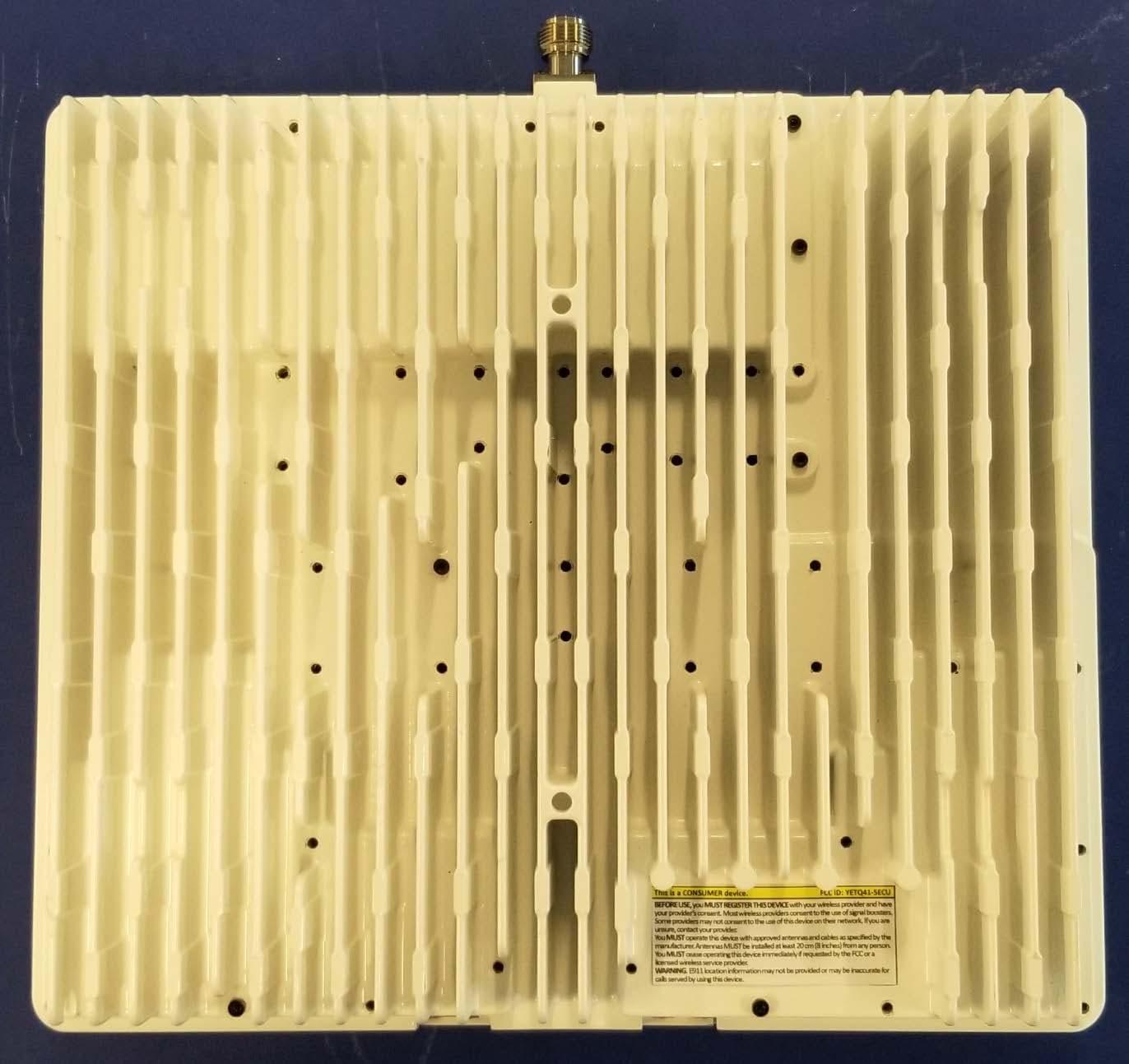
YETQ41-BXCU
May 05, 2023Provider-Specific Consumer Signal Booster
Equipment Class
B2P - Part 20 Provider-Specific Consumer Booster (CMRS)
YETQ44-1M34CNU
Feb 14, 2023Provider-Specific Consumer Signal Booster
Equipment Class
B2P - Part 20 Provider-Specific Consumer Booster (CMRS)