YETG41-CECellular Signal Booster with BLE
Nextivity Incorporated
Click to zoom
Application Details
- Equipment Class
- B2I - Part 20 Industrial Booster (CMRS)
- Date of Grant
- Jan 10, 2024
- Application Purpose
- Original Equipment
- Date of Application
- Jan 09, 2024
- Equipment Note
- Cellular Signal Booster with BLE
- Frequency Range
- 1930.00000000 - 1995.00000000
- Company
- Nextivity Incorporated
- Country
- United States
Documents & Files
Document Text
Text extracted from the exhibit documents filed with the FCC. Open a document above to read the original.
Users Manual
ISSUEACTION Unit cannot find a signal to boost (PWR LED blinks GREEN for over 10 minutes). • Check the WAVE App for error messages, and check that an operator has been selected in Settings. Check donor antenna, cable, connections, and aim antenna. You may have to wait up to one hour if the unit is powering up for the first time. WAVE App will not connect to the GO G41 FN. • Make sure Bluetooth is enabled on your phone. Restart Bluetooth. Reinstall/retry WAVE App. No LAN activity • The LAN port is only available to certified installers with WAVE Portal access. All other issues • Unplug and reinsert power. • Connect WAVE App for guidence. ISSUEACTION Unit cannot find a signal to boost (PWR LED blinks GREEN for over 10 minutes). • Check the WAVE App for error messages, and check that an operator has been selected in Settings. Check donor antenna, cable, connections, and aim antenna. You may have to wait up to one hour if the unit is powering up for the first time. WAVE App will not connect to the GO G41 FN. • Make sure Bluetooth is enabled on your phone. Restart Bluetooth. Reinstall/retry WAVE App. No LAN activity • The LAN port is only available to certified installers with WAVE Portal access. All other issues • Unplug and reinsert power. • Connect WAVE App for guidence. ⏻ LED MEANING Solid GREENThe unit is working and boosting properly. Blinking GREENUnit is scanning for networks to boost. Blinking RED- ORANGE Start-up sequence. Blinking or Solid RED The unit is in an error condition. Use the WAVE App to check the error meaning and remedy. LED OFFNo power. ⏻ LED MEANING Solid GREENThe unit is working and boosting properly. Blinking GREENUnit is scanning for networks to boost. Blinking RED- ORANGE Start-up sequence. Blinking or Solid RED The unit is in an error condition. Use the WAVE App to check the error meaning and remedy. LED OFFNo power. LED MEANING Solid GREENConnected with IP address. Blinking GREENPhysical link up, no IP address. Blinking REDPhysical connection, error condition. LED OFFNo connection. LED MEANING Solid GREENConnected with IP address. Blinking GREENPhysical link up, no IP address. Blinking REDPhysical connection, error condition. LED OFFNo connection. User Interface ⏻ LED and LAN LED to indicate status. User Interface ⏻ LED and LAN LED to indicate status. Troubleshooting Troubleshooting CEL-FI ® GO G41 FN Quick Start Guide CEL-FI ® GO G41 FN Quick Start Guide qsg-go-g41-fn_1-3-5-28L_eng_23-1023 qsg-go-g41-fn_1-3-5-28L_eng_23-1023 420N007-G41-001-14-RB 420N007-G41-001-14-RB Basic Functionality: The CEL-FI GO G41 FN connects to a Donor Antenna to receive signals from AT&T’s FirstNet cellular network. It amplifies the signals through one or more server antennas for coverage where needed. The donor antenna is placed where there is a strong signal, preferably outdoors and positioned high. A cable splitter can connect additional server antennas for wider coverage. The WAVE App for smartphones and tablets is used to apply settings, help aim the donor antenna, and monitor performance. Basic Functionality: The CEL-FI GO G41 FN connects to a Donor Antenna to receive signals from AT&T’s FirstNet cellular network. It amplifies the signals through one or more server antennas for coverage where needed. The donor antenna is placed where there is a strong signal, preferably outdoors and positioned high. A cable splitter can connect additional server antennas for wider coverage. The WAVE App for smartphones and tablets is used to apply settings, help aim the donor antenna, and monitor performance. How it Works: Enhances in-building FirstNet ® coverage. For kit options, antennas, or cables, contact distributor or visit www.nextivityinc.com. How it Works: Enhances in-building FirstNet ® coverage. For kit options, antennas, or cables, contact distributor or visit www.nextivityinc.com. Example Installation Example Installation Server Port Server Port Donor Port Donor Port Included in the Box (Antennas & Cabling Sold Separately) Included in the Box (Antennas & Cabling Sold Separately) Mounting Screws (4) Drywall Anchors (4) Mounting Screws (4) Drywall Anchors (4) GO G41 FN GO G41 FN AC Adapter AC Adapter KIT#: G41-CE-003 KIT#: G41-CE-003 Wideband Directional AntennaWideband Panel AntennaWhip AntennaIndoor Omni AntennaLP SISO Indoor Omni Antenna A32-V32-200A52-V32-100A21-100-100A11-V43-100A11-H43-201 Donor Antenna ✓✓✓ Server Antenna ✓✓✓✓ Wideband Directional AntennaWideband Panel AntennaWhip AntennaIndoor Omni AntennaLP SISO Indoor Omni Antenna A32-V32-200A52-V32-100A21-100-100A11-V43-100A11-H43-201 Donor Antenna ✓✓✓ Server Antenna ✓✓✓✓ Additional Information Additional Information REQUIRED HARDWARE NOTE: This package comes equipped with Mounting Screws and Drywall Anchors for mounting to standard drywall. Before installing, ensure there are no wires, other objects, or metal plates behind the drywall that may interfere with the anchors, screws, or mounted units. REQUIRED HARDWARE NOTE: This package comes equipped with Mounting Screws and Drywall Anchors for mounting to standard drywall. Before installing, ensure there are no wires, other objects, or metal plates behind the drywall that may interfere with the anchors, screws, or mounted units. SAFETY: Please use proper safety measures when working on a ladder, lift, or roof SAFETY: Please use proper safety measures when working on a ladder, lift, or roof Soft-Install Option: Before permanently mounting system components, temporarily place the antennas, GO G41 FN, and cables, allowing for changes while optimizing the set up using WAVE App guidance. Longer cables or different antennas may be available from your supplier, if needed. Soft-Install Option: Before permanently mounting system components, temporarily place the antennas, GO G41 FN, and cables, allowing for changes while optimizing the set up using WAVE App guidance. Longer cables or different antennas may be available from your supplier, if needed. Antenna Kitting: The followi…
Text truncated - open the document above for the full version.
Users Manual
CAUTION • Use CEL-FI GO G41 FN indoors. It should not be used outdoors. • The donor antenna(s) MUST be installed to ensure a minimum of 25.5 in (65 cm) separation distance from human body at all times. • The server antenna(s) MUST be installed to ensure a minimum of 8 in (20 cm) separation distance from persons from human body at all times. • These products are designed to be used with a di- rect plug-in power supply unit. When installing the equipment, all the requirements of the manufac- turer and the referenced standards must be met. • There are no user-serviceable parts inside. • Changes or modifications to this product not expressly approved by Nextivity may void your right to operate the equipment. There are no user- serviceable parts inside. • Only the antennas listed or approved by the manu- facturer can be used with GO G41 FN. • This device may be operated ONLY in a fixed loca- tion for in-building use. • Use of unauthorized antennas, cables, and/or cou- pling devices not conforming with ERP/EIRP and/ or indoor-only restrictions is prohibited. Warranty Nextivity, Inc provides a limited warranty for its prod- ucts. For details, please refer to nextivityinc.com/ waranty. Limitation of Liability In no event shall NEXTIVITY, nor its directors, employ- ees, agents, suppliers or End Users, be liable under contract, tort, strict liability, negligence or any other le- gal or equitable theory with respect to the Products or any other subject matter of this Agreement (i) for any lost profits, cost of procurement of substitute goods or services, or special, indirect, incidental, punitive, or consequential damages of any kind whatsoever or (ii) for any direct damages in excess of (in the aggregate) the fees actually received by NEXTIVITY from End User with respect to the Products actually purchased and paid for. WARNING E911 location information may not be provided or may be inaccurate for calls served by using this device. WARNING. This is NOT a CONSUMER device. It is designed for installation by FCC LICENSEES and QUALIFIED INSTALLERS. You MUST have an FCC LICENSE or express consent of an FCC Licensee to operate this device. You MUST register Part 90 Class B signal boosters(as defined in 47 CFR 90.219) online. Unauthorized use may result in significant forfeiture penalties, including penalties in excess of $100,000 for each continuing violation. Part 90 and Part 20 Signal Boosters THIS IS A 90.219 CLASS B DEVICE Regulatory Information: US FCC Statement This equipment has been tested and found to comply with the limits for a Class B digital device, pursuant to part 15 of the FCC Rules. These limits are designed to provide reasonable protection against harmful in- terference in a residential installation. This equipment generates, uses and can radiate radio frequency ener- gy and, if not installed and used in accordance with the instructions, may cause harmful interference to radio communications. However, there is no guarantee that interference will not occur in a particular installation. If this equipment does cause harmful interference to radio or television reception, which can be determined by turning the equipment off and on, the user is en- couraged to try to correct the interference by one or more of the following measures: • Reorient or relocate the receiving antenna. • Increase the separation between the equipment and receiver. • Connect the equipment into an outlet on a circuit different from that to which the receiver is con- nected. • Consult the dealer or an experienced radio/TV technician for help. This device complies with part 15 of the FCC Rules. Operation is subject to the following two conditions: 1. This device may not cause harmful interference, and 2. This device must accept any interference received, including interference that may cause undesired operation. CAUTION • Use CEL-FI GO G41 FN indoors. It should not be used outdoors. • The donor antenna(s) MUST be installed to ensure a minimum of 25.5 in (65 cm) separation distance from human body at all times. • The server antenna(s) MUST be installed to ensure a minimum of 8 in (20 cm) separation distance from persons from human body at all times. • These products are designed to be used with a di- rect plug-in power supply unit. When installing the equipment, all the requirements of the manufac- turer and the referenced standards must be met. • There are no user-serviceable parts inside. • Changes or modifications to this product not expressly approved by Nextivity may void your right to operate the equipment. There are no user- serviceable parts inside. • Only the antennas listed or approved by the manu- facturer can be used with GO G41 FN. • This device may be operated ONLY in a fixed loca- tion for in-building use. • Use of unauthorized antennas, cables, and/or cou- pling devices not conforming with ERP/EIRP and/ or indoor-only restrictions is prohibited. Warranty Nextivity, Inc provides a limited warranty for its prod- ucts. For details, please refer to nextivityinc.com/ waranty. Limitation of Liability In no event shall NEXTIVITY, nor its directors, employ- ees, agents, suppliers or End Users, be liable under contract, tort, strict liability, negligence or any other le- gal or equitable theory with respect to the Products or any other subject matter of this Agreement (i) for any lost profits, cost of procurement of substitute goods or services, or special, indirect, incidental, punitive, or consequential damages of any kind whatsoever or (ii) for any direct damages in excess of (in the aggregate) the fees actually received by NEXTIVITY from End User with respect to the Products actually purchased and paid for. WARNING E911 location information may not be provided or may be inaccurate for calls served by using this device. WARNING. This is NOT a CONSUMER device. It is designed for installation by FCC LICENSEES and QUALIFIED INSTALLERS. You MUST have an FCC LICENSE or express consent of an FCC Licensee to operate thi…
Text truncated - open the document above for the full version.
Attestation Statements
16550 West Bernardo Drive, Suite 550, San Diego, CA 92127, USA Tel: +1 858.485.9942 Date: Oct 30, 2023 Federal Communications Commission 7435 Oakland Mills Road Columbia, MD 21046 USA Ref: Attestation Statements Part 2.911(d)(7) Filing (ID: YETG41-CE) To whom it may concern: Nextivity, Inc. (“the applicant”) certifies that, as of the date of the filing of the application, Nextivity, Inc. is our designated U.S. agent for service of process for the above referenced FCC ID. Nextivity, Inc. accepts to maintain an agent for no less than one year after the grantee has terminated all marketing and importation or the conclusion of any Commission-related proceeding involving the equipment. Nextivity Inc. accepts, as of the date of the filing of the application, the obligation of the designated U.S. agent for service of process for the above referenced FCC ID. Designated U.S. Agent Information: Name: Nextivity, Inc. Address: 16550 West Bernardo Drive, Suite 550, San Diego, CA 92127, USA Contact Person: C K Li Tel.: 1-858-485-9442 Email: [email protected] FRN: 0019823665 Sincerely, C K Li Applicant and U.S. agent
Attestation Statements
16550 West Bernardo Drive, Suite 550, San Diego, CA 92127, USA Tel: +1 858.485.9942 Date: Oct 30, 2023 Federal Communications Commission 7435 Oakland Mills Road Columbia, MD 21046 USA Ref: Attestation Statements Part 2.911(d)(5)(i) and Part 2.911(d)(5)(ii) Filing Re. KDB 986446 D01(FCC ID: YETG41-CE) To whom it may concern: Nextivity, Inc. (“the applicant”) certifies that the equipment for which authorization is sought is not “covered” equipment prohibited from receiving an equipment authorization pursuant to section 2.903 of the FCC rules. We also certify that, as of the date of the filing of the application, the applicant is not identified on the Covered List as an entity producing “covered” equipment. If you have any questions, please contact us. Yours sincerely, C K Li, Technical Director of Regulatory Name, function, signature
Attestation Statements
16550 West Bernardo Drive, Suite 550, San Diego, CA 92127, USA Tel: +1 858.485.9942 Date: Sept 28, 2023 Federal Communications Commission 7435 Oakland Mills Road Columbia, MD 21046 Subject: Attestation pursuant to KDB 935210 D02 III(c) for FCC ID: YETG41-BE To whom it may concern: In accordance with KDB 935210 D02 III(c), we attest to the following facts: • Nextivity has received licensee consents for the use and certification of the Cel- Fi Provider Specific Consumer Signal Booster. • NPS and other compliance/safeguard features have been implemented. • NPS and other compliance/safeguard features are “ON” by default. • NPS and other compliance/safeguard features cannot be field reconfigured, disabled or removed. • QUATRA 4000 Provider Specific Consumer Signal Booster is not user programmable and does not need fine tuning or adjustments and does not require professional installation. • Future software upgrades will not cause non-compliance. Yours sincerely, C K Li, Technical Director of Regulatory Name, function, signature
Cover Letter(s)
16550 West Bernardo Drive, Suite 550, San Diego, CA 92127, USA Tel: +1 858.485.9942 Date: Oct 30, 2023 Federal Communications Commission Equipment Authorization Branch 7435 Oakland Mills Road Columbia, MD 21046 Confidentiality Request FCC ID: YETG41-CE Pursuant to Sections 0.457(d)(1)(ii) and 0.459 of the Commission’s Rules, Nextivity Incorporated hereby requests permanent confidential treatment of information accompanying this application as outlined below: • Schematics • Bill of Materials/Parts List • Block Diagrams • Theory of Operation • Tune-up Procedure Nextivity Incorporated also hereby requests short-term confidential treatment of information accompanying this application as outlined below for a period of period of 180 days: • Internal Photos • External Photos • User Manual and Legal Insert • Test Set-up Photos The above materials contain trade secrets and proprietary information not customarily released to the public. The public disclosure of these matters might be harmful to the Applicant and provide unjustified benefits to its competitors. The Applicant understands that pursuant to Rule 0.457(d)(1)(ii), disclosure of this Application and all accompanying materials will not be made before the date of the Grant for this Application. Yours sincerely, C K Li, Technical Director of Regulatory Name, function, signature
Cover Letter(s)
16550 West Bernardo Drive, Suite 550, San Diego, CA 92127, USA Tel: +1 858.485.9942 Date: Dec 20, 2022 TUV SUD America Inc. 10 Centennial Drive Peabody, MA 01960, USA Dear Sir or Madam, We, Nextivity Incorporated, hereby authorize Marlene Sealey of TUV SUD America, 10040 Mesa Rim Road, San Diego, CA, 92121 to act as our agent in all matters relating to applications for equipment authorization, including the signing of all documents relating to these matters. This authorization expires on Dec 19, 2024. Yours sincerely, C K Li, Technical Director of Regulatory Name, function, signature
External Photos
FCC ID: YETG41-CE IC: 9298A-G41CE Nextivity Inc., Proprietary and Confidential 1 of 2 02 External Photos 16550 West Bernardo Drive, Suite 550, San Diego, CA 92127, USA Tel: +1 858.485.9442 • Fax: +1 858.485.9445 http://www.cel-fi.com External Photos CEL-FI Model #: G41-CE Top Bottom FCC ID: YETG41-CE IC: 9298A-G41CE Nextivity Inc., Proprietary and Confidential 2 of 2 02 External Photos 16550 West Bernardo Drive, Suite 550, San Diego, CA 92127, USA Tel: +1 858.485.9442 • Fax: +1 858.485.9445 http://www.cel-fi.com Side 1 Side 2
ID Label/Location Info
SIZE: 2.5” x 1” Product Label (G41-CE) Donor Port Side SIZE: 3.0 x 0.5” FCC Label (All AMER Variants) SIZE: 2.5” x 1” Consumer Label (G41-CE) Server Port Side
Internal Photos
FCC ID: YETG41-CE IC: 9298A-G41CE Nextivity Inc., Proprietary and Confidential 1 of 2 08 Internal Photos 16550 West Bernardo Drive, Suite 550, San Diego, CA 92127, USA Tel: +1 858.485.9442 • Fax: +1 858.485.9445 http://www.cel-fi.com Internal Photos CEL-FI Model #: G41-CE PCB 1 Case 1 FCC ID: YETG41-CE IC: 9298A-G41CE Nextivity Inc., Proprietary and Confidential 2 of 2 08 Internal Photos 16550 West Bernardo Drive, Suite 550, San Diego, CA 92127, USA Tel: +1 858.485.9442 • Fax: +1 858.485.9445 http://www.cel-fi.com PCB 2
RF Exposure Info
TÜV SÜD AMERICA INC 10040 Mesa Rim Road San Diego, CA 92121-2912 Phone: 858 678 1400 FAX: 858 546 0364 December 4, 2023 TUV SUD America CB 10 Centennial Drive FL2 Peabody, MA 01960 Attention: Director of Certification RE: Analysis of RF Exposure for Mobile and Portable Device per KDB 447498 D01 General RF Exposure Guidance v06 and RSS-102 Issue 5 March 2015, A1 February 2021. Max System Gain calculations for Downlink and Uplink Band 2, 4, 5, 25 and 14 were made to ensure compliance to the signal booster MPE limits for simultaneous transmission (Section 9). FCC ID: YETIG41-CE IC Number: 9298A-41CE 1. MPE Limits 1.1 FCC MPE LIMITS Limits for General Population/Uncontrolled Exposure (Title 47 Subpart J §2.1091 and KDB 447498 D01 referring to limits under §1.1310) Frequency Range (MHz) Electric Field Strength (E) (V/m) Electric Field Strength (H) (A/m) Power Density (S) (mW/cm 2 ) Averaging Time (minutes) 0.3 - 1.34 614 1.63 *(100) 30 1.34 - 30 824/f 2.19/f *(180/f 2 ) 30 30 - 300 27.5 0.073 0.2 30 300 - 1500 - - f/1500 30 1500 - 100,000 - - 1.0 30 f = frequency in MHz *Plane-wave equivalent power density TÜV SÜD AMERICA INC 10040 Mesa Rim Road San Diego, CA 92121-2912 Phone: 858 678 1400 FAX: 858 546 0364 1.2 ISED MPE LIMITS Limits for Devices Used by the General Public (Uncontrolled Environment (RSS-102 Issue 5 March 2015, A1 February 2021) Frequency Range (MHz) Electric Field Strength (V/m rms) Magnetic Field (A/m rms) Power Density (W/m 2 ) Reference Period (minutes) 0.003 -10 21 8390-Instantaneous 0.1 - 10 - 0.73/f - 6** 1.1 -1087/f 0.5 --6** 10 - 20 27.46 0.0728 2 6 20 -48-58.07/f 0.25 0.1540/f 0.25 8.944/f 0.5 6 48 - 300 22.06 0.05852 1.291 6 300 -60003.142 f 0.3417 0.008335 f .0.3417 0.02619 f 0.6834 6 6000 -1500061.40.163106 15000 - 150000 61.4 0.163 10 616000/f 1.2 150000 - 300000 0.158f 0.5 4.21 x 10 .-4 f 0.5 6.67 x 10 .-5 f 616000/f 1.2 f is frequency in MHz *Based on nerve stimulation (NS) ** Based on specific absorption rate (SAR) TÜV SÜD AMERICA INC 10040 Mesa Rim Road San Diego, CA 92121-2912 Phone: 858 678 1400 FAX: 858 546 0364 2. MPE Calculation Summary, Downlink at 20 cm and Uplink at 65 cm distance Downlink (CU) at 20 cm Separation Distance Mode Output Power(dBm) *Max System (Antenna + Cable) gain (dBi) Power Density at 20 cm (mW/cm 2 ) ISED Limit (mW/cm 2 ) MPE ratio (MPE/Limit) LTE Band 2 15.41 15.04 0.2453 0.4624 0.5305 LTE Band 4 15.4 15.04 0.2300 0.4913 0.4681 LTE Band 5 10.52 15.04 0.1029 0.2681 0.3838 LTE Band 14 12.27 15.04 0.1070 0.2444 0.4378 LTE Band 25 13.89 15.04 0.1555 0.4661 0.3336 Note: Max system gain number used to comply with LTE simultaneous transmission (See section 6). Uplink (NU) at 65 cm Separation Distance Mode Output Power(dBm) *Max System (Antenna + Cable) gain (dBi) Power Density at 65 cm (mW/cm 2 ) ISED Limit (mW/cm 2 ) MPE ratio (MPE/Limit) LTE Band 2 21.59 17.6 0.1663 0.4567 0.3641 LTE Band 4 22.06 17.6 0.1849 0.4305 0.4295 LTE Band 5 19.57 17.6 0.1002 0.2623 0.3820 LTE Band 14 21.08 17.6 0.1389 0.2509 0.5536 LTE Band 25 21.60 17.6 0.1566 0.4530 0.3457 Note: Max system gain number used to comply with LTE simultaneous transmission (See section 7). Bluetooth LE 20 cm Separation Distance Mode Output Power (dBm) Power Density at 20 cm (mW/cm 2 ) ISED Limit (mW/cm 2 ) Bluetooth LE -1.8 0.000026 1 TÜV SÜD AMERICA INC 10040 Mesa Rim Road San Diego, CA 92121-2912 Phone: 858 678 1400 FAX: 858 546 0364 3. Co-Located Transmitters transmission table: Downlink (CU) Transmitter type Transmitter type that can transmit at the same time CU LTE B2 LTE B14, B4, B5 LTE B4 LTE B2, B14, B5 LTE B5 LTE B2, B4, B14 LTE B14 LTE B2, B4, B5 Note: worst case is LTE B2 & LTE B4 Uplink (NU) Transmitter type Transmitter type that can transmit at the same time NU LTE B2 LTE B14, B4, B5 LTE B4 LTE B2, B14, B5 LTE B5 LTE B2, B4, B14 LTE B14 LTE B2, B4, B5 Note: worst case is LTE B4 & LTE 14 4. Worst Case Simultaneous Transmission MPE: Downlink CU Port at 20 cm Separation Distance Transmitter type MPE (mw/cm 2 ) ISED Limit (mW/cm 2 ) ISED MPE ratio (MPE/Limit) LTE B2 0.2453 0.4624 0.5305 LTE B4 0.2300 0.4913 0.4681 Sum of the ratios (should be <1.0)0.9986 Note: Utilizing results from section 6. Uplink NU Port at 65 cm Separation Distance Transmitter type MPE (mw/cm 2 ) ISED Limit (mW/cm 2 ) ISED MPE ratio (MPE/Limit) LTE B4 0.1849 0.4305 0.4295 LTE B14 0.1389 0.2509 0.5536 Sum of the ratios (should be <1.0)0.9831 Note: Utilizing results from section 7. Bluetooth LE 20 cm Separation Distance Transmitter type MPE (mw/cm 2 ) ISED Limit (mW/cm 2 ) ISED MPE ratio (MPE/Limit) Bluetooth LE 0.000026 1 0.000026 Sum of the ratios (should be <1.0)0.000026 TÜV SÜD AMERICA INC 10040 Mesa Rim Road San Diego, CA 92121-2912 Phone: 858 678 1400 FAX: 858 546 0364 5. Mobile MPE Calculation Formula: Using Power Density formula: S = PG 4πR where: S = power density P = power input to the antenna G = power gain of the antenna in the direction of interest relative to isotropic R = distance to the center of radiation of the antenna 6. Calculation using a 20cm separation distance: LTE Band 2 Downlink at 20 cm Separation Distance: Maximum peak output power at antenna input terminal: 15.87 (dBm) Maximum peak output power at antenna input terminal: 38.64 (mW) Maximum System Gain 15.04 (dBi) Maximum System Gain 31.915 (numeric) Prediction distance: 20 (cm) Source Based Time Average Duty Cycle: 100 (%) Prediction frequency: 1940 (MHz) FCC MPE limit for uncontrolled exposure at prediction frequency: 0.4624 (mW/cm2) Power density at prediction frequency: 0.24532 (mW/cm2) FCC Margin of Compliance: -2.75 (dB) LTE Band 4 Downlink at 20 cm Separation Distance: Maximum peak output power at antenna input terminal: 15.59 (dBm) Maximum peak output power at antenna input terminal: 36.22 (mW) Maximum System Gain 15.04 (dBi) Maximum System Gain 31.915 (numeric) Prediction distance: 20 (cm) Source Based Time Average Duty Cycle: 100 (%) Prediction frequency: 2120 (MHz) FCC MPE limit for uncontrolled exposure at predic…
Text truncated - open the document above for the full version.
Test Report
TÜV SÜD America, Inc. 10040 Mesa Rim Road San Diego, CA 92121-2912 TÜV SÜD America, Inc. Rancho Bernardo Facility 16936 Via Del Campo San Diego, CA 92127 Phone: 858 678 1400 www.tuv-sud-america.com TÜV SÜD RESPONSIBLE FOR NAMETITLEDATESIGNATURE Prepared By Miguel Rabago JR EMC/Wireless Engineer 11/28/2023 Authorized Signatory Ferdinand S. Custodio Senior EMC Test Engineer / Wireless Team Lead 11/28/2023 Signatures in this approval box have checked this document in line with the requirements of TÜV SÜD Product Service document control rules. EXECUTIVE SUMMARY Report and test data representing the EUT are verified and the EUT itself found to be in compliance with FCC CFR 47 Part 20 and RSS-131 Issue 4 for ISED Report On Application for Grant of Equipment Authorization of the Nextivity Inc. Cel-Fi G41-CE Cellphone Signal Booster In accordance with: FCC CFR 47 Part 20 RSS-131 Issue 4 Prepared for: Nextivity Inc. 16550 West Bernardo Drive, Bldg 5, Suite 550, San Diego, CA 92127, USA Issue Date: November 2023 Document Number: 72189913G|Issue:01 A2LA Cert. No. 2955.13 DISCLAIMER AND COPYRIGHT This report has been prepared by TÜV SÜD America with all reasonable skill and care. The document is confidential to the potential Client and TÜV SÜD America. No part of this document may be reproduced without the prior written approval of TÜV SÜD America. © 2019 TÜV SÜD America. ACCREDITATION Our A2LA Accreditation does not cover opinions and interpretations and any expressed are outside the scope of our A2LA Accreditation. Document Number: 72189913G | Issue: 01 FCC ID: YETG41-CE IC: 9294A-G41CE COMMERICAL-IN-CONFIDENCE Page 1 of 109 CONTENTS 1Report Summary .........................................................................................................................2 1.1Report Modification Record ...........................................................................................................2 1.2Introduction ....................................................................................................................................2 1.3Brief Summary of Results .............................................................................................................3 1.4Product Information .......................................................................................................................4 1.5Deviations from the Standard ..................................................................................................... 11 1.6EUT Modification Record ........................................................................................................... 11 1.7Test Methods .............................................................................................................................. 11 1.8Test Location .............................................................................................................................. 12 1.9Test Facility Registration ............................................................................................................ 12 2Test Details ............................................................................................................................... 14 2.1Transmitter Output Power .......................................................................................................... 14 2.2AGC Threshold Level ................................................................................................................. 18 2.3Out of Band Rejection ................................................................................................................ 20 2.4Mean Output Power and Amplifier/Booster Gain ....................................................................... 26 2.5Input-vs-Output Signal Comparison ........................................................................................... 29 2.6Out-of-Band/Block (Intermodulation) and Spurious Emissions .................................................. 65 2.7Frequency Stability ..................................................................................................................... 82 2.8Field Strength of Spurious Emissions ........................................................................................ 92 3Test Equipment Used............................................................................................................. 102 3.1List of absolute measuring and other principal items of test equipment .................................. 102 4Diagram of Test Setup ........................................................................................................... 103 5Measurement Uncertainty ..................................................................................................... 107 5.1Conducted Antenna Port Measurement ................................................................................... 107 5.2Radiated Measurements (30 MHz to 1 GHz) ........................................................................... 107 5.3Radiated Emissions Measurements (Above 1GHz) ................................................................. 108 6Accreditation, Disclaimers and Copyright........................................................................... 109 Document Number: 72189913G | Issue: 01 FCC ID: YETG41-CE IC: 9294A-G41CE COMMERICAL-IN-CONFIDENCE Page 2 of 109 1 Report Summary 1.1 Report Modification Record Alterations and additions to this report will be issued to the holders of each copy in the form of a complete document. Issue Description of Change Date of Issue 1 Initial Release 11/28/2023 1.2 Introduction The information contained in this report is intended to show verification of the Nextivity Inc. Cel-Fi G41 to the requirements of FCC CFR 47 Part 20 and RSS-131. Objective To perform Radio Testin…
Text truncated - open the document above for the full version.
Contact Information
Applicant
Michiel Lotter(Vice President, Engineering)
Test Firm
TUV SUD America Inc.Mac Elliott
Technical Specifications
| # | Rule Parts | Frequency Range | Power Output | Emission | Tolerance |
|---|---|---|---|---|---|
| 12 | 24E | 1.93 GHz - 2.00 GHz | 24.00 mW | F9W | Amp |
Other Applications from Nextivity Incorporated
YETA91-JV4
Sep 12, 2024Smart Server Antenna
Equipment Class
DTS - Digital Transmission System
YETA71-JV4
Oct 02, 2023Smart Server Antenna
Equipment Class
DTS - Digital Transmission System
YETQ42-Z1CNU
May 05, 2023Provider-Specific Consumer Signal Booster
Equipment Class
B2P - Part 20 Provider-Specific Consumer Booster (CMRS)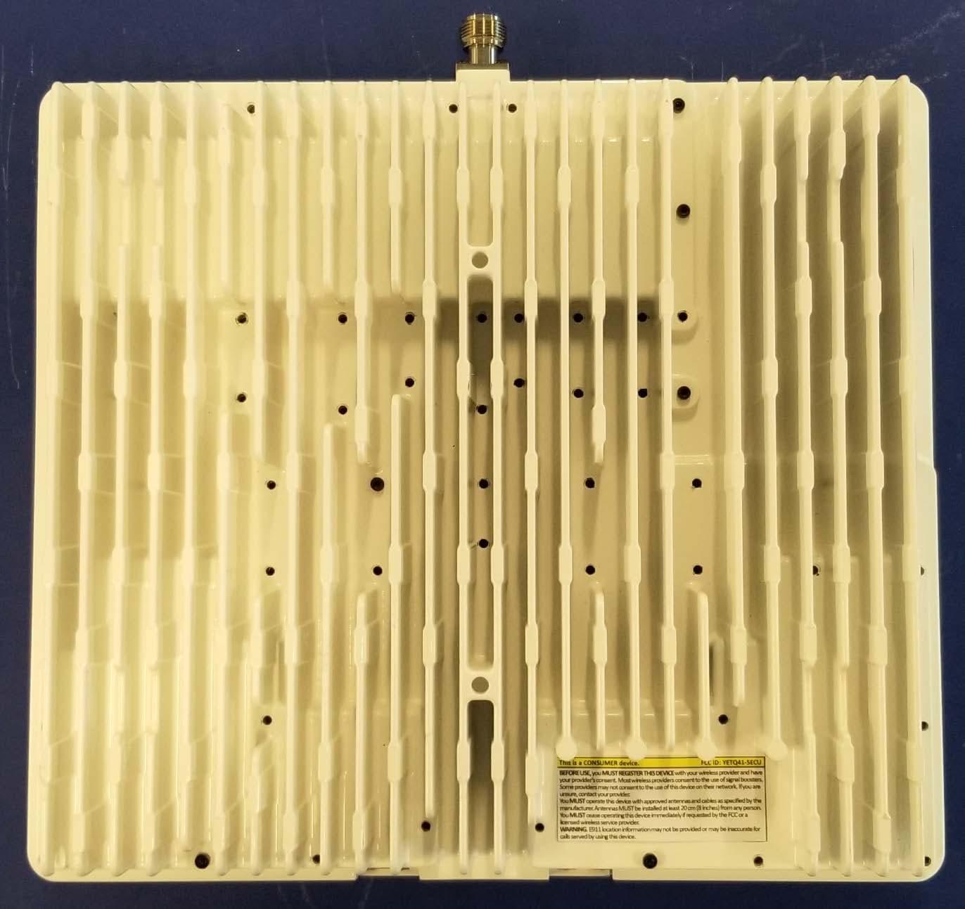
YETQ41-BXCU
May 05, 2023Provider-Specific Consumer Signal Booster
Equipment Class
B2P - Part 20 Provider-Specific Consumer Booster (CMRS)
YETQ44-1M34CNU
Feb 14, 2023Provider-Specific Consumer Signal Booster
Equipment Class
B2P - Part 20 Provider-Specific Consumer Booster (CMRS)