YEY-VISAGE1-2010Visage VDU System
GPS Industries, LLC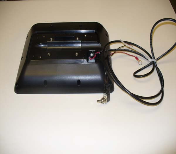
Click to zoom
Application Details
- Equipment Class
- DTS - Digital Transmission System
- Date of Grant
- Jun 02, 2010
- Application Purpose
- Original Equipment
- Date of Application
- May 31, 2010
- Equipment Note
- Visage VDU System
- Frequency Range
- 2412.00000000 - 2462.00000000
- Company
- GPS Industries, LLC
- Country
- United States
Documents & Files
Document Text
Text extracted from the exhibit documents filed with the FCC. Open a document above to read the original.
Users Manual
VDU User Manual 1074 North Orange Avenue Sarasota, Florida, 34236 1 888 575 2901 www.gpsindustries.com !"!#$% &'(()*+&$,+'*- &'((+--+'* +*,!# !#!*&! -,$,!(!*, !"# $%&"'($)* !+# ,$$) *$#*$- +)- ./&)- */ 0/('12 3"*! *!$ 1"("*# ./4 51+## 6 -"7"*+1 -$8"0$9 '&4#&+)* */ :+4* ;< /. *!$ =55 4&1$#> !$#$ 1"("*# +4$ -$#"7)$- */ '4/8"-$ 4$+#/)+,1$ '4/*$0*"/) +7+")#* !+4(.&1 ")*$4.$4$)0$ ") + 4$#"-$)*"+1 ")#*+11+*"/)> !"# $%&"'($)* 7$)$4+*$#9 &#$# +)- 0+) 4+-"+*$ 4+-"/ .4$%&$)02 $)$4729 +)- ". )/* ")#*+11$- +)- &#$- ") +00/4-+)0$ 3"*! *!$ ")#*4&0*"/)#9 (+2 0+&#$ !+4(.&1 ")*$4.$4$)0$ */ 4+-"/ 0/((&)"0+*"/)> ?/3$8$49 *!$4$ "# )/ 7&+4+)*$$ *!+* ")*$4.$4$)0$ 3"11 )/* /00&4 ") + '+4*"0&1+4 ")#*+11+*"/)> @. *!$ $%&"'($)* -/$# 0+&#$ !+4(.&1 ")*$4.$4$)0$ */ 4+-"/ /4 *$1$8"#"/) 4$0$'*"/)9 3!"0! 0+) ,$ -$*$4(")$- ,2 *&4)")7 *!$ $%&"'($)* /.. +)- /)9 *!$ &#$4 "# $)0/&4+7$- */ *42 */ 0/44$0* *!$ ")*$4.$4$)0$ ,2 /)$ /4 (/4$ /. *!$ ./11/3")7 ($+#&4$#A B C$/4"$)* /4 4$1/0+*$ *!$ 4$0$"8")7 +)*$))+> B @)04$+#$ *!$ #$'+4+*"/) ,$*3$$) *!$ $%&"'($)* +)- 4$0$"8$4> B 5/)#&1* *!$ -$+1$49 /4 +) +&*!/4"D$- *$0!)"0"+) ./4 !$1'> && &$),+'*. E)2 0!+)7$# /4 (/-"F0+*"/)# )/* $G'4$##12 +''4/8$- ,2 *!$ '+4*2 4$#'/)#",1$ ./4 0/('1"+)0$ 0/&1- 8/"- *!$ &#$4H# +&*!/4"*2 */ /'$4+*$ *!"# $%&"'($)*> Contents 2 Starting up the Visage VDU 3 The Golf Map Screen 3 8 The Main Menu 8 9 Scorecard 10 Leader Board 11 Send Message 12 Order Food 14 Site Map 16 Settings GPS Industries, LLC Visage VDU User Manual 1 Starting up the Visage VDU When you turn on a unit, it will first go through a series of diagnostics. The screen will show a “booting up” message and a progress indicator. The Welcome Screen After boot up is complete, the VDU will typically show a course’s “Welcome Screen.” The Welcome Screen is an ad the course defines welcoming golfers to the course that displays when golf cars are near the clubhouse or in the staging area. GPS Industries, LLC Visage VDU User Manual 2 The Golf Map Screen The main screen that golfers will interact with is the Golf Map screen. This screen shows a map of the current hole and yardages to hazards and other point of interest. Flyovers When golfers first reach a hole, they will see a a 3D flyover to help them plan their strategy for the hole. After the flyover finishes playing, the screen will return to the golf map. Golfers can view the flyover again at any time by pressing the “view flyover” button on the screen. GPS Industries, LLC Visage VDU User Manual 3 Distances The Visage VDU uses GPS to calculate distances to hazards and other points of interest on the golf course. The distances are measured by line-of-sight (or “as the crow flies”), and may differ from yardages given on your course’s scorecard. Scorecard distances are typically measured by line-of-play, and so may be larger than the line-of-sight distance. Yards to Pin / Center of Green In the upper corner of the screen, there is a large box that shows the yardage to the pin if the course has defined a pin placement for that hole. If no pin placement is defined, the box will show the yardage to the center of the green, and the Pin icon will be replaced with a Center of Green icon. GPS Industries, LLC Visage VDU User Manual 4 Navigation Panel In the bottom corner of the screen, there is a navigation panel that allows golfers to access the main menu, view flyovers, and zoom in or out on the hole. If an insert ad is defined for the hole, it will display in this spot. If no ad is defined, the navigation panel will move the bottom of the screen. Ads During play, ads are shown in the corner of the screen. When you approach the green, you may see a full-screen ad. To dismiss this ad, touch the screen anywhere. Your car icon Your position is shown on the screen with an icon of a golf car. Note that other golf cars’ positions are not shown. GPS Industries, LLC Visage VDU User Manual 5 Tee shot distances After you hit your drive and move away from the teebox, Visage will display distances measured from your golf car back to up to five teeboxes. This yardage can be used to help you determine the distance of your drive. This is shown in an informational popup that appears at the bottom of the screen. Car Ahead On blind tee shots, the Visage VDU may warn the golfer that someone is in the driving area. View the approach/hole When you begin play on a hole, Visage first shows a “hole view,” or a map of the entire hole. As you approach the green, Visage will automatically zoom in to a “green view.” The golfer can elect to zoom in to the green view or back out to the hole view at any time by pressing the Zoom button on the screen. GPS Industries, LLC Visage VDU User Manual 6 Select another hole To select another hole, first press the “Main Menu” button. Then, press the “Choose Hole” button. On the “Choose Hole” screen, touch the number of the hole you would like to play, then press “Play this Hole.” The Visage VDU will show a preview image of that hole. Hole conflict screen If you drive onto the teebox of another hole while playing your current hole, Visage may prompt you to ask whether you are still playing your current hole or if you would like to switch to the other one. Access the main menu To access the main menu, simply press the “Main Menu” button in the navigation panel. GPS Industries, LLC Visage VDU User Manual 7 The Main Menu The Visage Main Menu allows you access to features such as food ordering, scorecards and leaderboards, and messaging. To access the Main Menu, simply press the Main Menu button from any screen. Once on the Main Menu, you can select the feature you wish to use by pressing the appropriate button. Return to the Golf Map To return to the Golf Map screen, simply press the “Return to Golf” button. GPS Industries, LLC Visage VDU User Manual 8 Scorecard The Visage scorecard allows you to enter scores for up to four players. After you have finished playing a hole (by driving from the previous green to the next tee), Visage will automatically swit…
Text truncated - open the document above for the full version.
Cover Letter(s)
@GPSindusrries,., Authority to Act as Agent Date: May lI,20t0 AMERICAN TELECOMMUNICATION CERTIFICATION BODY INC. 6731 Whittier Avenue suite c110 Mcl-ean, VA22IOI Subject: Agent Authorization To whom it may concern: We GPS Industries LLC. , the undersigned, Hereby authorizes Professional Testing (EMD Inc. to act on its behalf in all matters relating to application for Equipment authorization, including the signing of all documents relating to these matters. All acts carried out by Professional Testing (EMI) Inc. on our behalf shall have the same effect as our own action. We, the undersigned, hereby certify that we are not subject to a denial of federal benefits, that includes FCC benefits, pursuant to Section 5301 of the Anti-Drug Abuse Act of 1988,21U.S.C. 853(a). This authorizationis valid until further written notice from the applicant. Dave Mullinix Vice President of Engineering GGP$indunrier".. 1074 North Orange Avenue Sarasota, Florida 34236 USA 1074 N. Orange Ave. Sarasota, Florida3/.2S6 gpsindrstries.com
External Photos
External Photos
Internal Photos
Internal Photos
RF Exposure Info
Project 10680-10 Prepared for: GPS Industries, LLC 1074 N. Orange Ave. Sarasota, FL 34236 By Professional Testing (EMI), Inc. 1601 N. A.W. Grimes Blvd., Suite B Round Rock, Texas 78665 May 26, 2010 MPE / RF Exposure Report Visage VDU YEY-VISAGE1-2010 10680-10 Page 2 of 5 Table of Contents Title Page ........................................................................................................................................1 Table of Contents ...........................................................................................................................2 Certificate of Compliance ..............................................................................................................4 1.0 MPE Prediction ...................................................................................................................4 1.1 Evaluation Procedure .......................................................................................................4 1.2 Evaluation Criteria ...........................................................................................................4 NOTICE: (1) This Report must not be used to claim product endorsement, by NVLAP, NIST, the FCC or any other Agency. This report also does not warrant certification by NVLAP or NIST. (2) This report shall not be reproduced except in full, without the written approval of Professional Testing (EMI), Inc. (3) The significance of this report is dependent on the representative character of the test sample submitted for evaluation and the results apply only in reference to the sample tested. The manufacturer must continuously implement the changes shown herein to attain and maintain the required degree of compliance. 10680-10 Page 3 of 5 Applicant: GPS Industries, LLC. Applicant’s Address: 1074 N. Orange Ave Sarasota, FL 34236 FCC ID: YEY-VISAGE1-2010 IC Number: 8998A-VISAGE12010 Project Number: 10680-10 Test Dates: April 13-14, 2010 and May 5,7, and 10, 2010 I, Jason Anderson, for Professional Testing (EMI), Inc., being familiar with the FCC rules and test procedures have reviewed the test setup, measured data and this report. I believe them to be true and accurate. Jason Anderson Director of Testing Services This report has been reviewed and accepted by GPS Industries, LLC. The undersigned is responsible for ensuring that this device will continue to comply with the FCC and IC rules. 10680-10 Page 4 of 5 1.0 MPE Prediction Prediction of MPE limit at a given distance was made by using equation from page 18 of OET Bulletin 65, Edition 97-01. In order to prove that SAR is not required we used the combined MPE calculation of the Wi-Fi device and the GPRS module. The data is contained in the worksheet below. 1.1 Evaluation Procedure S=PG/4ߨR² Where: S = power density P= power input to antenna G = power gain of the antenna in the direction of interest relative to an isotropic radiator R = distance to the center of radiation of the antenna 1.2 Evaluation Criteria MPE limit for uncontrolled exposure at prediction frequency (mW/cm²): 1.0 10680-10 Page 5 of 5 MPE Prediction Calculation PROJECT # DATE RULE DISTANCE ANTENNA RBW VBW DETECTOR 10680-10 May 10, 2010 15.247 N/A N/A N/A N/A N/A Calculations S=PG/4ߨR² Where: S = power density P= power input to antenna G = power gain of the antenna in the direction of interest relative to an isotropic radiator R = distance to the center of radiation of the antenna MPE Wi-Fi Transmitter Frequency (MHz) Peak Output Power (dBm) Peak Output Power (mW) Prediction Distance (cm) Max Antenna Gain (dBi) Max Antenna Gain (numeric) Power Density at 20.0 cm (mW/cm²) 2412 24.82 303.4 20 2.0 1.585 .09571 MPE GPRS Transmitter Frequency (MHz) Peak Output Power (dBm) Peak Output Power (mW) Prediction Distance (cm) Max Antenna Gain (dBi) Max Antenna Gain (numeric) Power Density at 20.0 cm (mW/cm²) 1900 30 974.99 20 3.0 3.0 .58190 NOTE: Antenna Gain is estimated worst case scenario. .09571 + .58190 = .67761 mW/cm² NOTE: Client provides professional installation instructions which detail how to maintain the 20 cm separation distance.
Test Report
Project 10680-10 Prepared for: GPS Industries, LLC 1074 N. Orange Ave. Sarasota, FL 34236 By Professional Testing (EMI), Inc. 1601 N. A.W. Grimes Blvd., Suite B Round Rock, Texas 78665 June 3, 2010 CERTIFICATION Wireless Test Report Visage VDU YEY-VISAGE1-2010 10680-10 Page 2 of 40 Table of Contents Title Page ........................................................................................................................................1 Table of Contents ...........................................................................................................................2 Certificate of Compliance ..............................................................................................................4 1.0 Introduction .........................................................................................................................5 1.1 Scope ................................................................................................................................5 1.2 EUT Description ..............................................................................................................5 1.3 EUT Operation .................................................................................................................5 1.4 Test Site ...........................................................................................................................5 1.5 Applicable Documents .....................................................................................................6 2.0 Power Line Conducted Emissions .....................................................................................7 3.0 Peak Output Power .............................................................................................................7 3.1 Test Procedure .................................................................................................................7 3.2 Test Criteria .....................................................................................................................7 4.0 Occupied Bandwidth ..........................................................................................................8 4.1 Test Procedure .................................................................................................................8 4.2 Test Criteria .....................................................................................................................8 5.0 Power Spectral Density .......................................................................................................8 5.1 Test Procedure .................................................................................................................8 5.2 Test Criteria .....................................................................................................................8 6.0 Band Edge Spurious Emissions .........................................................................................9 6.1 Test Procedure .................................................................................................................9 6.2 Test Criteria .....................................................................................................................9 7.0 Out of Band Spurious Emissions .......................................................................................9 7.1 Test Procedure .................................................................................................................9 7.2 Test Criteria ...................................................................................................................10 8.0 Antenna Requirements .....................................................................................................10 8.1 Evaluation Procedure .....................................................................................................10 8.2 Evaluation Criteria .........................................................................................................10 9.0 Modifications .....................................................................................................................10 10.0 Test Equipment .................................................................................................................10 Appendix A Test Setup Diagrams ..........................................................................................12 Appendix B Test Results .........................................................................................................15 10680-10 Page 3 of 40 NOTICE: (1) This Report must not be used to claim product endorsement, by NVLAP, NIST, the FCC or any other Agency. This report also does not warrant certification by NVLAP or NIST. (2) This report shall not be reproduced except in full, without the written approval of Professional Testing (EMI), Inc. (3) The significance of this report is dependent on the representative character of the test sample submitted for evaluation and the results apply only in reference to the sample tested. The manufacturer must continuously implement the changes shown herein to attain and maintain the required degree of compliance. 10680-10 Page 4 of 40 Applicant: GPS Industries, LLC. Applicant’s Address: 1074 N. Orange Ave Sarasota, FL 34236 FCC ID: YEY-VISAGE1-2010 IC Number: 8998A-VISAGE1-2010 Project Number: 10680-10 Test Dates: April 13-14, 2010 and May 5,7, and 10, 2010 The GPS Industries, Visage VDU was tested to and found to be in compliance with FCC 47 CFR Part 15 and IC RSS-210 issue 7. NOTE: Pre scans of EUT determined that the operating voltage (12 VDC or 48 VDC) did not affect performance. The highest emissions generated by the above equipment are listed below: Parameter Frequency (MHz) Level Limit Margin (dB) Transmitter: Mains Conducted Not applicable, battery powered. Transmitter: Radiated Spurious 155.982 38.8 dBμV/m @ 3 m 40 dBμV/m -1.2 Transmitter: Peak Power @ 3 m 2412 24.82…
Text truncated - open the document above for the full version.
Test Setup Photos
Test Setup Photos 12 VDC 48 VDC
Contact Information
Applicant
Bruce Tenerowicz(Director, Electrical Core Modules & Technology)
Technical Contact
Professional Testing Inc.Jason Anderson
[email protected]512 244 3371
1601 FM 1460 Suite B · Round Rock, Texas · United States
Test Firm
Professional Testing (EMI), Inc.Robert McCollough
Technical Specifications
| # | Rule Parts | Frequency Range | Power Output |
|---|---|---|---|
| 1 | 15C | 2.41 GHz - 2.46 GHz | 303.40 mW |
Other Applications from GPS Industries, LLC
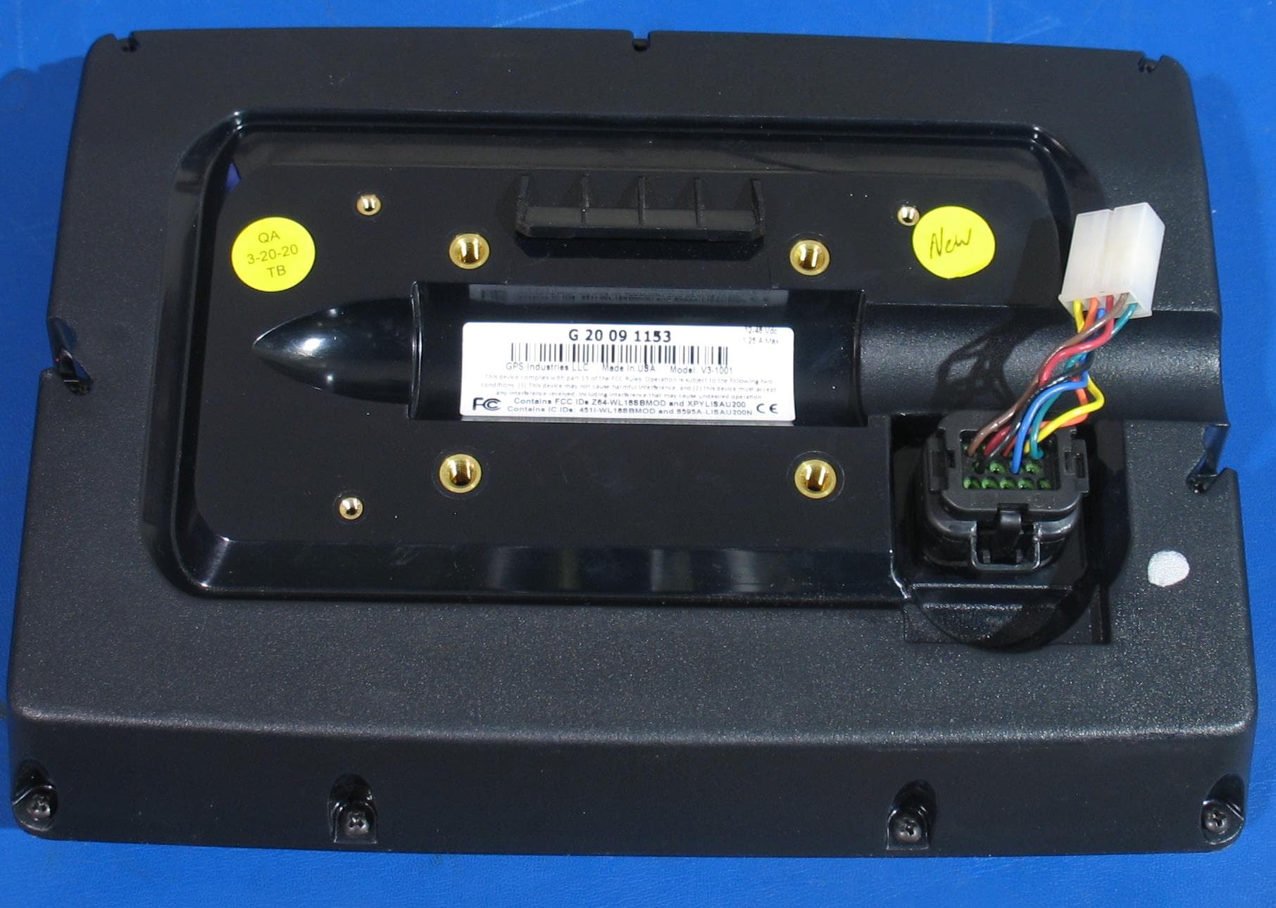
YEY-V3-1005A
Mar 09, 2021Visage Touchscreen Display
Equipment Class
DXX - Part 15 Low Power Communication Device Transmitter