YFJANT100824HAntenna / Base Station
Riedel Communications GmbH&Co KG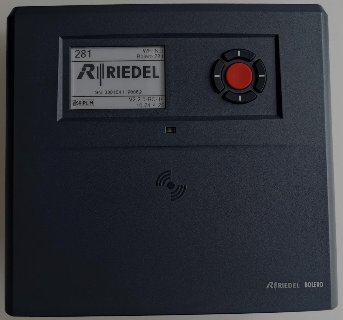
Click to zoom
Application Details
- Equipment Class
- DXX - Part 15 Low Power Communication Device Transmitter
- Date of Grant
- Jul 08, 2024
- Application Purpose
- Original Equipment
- Date of Application
- Jul 08, 2024
- Equipment Note
- Antenna / Base Station
- Frequency Range
- 13.56000000 - 13.56000000
- Country
- Germany
Documents & Files
Document Text
Text extracted from the exhibit documents filed with the FCC. Open a document above to read the original.
Users Manual
User Manual 03-000HB01EG-F10 Bolero 3.1 Next Generation Wireless 03-000HB01EG-F10 Bolero 3.1 User Manual © December 2022 Riedel Communications GmbH & Co. KG. ALL RIGHTS RESERVED. UNDER THE COPYRIGHT LAWS, THIS MANUAL MAY NOT BE COPIED, IN WHOLE OR IN PART, WITHOUT THE WRITTEN CONSENT OF RIEDEL. EVERY EFFORT HAS BEEN MADE TO ENSURE THAT THE INFORMATION IN THIS MANUAL IS ACCURATE. RIEDEL IS NOT RESPONSIBLE FOR PRINTING OR CLERICAL ERRORS. ALL TRADEMARKS ARE THE PROPERTY OF THEIR RESPECTIVE OWNERS. This device complies with Part 15 of the FCC Rules and with Industry Canada licence-exempt RSS standard(s). Operation is subject to the following two conditions: (1) this device may not cause harmful interference, and (2) this device must accept any interference received, including interference that may cause undesired operation. Le présent appareil est conforme aux CNR d'Industrie Canada applicables aux appareils radio exempts de licence. L'exploitation est autorisée aux deux conditions suivantes: (1) l'appareil ne doit pas produire de brouillage, et (2) l'utilisateur de l'appareil doit accepter tout brouillage radioélectrique subi, même si le brouillage est susceptible d'en compromettre le fonctionnement. This equipment has been tested and found to comply with the limits for a Class A digital device, pursuant to Part 15 of the FCC Rules. These limits are designed to provide reasonable protection against harmful interference when the equipment is operated in a commercial environment. This equipment generates, uses, and can radiate radio frequency energy and, if not installed and used in accordance with the instruction manual, may cause harmful interference to radio communications. Operation of this equipment in a residential area is likely to cause harmful interference in which case the user will be required to correct the interference at his own expense. Changes or modifications made to this equipment not expressly approved by Riedel may void the FCC authorization to operate this equipment. Radiofrequency radiation exposure Information (for the Beltpack): For body worn operation, this equipment has been tested and meets the FCC RF exposure guidelines when used with the Riedel accessories supplied or designated for this product. Use of other accessories may not ensure compliance with FCC RF exposure guidelines. Radiofrequency radiation exposure Information (for the Antenna): This equipment complies with FCC and IC radiation exposure limits set forth for an uncontrolled environment. This equipment should be installed and operated with minimum distance of 20 cm between the radiator and your body. This transmitter must not be co-located or operating in conjunction with any other antenna or transmitter. Cet équipement est conforme aux limites d'exposition aux rayonnements IC établies pour un environnement non contrôlé. Cet équipement doit être installé et utilisé avec un minimum de 20 cm de distance entre la source de rayonnement et votre corps. Ce transmetteur ne doit pas etre place au meme endroit ou utilise simultanement avec un autre transmetteur ou antenne. This device is granted pursuant to the Japanese Radio Law ( ) and the Japanese Telecommunications Business Law ( ). This device should not be modified (otherwise the granted designation number will become invalid). Beltpack: Este produto está homologado pela Anatel, de acordo com os procedimentos regulamentados pela Resolução n°. 242/2000 e atende aos requisitos técnicos aplicados, incluindo os limites de exposição da Taxa de Absorção Específica referente a campos elétricos, magnéticos e eletromagnéticos de radiofreqüência de acordo com as Resoluções n°. 303/2002 e 533/2009. Taiwan NCC Warning Statement (930322) The device conforms to the following EU guidelines as attested by the CE mark. EMV (EMC) 2014/30/EU NSR (LVD) 2014/35/EU RTTE (RED) 2014/53/EU YFJANT101019 (Bolero DECT Antenna / BL-ANT-1010-19) YFJBPK100619 (Bolero DECT Beltpack / BL-BPK-1006-19) YFJANT100824 (Bolero 2.4GHz Antenna / BL-ANT-1008-24) YFJBPK100624 (Bolero 2.4GHz Beltpack / BL-BPK-1006-24) YFJBPK100424 (Bolero 2.4GHz Beltpack / BL-BPK-1004-24) StandardsEN 300 328 V1.9.1 / ETSI EN 300 328 V2.0.20 EN 300 330 V1.8.1 / ETSI EN 300 330 V2.1.0 EN 301 406 V2.2.1 EN 301 489-1/-3/-6/-17, EN 55022, EN 55024 IEC/EN 60950-1, IEC 62368-1 ARIB STD-T66 ARIB STD-T101 Industry Canada 8706A-ANT101019 (Bolero DECT Antenna / BL-ANT-1010-19) 8706A-BPK100619 (Bolero DECT Beltpack / BL-BPK-1006-19) 8706A-ANT100824 (Bolero 2.4GHz Antenna / BL-ANT-1008-24) 8706A-BPK100624 (Bolero 2.4GHz Beltpack / BL-BPK-1006-24) 8706A-BPK100424 (Bolero 2.4GHz Beltpack / BL-BPK-1004-24) Australia Any device that connects to the data ports must comply with the clause 4.7 of AS/NZS 60950.1 Warning: This equipment is compliant with Class A of CISPR 32. In a residential environment this equipment may cause radio interference. Singapore Complies with IMDA Standards DB105184 Taiwan Complies with BSMI Standards Bolero 3.1 User Manual CONTENT 1 Preface 7 Information........................................................................................................................................................ 81.1 Change History................................................................................................................................................ 111.2 Package Version.............................................................................................................................................. 141.3 About Bolero.................................................................................................................................................... 151.4 2 Features in Detail 17 System Modes................................................................................................................................................. 172.1 2.1.1Standalone/AES67 (2110) ....................................................................................................…
Text truncated - open the document above for the full version.
Users Manual
100 Bolero 3.1 User Manual The function is triggered depending on the view where it is configured. Functions in the view... Always-On are permanently activated. Trigger are switched by a trigger. On-Talk are automatically activated if it is talked in the respective channel. On-Notification/Beep are automatically activated if the respective channel receives a notification/beep. On-Vox are activated when and as long as the VOX is triggered. (The parameters for VOX activation are configurable on the page 'General'.)Figure 117: edit audio channel – Trigger The page Beltpacks allows programming the Beltpacks key functions individually. Click the button to configure the respective Beltpack. Use the Profiles page to configure all Beltpacks assigned to the profile in one step. (Profiles (User Rights)) Figure 118: Registered Beltpacks In the Keys section the keys of the Beltpack can be configured and functions can be assigned. Figure 119: edit Beltpacks – Keys After this configuration the Beltpacks are able to communicate to other Beltpacks as well as to the audio channels of the IO devices. 101 Bolero 3.1 User Manual 2.5Add Devices To add more Antennas to a working Network Space, the new Antennas must not be assigned to any other Net. If a new Antenna is already assigned to a Net, see chapter 'Remove Devices > Antennas' to remove it from the current Net before proceeding the registration. New Antennas have disabled radio, if the Antenna is not known by the matrix. Connect the Antenna's 'AES67/Config' port to the network switch. If a PoE+ switch is used, the Antenna is also supplied with power. Alternatively, attach a separate DC power supply to the Antenna's power connector. The IP address of the Antenna is shown in the bottom right of the display (e.g. 192.168.41.151). Figure 120: Antenna Display Open the web interface of the Antenna to access the configuration: Enter the IP address of a Bolero Antenna in the Web- Browser (e.g. 192.168.41.151). Figure 121: Web interface of the Antenna Take care that the Antennas IP address is in the same IP range as the existing Net. The IP settings can be modified in the web interface () as well as in the Antennas' menu (IP Settings). Select the unassigned Antenna(s) to be added to an existing Network Space. Selected elements will be highlighted. Figure 122: Selected new Antennas Click on the plus symbol off the unassigned Antenna(s) and select the entry 'Add Selected Antennas to Network Space...'. A dialog is opened to select the Net. Figure 123: Add to Network Space 102 Bolero 3.1 User Manual Select in the drop-down menu an existing Network Space. Click the Apply button. Figure 124: Dialog – Select Network Space This example shows the new added Antenna in the existing Network Space Bolero-Net. Figure 125: Added new Antenna in the Bolero-Net Do not forget to assign a unique User ID and a name to the new Antenna. Click the Edit icon of the new Antenna. Click the Apply button. Figure 126: Apply unique User ID In this example the Network Space consists now of two Antennas. Figure 127: Devices in the Bolero-Net 103 Bolero 3.1 User Manual 2.6Remove Devices In the Web Interface it is possible to remove registered Antennas as well as registered Beltpacks from a Net. 2.6.1Antennas To de-register Antennas from a Net, choose the register 'Antennas'. Then select the desired Antennas. Figure 128: Web Interface – Antennas Click on the plus symbol and select the item 'Remove Selected Antennas'. Figure 129: Remove Selected Antennas Confirm the opened dialog by clicking 'Ok'. Figure 130: Confirmation dialog The Antennas will be removed immediately from the Net. 104 Bolero 3.1 User Manual 2.6.2Beltpacks To de-register Beltpacks from a Net, choose the register 'Beltpacks'. Then select the desired Beltpacks. Figure 131: Web Interface – Registered Beltpacks Click on the plus symbol and select the menu item 'Deregister'. Figure 132: Deregister Confirm the opened dialog by clicking 'Ok'. Figure 133: Confirmation dialog The Beltpacks will be removed immediately from the Net. 105 Bolero 3.1 User Manual 2.7Firmware Update Upgrading From Earlier Versions The Network Space configuration and the Antenna configuration is preserved when updating from version 1.0.x/1.1.x/1.2.x/2.0.x. Configurations saved with version 1.0.x/1.1.x/1.2.x/2.0.x can be loaded in version 2.1.1. As final step of the update, all devices are rebooted. Please refresh your browser tab when the connection is re-established to conclude the update. Updating From Version 1.x.x If you plan to use Standalone/Link mode with Link-Power, you should update the system from version 1.x.x while the antennas are powered via XLR. Before an antenna can be powered via Link-Power or deliver power over the links after an update, it must be powered by XLR for at least a couple of minutes (to complete the update of the remote power controller firmware). Updating From Version 1.0.x Bolero Antennas running version 1.0.x have to be updated twice to this version. After a successful update you will see the package version 2.1.1 in the "Current Firmware" column of the Firmware Manager. Downgrading From This Version When downgrading to a previous version, the Network Space, Antenna configurations, and the IP address settings will be lost. Note that the Network Space name may be empty and the admin pin may be set to "1234" after a downgrade to version 1.0.x/1.1.x. Saved configurations of this version cannot be loaded on previous versions. This chapter describes the update procedure of Bolero Antennas. Depending on the system mode, following devices are required: Standalone AES67 Mode Standalone Link Mode Integrated Artist Mode PC Bolero firmware package (for example "bolero_v1.2.3-456.package") Network Switch (optionally with PoE+ functionality) Bolero-Antennas Standalone/AES67 Mode & Integrated/Artist Mode: Attach the PC to the network switch. Attach the 'AES67/Config' connector of the Bolero- Antennas to the network switch. If the Antennas are…
Text truncated - open the document above for the full version.
Attestation Statements
Riedel Communications 20.06.2024 1 / 1 Riedel Communications GmbH & Co. KG Uellendahler Strasse 353 42109 Wuppertal Germany Federal Communication Commission Authorization and Evaluation Division 7435 Oakland Mills Road Columbia, MD 21046 USA 20.06.2024 Attestation Statement according to 2.911(d)(5)(i) and 2.911(d)(5)(ii) FCC ID: YFJANT100824H TO WHOM IT MAY CONCERN: Hereby we certify that the equipment for which authorization is sought is not “covered” equipment prohibited from receiving an equipment authorization pursuant to section 2.903 of the FCC rules. Further we certify that, as of the date of the filing of the application, Riedel Communications is not identified on the Covered List as an entity producing “covered” equipment. Sincerely, Frank Eischet, CFO _____________ (signature & company stamp) Riedel Communications FCC Registration Number: 0019166321 Uellendahler Str. 353, 42109, Wuppertal, Germany Frank Eischet Tel: + 49 (0) 202 292 – 90 Email: [email protected]
Attestation Statements
^frrll RTEDEL Federal Communication Commission Authorization and Evaluation Division 7435 Oakland Mills Road Columbia, MD 21046 USA 26th of April2024 Attestation Statement according to 2.91 1 (dX7) TO WHOM IT MAY CONCERN: \A/e, Riedel Communications GmbH&Co KG designate Riedel Communications, lnc., to act as U.S. agent for service of process. Riedel Communications, lnc. with FCC Registration Number (FRN) 003534t1515 hereby acknowledges the obligation of the U.S. agent for service of process. Further Riedel Communications GmbH&Co KG accepts to maintain an agent for no less than one year after the grantee has terminated all marketing and importation or the conclusion of any Com m ission-related proceeding involving the equipment. Sincerely Qr* Ee*. (signature & company stamp) @$-aur" &co pany stamp) Riedel Communications GmbH&Co KG FRN:0019166321 Uellendahler Strasse 353, 42109 Wuppertal, Germany Jake Dodson +4924:2 292-0 , i Riedel Communications, lnc. FRN:0035348515 257OZA Rye Canyon Road, Santa Claritia, California, CA 91355, United Stat* Joyce Bente +1 818.559.6905 iovce. befrte@riedel. net
Cover Letter(s)
Name/Telefon Datum Wolfgang Fritz +49 202 292 90 Wuppertal, June 26, 2024 Declaration of Identity Re: Bolero BL-ANT-1008-24B The manufacturer Riedel Communications GmbH & Co.KG, located at Uellendahler Str. 353-Wuppertal- Germany, DE 814906984 as being the manufacturer of product Bolero Wireless Base Station, model BL-ANT- 1008-24, hereby declares that the product BL-ANT-1008-24B with HVIN BL-ANT-1008-24B-H is in all relevant Radio- and Terminal approval parameters for RFID (according to the FCC - Title 47 CFR Part 15 and RSS-210, Issue 10) identical to the product BL-ANT-1008-24B certified under: FCC ID: YFJANT100824 ISED certification number: 8706A-ANT100824 Furthermore, the current RFID reports can also be used for approval under new IDs due to the identical design. Regards, _________________ Signature of the responsible (of manufacturer) Wolfgang Fritz Senior Product Manager, Wireless Intercom Company Riedel Communications GmbH & Co KG Name Wolfgang Fritz Phone +49 202 292 90 Email [email protected] Datum June 26, 2024 To Cetecom Advanced GmbH Untertuerkheimer Str. 6-10 66117 Saarbruecken | Germany
Cover Letter(s)
LONG TERM CONFIDENTIALITY REQUEST for Certification Service in USA Federal Communication Commission Equipment Authorization Division, Application Processing Branch 7435 Oakland Mills Road Columbia, MD 21048 30th of April 2024 TO WHOM IT MAY CONCERN Pursuant to Paragraphs §0.457 and 0.459 of the Commission’s Rules (47 C.F.R.) and Section §552(b)(4) of the Freedom of Information Act, we request confidentiality for the following products: FCC ID Model name YFJBPK100624H BL-BPK-1006-24 YFJANT100824H BL-ANT-1008-24B For the product stated above, we request permanent confidentiality for exhibits which contain Operational Description, Block Diagram, Schematics, Parts Lists or Tune Up Information. The above exhibits contain our trade secrets and proprietary information that could be of benefit to our competitors. If you have any questions, please feel free to contact me at the address shown below. Sincerely, Name: Wolfgang Fritz Company: RIEDEL Communications GmbH & Co. KG Address: Uellendahler Str. 353, 42109 Wuppertal, Germany Phone: +49 202 292 – 0 Fax: +49 202 292 - 9799 Email: [email protected]
External Photos
Bolero BL-ANT-1008-24B DI Wolfgang Fritz 25 May 2021 1/5 External Photos Model: Bolero BL-ANT-1008-24B Bolero BL-ANT-1008-24B DI Wolfgang Fritz 25 May 2021 2/5 Bolero BL-ANT-1008-24B DI Wolfgang Fritz 25 May 2021 3/5 Bolero BL-ANT-1008-24B DI Wolfgang Fritz 25 May 2021 4/5 Bolero BL-ANT-1008-24B DI Wolfgang Fritz 25 May 2021 5/5
External Photos
Annex A101 - Photographs No.1-7493/24-01-01_TR1-A101-R1 April 30, 2024 DescriptionExternal photographs of EUT This document is electronically signed and valid without handwritten signature. Public keys for verification of the electronic signatures can be requested at the testing laboratory. Authorized Marco Bertolino Supervisor Radio Services Radio Labs cetecom advanced GmbH Untertürkheimer Str. 6-10, 66117 Saarbrücken Document No. 1-7493/24-01-01_TR1-A101-R1 Release 1 - Page 1 of 5 Photo 1 Photo 2 cetecom advanced GmbH Untertürkheimer Str. 6-10, 66117 Saarbrücken Document No. 1-7493/24-01-01_TR1-A101-R1 Release 1 - Page 2 of 5 Photo 3 Photo 4 cetecom advanced GmbH Untertürkheimer Str. 6-10, 66117 Saarbrücken Document No. 1-7493/24-01-01_TR1-A101-R1 Release 1 - Page 3 of 5 Photo 5 Photo 6 cetecom advanced GmbH Untertürkheimer Str. 6-10, 66117 Saarbrücken Document No. 1-7493/24-01-01_TR1-A101-R1 Release 1 - Page 4 of 5 Photo 7 - END OF DOCUMENT - cetecom advanced GmbH Untertürkheimer Str. 6-10, 66117 Saarbrücken Document No. 1-7493/24-01-01_TR1-A101-R1 Release 1 - Page 5 of 5
ID Label/Location Info
Labels for Riedel Bolero BL-ANT-1008-24B Example: Location: The label is placed on the backside of the front lip of the housing. See red marked area in the photos.
Internal Photos
Bolero BL-ANT-1008-24B Michael Fischer 25. April 2024 1/4 Internal Photos Model: Bolero BL-ANT-1008-24B Bolero BL-ANT-1008-24B Michael Fischer 25. April 2024 2/4 Bolero BL-ANT-1008-24B Michael Fischer 25. April 2024 3/4 Bolero BL-ANT-1008-24B Michael Fischer 25. April 2024 4/4
RF Exposure Info
© cetecom advanced GmbH Page 1 of 12 TEST REPORT Test report no.: 1-7493-24-01-04_TR1-R02 Testing laboratory Applicant cetecom advanced GmbH Untertuerkheimer Strasse 6 – 10 66117 Saarbruecken / Germany Phone: + 49 681 5 98 - 0 Fax: + 49 681 5 98 - 9075 Internet: https://cetecomadvanced.com e-mail: [email protected] Accredited Testing Laboratory: The testing laboratory (area of testing) is accredited according to DIN EN ISO/IEC 17025 (2018-03) by the Deutsche Akkreditierungsstelle GmbH (DAkkS). The accreditation is valid for the scope of testing procedures as stated in the accreditation certificate with the registration number: D-PL-12047-01-00. ISED Testing Laboratory Recognized Listing Number: DE0001 FCC designation number: DE0002 Riedel Communications GmbH & Co. KG Uellendahler Strasse 353 42109 Wuppertal / GERMANY Contact: Wolfgang Fritz e-mail: [email protected] Manufacturer Riedel Communications GmbH & Co. KG Uellendahler Strasse 353 42109 Wuppertal / GERMANY Test Item Kind of test item: Antenna / Base Station Model name: BL-ANT-1008-24B FCC ID: YFJANT100824H Frequency: 2402-2483 MHz Technology tested: Proprietary This test report is electronically signed and valid without handwritten signature. For verification of the electronic signatures, the public keys can be requested at the testing laboratory. Test report authorized: Test performed: Alexander Hnatovskiy Eric Tuettmann Lab Manager Testing Manager Radio Labs Radio Labs Test report no.: 1-7493-24-01-04_TR1-R02 © cetecom advanced GmbH Page 2 of 12 1 Table of contents 1 Table of contents ............................................................................................................................................. 2 2 General Information ......................................................................................................................................... 3 2.1 Notes and Disclaimer ............................................................................................................................ 3 2.2 References ............................................................................................................................................ 3 2.3 Structure of this Document ................................................................................................................... 3 3 General RF Exposure Test Exemptions ............................................................................................................ 4 3.1 1 mW Test Exemption ........................................................................................................................... 5 3.2 MPE-Based Test Exemption ................................................................................................................. 5 3.3 SAR-Based Test Exemption .................................................................................................................. 5 3.4 Simultaneous Transmission ............................................................................................................... 6 4 1 mW Test Exemption ...................................................................................................................................... 7 4.1 Detailed Description .............................................................................................................................. 7 4.2 Results ................................................................................................................................................... 7 5 MPE-Based Test Exemption ............................................................................................................................ 8 5.1 Detailed Description .............................................................................................................................. 8 5.2 Results ................................................................................................................................................... 8 6 SAR-Based Test Exemption ............................................................................................................................. 9 6.1 Detailed Description .............................................................................................................................. 9 6.2 Results ................................................................................................................................................. 10 7 Simultaneous Transmission .......................................................................................................................... 11 7.1 Detailed Description ............................................................................................................................ 11 7.2 Result................................................................................................................................................... 11 8 Conclusion ...................................................................................................................................................... 12 Document History: ....................................................................................................................................... 12 Test report no.: 1-7493-24-01-04_TR1-R02 © cetecom advanced GmbH Page 3 of 12 2 General Information 2.1 Notes and Disclaimer The test results of this test report relate exclusively to the test item specified in this test report. cetecom advanced GmbH does not assume responsibility for any conclusions and generalizations drawn from the test results with regard to other specimens or samples of the type of the equipment represented by the test item. The test report may only be reproduced or published in full. Reproduction or publication of extracts from the report requires the prior written approval of cetecom advanced GmbH. The testing service provided by cetecom advanced GmbH has been rendered under t…
Text truncated - open the document above for the full version.
Test Report
TEST REPORT Test report no.: 1-7493-24-01-07_TR1-R02 Testing laboratory Applicant cetecom advanced GmbH Untertuerkheimer Strasse 6 – 10 66117 Saarbruecken / Germany Phone: + 49 681 5 98 - 0 Fax: + 49 681 5 98 - 9075 Internet: https://cetecomadvanced.com e-mail: [email protected] Accredited Testing Laboratory: The testing laboratory (area of testing) is accredited according to DIN EN ISO/IEC 17025 (2018-03) by the Deutsche Akkreditierungsstelle GmbH (DAkkS). The accreditation is valid for the scope of testing procedures as stated in the accreditation certificate with the registration number: D-PL-12047-01-00. ISED Testing Laboratory Recognized Listing Number: DE0001 FCC designation number: DE0002 Riedel Communications GmbH & Co. KG Uellendahler Strasse 353 42109 Wuppertal / GERMANY Phone: -/- Contact: Wolfgang Fritz e-mail: [email protected] Manufacturer Riedel Communications GmbH & Co. KG Uellendahler Strasse 353 42109 Wuppertal / GERMANY Test standard/s FCC - Title 47 CFR Part 15 FCC - Title 47 of the Code of Federal Regulations; Chapter I; Part 15 - Radio frequency devices RSS - 210 Issue 10 Spectrum Management and Telecommunications Radio Standards Specification - Licence-Exempt Radio Apparatus: Category I Equipment For further applied test standards please refer to section 3 of this test report. Test Item Kind of test item: Antenne / Base Station Model name: BL-ANT-1008-24B FCC ID: YFJANT100824H IC: 8706A-ANT100824H Frequency: 13.56 MHz Technology tested: RFID Antenna: Integrated antenna Power supply: 48V DC by PoE or 10V to 57V DC by power supply unit Temperature range: -10°C to +45°C This test report is electronically signed and valid without handwritten signature. For verification of the electronic signatures, the public keys can be requested at the testing laboratory. Test report authorized: Test performed: On behalf of Christoph Schneider Tobias Wittenmeier Lab Manager Testing Manager Radio Communications Radio Communications Test report no.: 1-7493-24-01-07_TR1-R02 © cetecom advanced GmbH Page 2 of 30 1 Table of contents 1 Table of contents ............................................................................................................................................. 2 2 General information ......................................................................................................................................... 3 2.1 Notes and disclaimer ............................................................................................................................ 3 2.2 Application details ................................................................................................................................ 3 2.3 Test laboratories sub-contracted ......................................................................................................... 3 3 Test standard/s, references and accreditations.............................................................................................. 4 4 Reporting statements of conformity – decision rule ....................................................................................... 5 5 Test environment ............................................................................................................................................. 6 6 Test item .......................................................................................................................................................... 6 6.1 General description ............................................................................................................................... 6 6.2 Additional information .......................................................................................................................... 6 7 Description of the test setup ............................................................................................................................ 7 7.1 Shielded semi anechoic chamber ......................................................................................................... 8 7.2 Shielded fully anechoic chamber ........................................................................................................ 10 7.3 AC conducted ...................................................................................................................................... 11 7.4 RF measurements normal and extreme conditions ............................................................................ 12 8 Sequence of testing ....................................................................................................................................... 13 8.1 Sequence of testing radiated spurious 9 kHz to 30 MHz ................................................................... 13 8.2 Sequence of testing radiated spurious 30 MHz to 1 GHz .................................................................. 14 9 Measurement uncertainty .............................................................................................................................. 15 10 Summary of measurement results ............................................................................................................. 16 11 Additional comments ................................................................................................................................. 16 12 Measurement results ................................................................................................................................. 17 12.1 Occupied bandwidth ........................................................................................................................ 17 12.2 Field strength of the fundamental ......................................................…
Text truncated - open the document above for the full version.
Contact Information
Applicant
Ralf Henke
Test Firm
cetecom advanced GmbHGerald Schmidt
Technical Specifications
| # | Rule Parts | Frequency Range | Power Output |
|---|---|---|---|
| 1 | 15C | 13.56 MHz - 13.56 MHz | - |
Other Applications from Riedel Communications GmbH&Co KG
YFJDSP1216HL
Jan 20, 20261200 Series desktop SmartPanel with 16 hybrid lever keys
Equipment Class
DSS - Part 15 Spread Spectrum Transmitter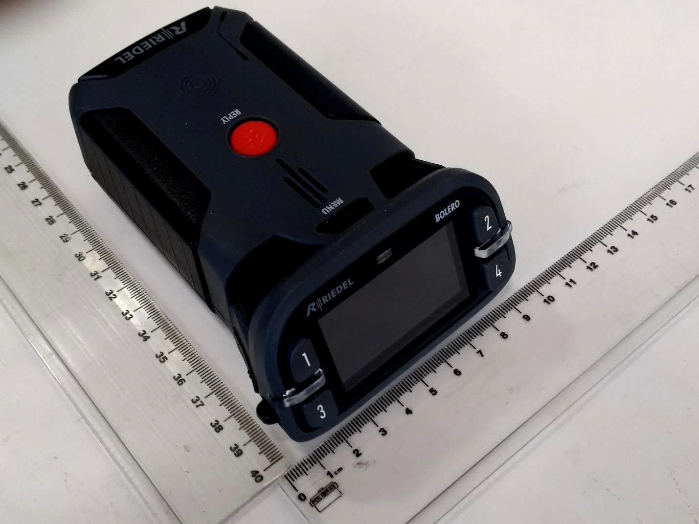
YFJBPK100624H
Jul 08, 2024Beltpack Standard
Equipment Class
DXX - Part 15 Low Power Communication Device Transmitter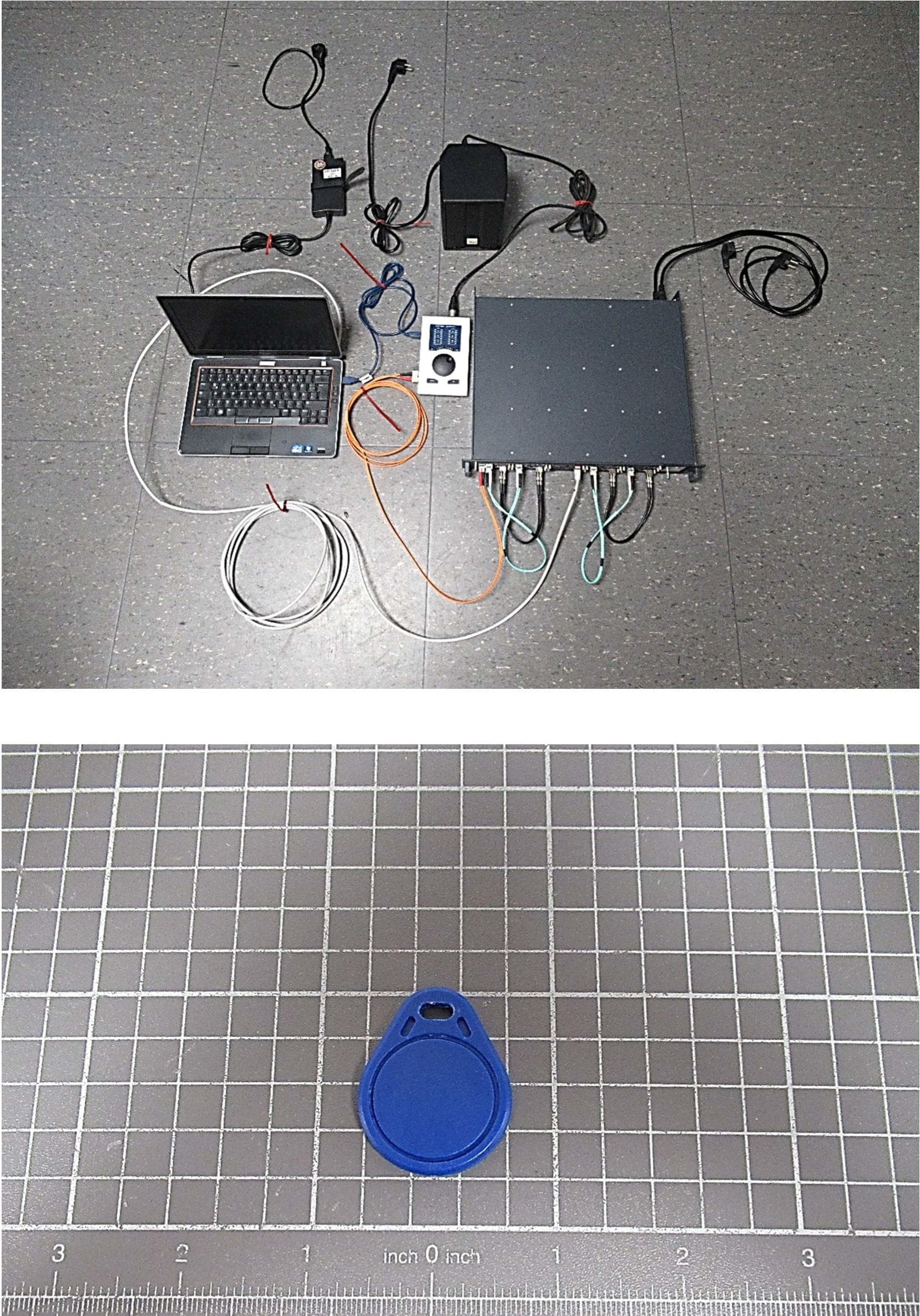
YFJART1024
Dec 11, 2023Modular Intercom Matrix System
Equipment Class
DXX - Part 15 Low Power Communication Device Transmitter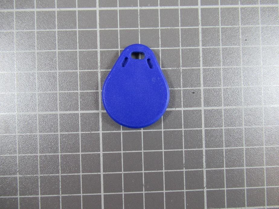
YFJDIS1024
Feb 25, 2021Display unit with integrated RFID reader
Equipment Class
DXX - Part 15 Low Power Communication Device Transmitter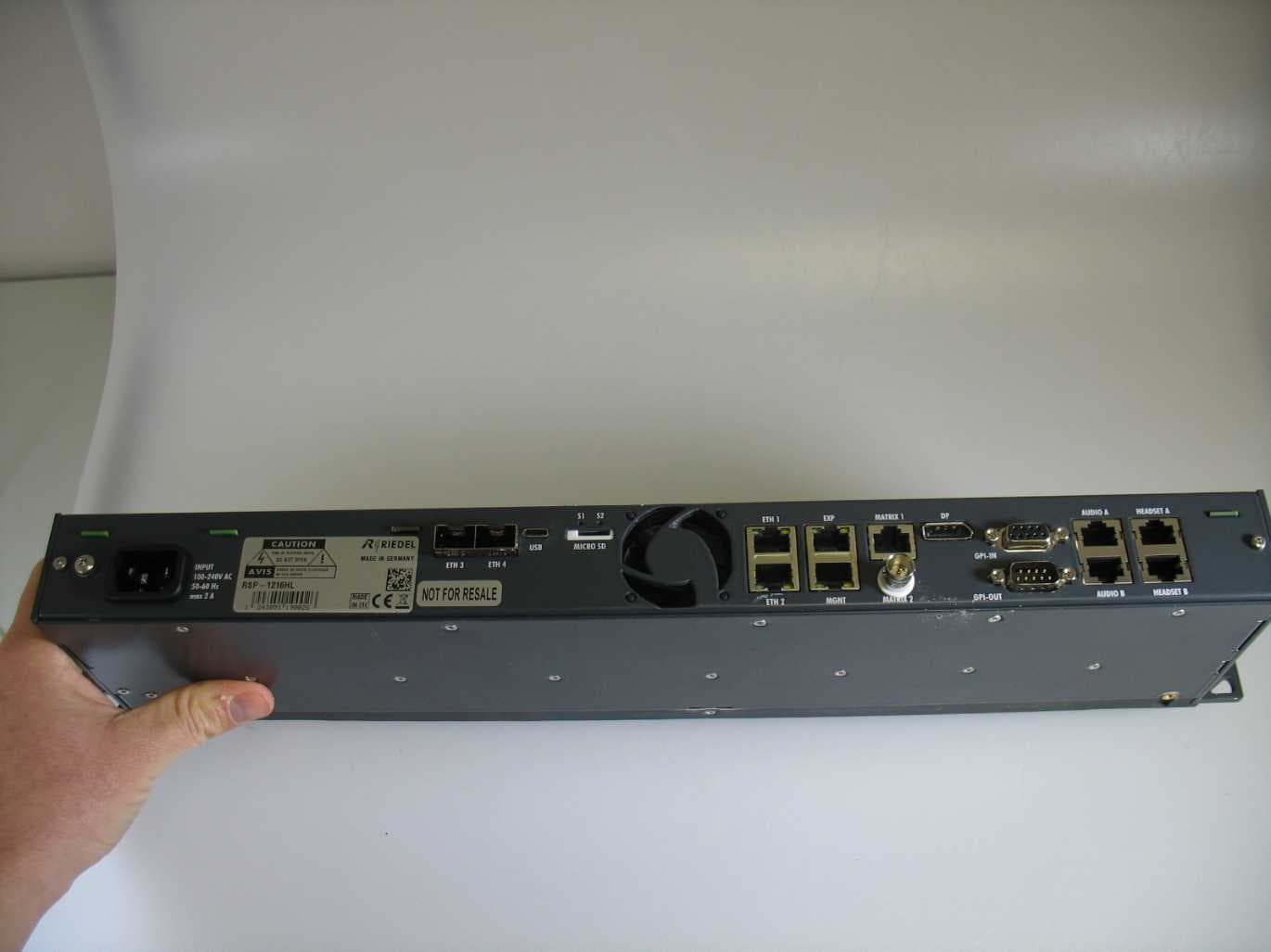
YFJRSP1216HL
Oct 28, 202019Inch/1RU 1200 series SmartPanel Intercom Platform with 16 hybrid lever keys
Equipment Class
DXX - Part 15 Low Power Communication Device Transmitter