YGK-T302ABluetooth Headset
SHENZHEN ROMAN TECHNOLOGY CO.,LTD.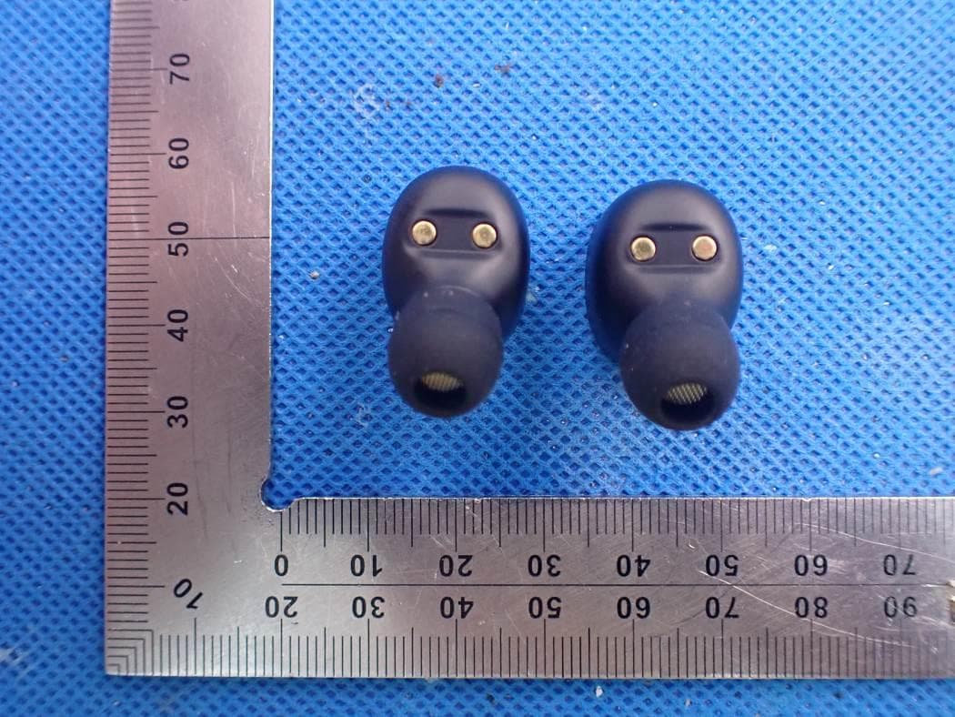
Click to zoom
Application Details
- Equipment Class
- DSS - Part 15 Spread Spectrum Transmitter
- Date of Grant
- Sep 23, 2020
- Application Purpose
- Original Equipment
- Date of Application
- Sep 23, 2020
- Equipment Note
- Bluetooth Headset
- Frequency Range
- 2402.00000000 - 2480.00000000
- Country
- China
Documents & Files
Document Text
Text extracted from the exhibit documents filed with the FCC. Open a document above to read the original.
Users Manual
1 / 15 T302A真无线蓝牙耳机中英文说明书 T302A Bluetooth headset in Chinese and English 使用说明书 User Manual 概述 Welcome 感谢您选择了我们的产品。本公司蓝牙耳机外观设计时尚、功能强大、兼容性好,让您真正体验到无线打电话、听 音乐的乐趣!是您办公、外出、驾驶的最佳选择! Thank you for choosing our products. The company Bluetooth earphone has a fashionable design, powerful functions, and high compatibility, providing you with hands-free convenience in making calls and listening to music. It is your best choice in office and during traveling and driving. 2 / 15 蓝牙无线技术 Bluetooth Wireless Technology 通过蓝牙无线技术,您无需使用线缆就可以将耳机连接至与其相兼容的通信设备。蓝牙无线连接无需保持手机与耳 机相互正对,但两者之间的最大距离不应该超过10米(约30英尺),蓝牙无线连接可能因墙壁等障碍物或其他电 子设备而受到干扰。 With the Bluetooth wireless technology, you can connect the earphone to its compatible communication devices without using cables. The Bluetooth wireless connection allows you to use a cell phone without holding it against the earphone, but the maximum distance between them cannot exceed 10 meters (about30 feet). The Bluetooth wireless connection may be interfered by obstacles (such as walls) or other electronic devices. 在某些地区,使用蓝牙无线技术可能受到一些限制,请向当地主管部门或服务供应商咨询。 In some areas, use of the Bluetooth wireless technology may be subject to some constraints. Please consult your local authority or service provider for details. 3 / 15 使用前请为耳机进行一次完全充电(充电方法参考本书充电篇),同时选择与该耳机相兼容的手机和其他蓝牙终端 设备进行配对(配对方法参照基本操作篇)。 Fully charge the earphone before using. For details about how to charge the earphone, see "Charger and Battery" in this manual. Meanwhile, choose the cell phone that is compatible with the earphone or other Bluetooth devices to pair with the earphone. For details about pairing, see "Basic Operations". 温馨提示:请勿使用信用卡或其他磁性存储器介质靠近耳机,以免因消磁而失去存储信息。 Tip: Keep the earphone away from your credit card or other magnetic storage media; otherwise, the stored information may be lost due to demagnetization. 4 / 15 蓝牙耳机配对连接方法(注:以苹果手机为例) How to connect with the Bluetooth earphone (Note: Use iPhone for example) 为方便用户操作,在您购买此产品前出厂时已经完成两只蓝牙耳机之间的左、右声道立体音互连配对设置! For customer’s convenience of operation, the left- and right-channel stereo of the two Bluetooth earphones has been paired and connected before leaving factory. ●耳机初次使用 ●Initial use of the earphone 1、初次使用时,将充电盒进行充电后充电盒白色LED灯亮,左(L) 、右( R )耳机放入充电盒进行激活。 1. For the first use, after charging with the charging box, the white LED of the charging box is on; place the left (L) and right (R) headphones in the charging box for activation. 2、打开充电盒盖子耳机会自动开机并进入配对状态,耳机有提示音。 2. open the cover of the charging box, and the headset is automatically powered on and enters pairing status, and have a prompt tone when completing the TWS pairing. 3、打开手机蓝牙,搜索蓝牙耳机设备。搜索到蓝牙耳机后,点击配对,完成连接。 5 / 15 3. Start the Bluetooth on your phone, and search for Bluetooth headset.After the Bluetooth headset is found, click Pair to complete connection. 6 / 15 基本操作 Basic Operations ○ 自动开关机:使用时只需打开充电盒的盖子,耳机自动开机且TWS连接成功,配对超时3分钟自动关机,将耳机放 入充电盒内并合上充电盖,耳机断开手机连接自动关机进入充电状态。 Auto power-on/off: Just open the cover of the charging box, and the headset is automatically powered on, with TWS successfully connected. If pairing exceeds 3 minutes, the headset is automatically powered off. Put the headset into the charging box, close the charging cover, and the headset is disconnected from the mobile phone, automatically powered off, and enters charging status. ○ 手动TWS配对:在左右耳开机并进入配对状态下,敲击两下进入TWS配对,此时红蓝灯同时闪烁,配对成功后左 声道耳机伴有提示音,右声道耳机也伴有提示音。 Manual TWS pairing: When the left and right earphones enter the pairing state, double-tap an earphone to start TWS pairing, and the indicator blinks in red and blue alternatively. After the successful paring, a voice prompt can be heard on both the left and right earphones. ○ 连接:左、右耳机TWS配对完成后,打开充电盒盖子耳机会自动开机并进入配对状态,手机搜索配对名,点击连 接,会有电子提示音。 Connection: After the left and right earpieces completes TWS pairing, open the cover of the charging box, and the headset is automatically powered on and enters pairing status. Search for the pairing target name on your mobile phone, tap Connect, and an electronic prompt tone rings. 7 / 15 ○ 来电接听:来电时,连续敲击两下耳机(L)或耳机( R)即可接听电话,伴有"嘟"提示音。 Receiving a call: When there is an incoming call, you can double-tap the left earphone (L) or right earphone (R) to receive the call, and meanwhile a "Beep" prompt tone can be heard. ○ 来电挂断:通话中, 连续敲击两下耳机(L)或耳机( R)即可挂断电话,伴有"嘟"提示音。 Terminating a call: During a call, you can double-tap the left earphone (L) or right earphone (R) to terminate the call, and meanwhile a "Beep" prompt tone can be heard. ○ 取消电话拨号:电话拨出时,连续敲击两下耳机(L)或耳机(R)实现取消去电功能,并伴有"嘟"提示音。 Canceling a call: After you dial a call, you can double-tap the left earphone (L) or right earphone (R) to cancel the call, and meanwhile a "Beep" prompt tone can be heard. ○ 音乐播放暂停:耳机处于播放音乐状态时,连续敲击两下耳机(L)或耳机(R)可实现歌曲暂停,重复操作可实 现歌曲播放。 Playing or pausing music: When the music is being played, you can double-tap the left earphone (L) or right earphone (R) to pause the music, or repeat the same operation to play the music again. ○ 自动回连:开机后,耳机会先主动回连最后配对过的一台设备。 Automatic re-connection: After the earphone are powered on, they are actively re-connected to the last paired one devices. 8 / 15 ○ iOS电池电量显示:与iOS系统连接后可显示耳机电池电量状态。 iOS battery level display: After the earphone is connected to the iOS, the battery level of the earphone can be displayed. ○ 低压报警:伴有提示音,每间隔5分钟提示一次直至关机。 Low-voltage alarm: A voice prompt is played every 5 minutes until the headset is powered off. ○ 防丢警示:走远或异常断开时,会有提示音,3分钟回连时间,3分钟后自动关机。 Anti-lost alarm: When the headset is far away from you or is abnormally disconnected, a voice prompt can be heard. An attempt will be made to reconnect the headset in 3 minutes. Three minutes later, the headset will be automatically powered off. 9 / 15 充电器和电池 Charger and Battery 使用任何充电器为本耳机充电前,请先检查充电器的规格标注是否符合要求(建议充电器输出电压为:DC5V+/-0.25V, 输出电流为:100mA-500mA ),充电电压过高极有可能会损坏蓝牙耳机。 Before using any charger to charge this earphone, check whether the specifications of the charger meet requirements. The recommended output voltage of the charger is DC5V+/-0.25V, and the recommended output current …
Text truncated - open the document above for the full version.
Cover Letter(s)
SHENZHEN ROMAN TECHNOLOGY CO., LTD. Sep.22, 2020 Office of Engineering Technology Federal Communications Commission 7435 Oakland Mills Road Columbia, MD 21046 USA Subject: Explanation of differences between product types FCC ID : YGK-T302A Model Number: T302A, T202, T202A, T202B, T202C, T202S, T203, T206, T301D, T301P, T302P, T306, T306A, T502, T502A, T502B, T502C, T502S To Whom It May Concern: We, The SHENZHEN ROMAN TECHNOLOGY CO., LTD. hereby declare that the model : T202, T202A, T202B, T202C, T202S, T203, T206, T301D, T301P, T302P, T306, T306A, T502, T502A, T502B, T502C, T502S is identical with the model : T302A, except the model name. Except for the different above, no other modification is performed. Sincerely, Signature: SHENZHEN ROMAN TECHNOLOGY CO., LTD. Contact person: Yanhui Cao
Cover Letter(s)
SHENZHEN ROMAN TECHNOLOGY CO., LTD. Agent Authorization Company: SHENZHEN ROMAN TECHNOLOGY CO., LTD. Address: Floor4, building, Fengmenao Industrial Park, Gangtou, shenzhen, China Product Name: Bluetooth Headset Model Number(s): T302A, T202, T202A, T202B, T202C, T202S, T203, T206, T301D, T301P, T302P, T306, T306A, T502, T502A, T502B, T502C, T502S Product Description: Bluetooth Headset We authorize MiCOM Labs Inc., 575 Boulder Court, Pleasanton, California 94566, USA, to act on our behalf on all matters concerning the certification of above named equipment. We declare that MiCOM Labs Inc. is allowed to forward all information related to the approval and certification of equipment to the regulatory agencies as required and to discuss any issues concerning the approval application. Any and all acts carried out by MiCOM Labs on our behalf shall have the same effect as acts of our own. Signature: Date: 2020-09-22 Name: Yanhui Cao Company: SHENZHEN ROMAN TECHNOLOGY CO., LTD.
Cover Letter(s)
SHENZHEN ROMAN TECHNOLOGY CO., LTD. Office of Engineering Technology Federal Communications Commission 7435 Oakland Mills Road Columbia, MD 21046 USA Date: 2020-09-16 Subject; Request for Confidentiality FCC ID: YGK-T302A To Whom It May Concern, Pursuant to the provisions of the Commission’s rules Title 47 Sections §0.457 and §0.459, we are requesting the Commission to withhold the following attachment(s) as confidential documents from public disclosure indefinitely. These documents contain detailed system and equipment descriptions and are considered as proprietary information in operation of the equipment. The public disclosure of these documents might be harmful to our company and would give competitors an unfair advantage in the market. Schematic Diagram Block Diagram Parts List Operational Description Tune-up Procedure In additional to above mentioned documents, in order to comply with the marketing regulations in Title 47 CFR §2.803 and the importation rules in Title 47 CFR §2.1204, while ensuring that business sensitive information remains confidential until the actual marketing of newly authorized devices, we request Short Term Confidentiality of the following attachment(s); External Photos Test Setup Photos Internal Photos User Manual For 45 days, pursuant to Public Notice DA 04-1705. OR For 180 days pursuant to KDB 726920 D01. It is our understanding that all measurement test reports, FCC ID label format and correspondence during the certification review process cannot be granted as confidential documents and this information will be available for public review once the grant of equipment authorization is issued. Sincerely SHENZHEN ROMAN TECHNOLOGY CO., LTD. Contact person: Yanhui Cao
External Photos
External Photos WHOLE VIEW OF EUT TOP VIEW OF EUT BOTTOM VIEW OF EUT FRONT VIEW OF EUT BACK VIEW OF EUT LEFT VIEW OF EUT RIGHT VIEW OF EUT
ID Label/Location Info
FCC ID Label Location The product does not have enough space to place the label, and FCC ID label is reflected in the user manual, as below:
Internal Photos
Internal Photos Left OPEN VIEW OF EUT VIEW OF BATTERY INTERNAL VIEW OF EUT-1 INTERNAL VIEW OF EUT-2 BT Antenna INTERNAL VIEW OF EUT-3 Right OPEN VIEW OF EUT VIEW OF BATTERY INTERNAL VIEW OF EUT-1 BT Antenna INTERNAL VIEW OF EUT-2 INTERNAL VIEW OF EUT-3
RF Exposure Info
RF EXPOSURE EVALUATION 1. PRODUCT INFORMATION Product Description Bluetooth Headset Model Name T302A, T202, T202A, T202B, T202C, T202S, T203, T206, T301D, T301P, T302P, T306, T306A, T502, T502A, T502B, T502C, T502S FCC ID YGK-T302A 2. EVALUATION METHOD According to 447498 D01 General RF Exposure Guidance v05 The 1-g and 10-g SAR test exclusion thresholds for 100 MHz to 6 GHz at test separation distances ≤ 50 mm are determined by: [(max. power of channel, including tune-up tolerance, mW)/(min. test separation distance, mm)] ·[√f(GHz)] ≤ 3.0 for 1-g SAR and ≤ 7.5 for 10-g extremity SAR. Where f(GHz) is the RF channel transmit frequency in GHz Power and distance are rounded to the nearest mW and mm before calculation 3. CALCULATION BR/EDR: P t = 6.859dBm=4.85mW The value of the Maximum output power P t is referred to the test report of the CFR47 §15.247. The result for RF exposure evaluation SAR=(4.85mW /5mm) .[√2.402GHz)]=1.504<3.0 for 1-g SAR and ≤ 7.5 for 10-g extremity SAR. 4. CONCLUSION The SAR evaluation is not required.
Test Report
Page 1 of 75 FCC Test Report Report No.: AGC00149200803FE03 FCC ID : YGK-T302A APPLICATION PURPOSE : Original Equipment PRODUCT DESIGNATION : Bluetooth Headset BRAND NAME : ROMAN MODEL NAME : T302A, T202, T202A, T202B, T202C, T202S, T203, T206, T301D, T301P, T302P, T306, T306A, T502, T502A, T502B, T502C, T502S APPLICANT : SHENZHEN ROMAN TECHNOLOGY CO., LTD. DATE OF ISSUE : Sep. 15,2020 STANDARD(S) : FCC Part 15.247 REPORT VERSION : V1.0 Attestation of Global Compliance (Shenzhen) Co., Ltd Report No.: AGC00149200803FE03 Page 2 of 75 REPORT REVISE RECORD Report Version Revise Time Issued Date Valid Version Notes V1.0 / Sep. 15,2020 Valid Initial Release Report No.: AGC00149200803FE03 Page 3 of 75 TABLE OF CONTENTS 1. VERIFICATION OF CONFORMITY ............................................................................................................... 5 2. GENERAL INFORMATION ............................................................................................................................ 7 2.1. PRODUCT DESCRIPTION ..................................................................................................................... 7 2.2. TABLE OF CARRIER FREQUENCYS ..................................................................................................... 7 2.3. RECEIVER INPUT BANDWIDTH ............................................................................................................ 8 2.4. EXAMPLE OF A HOPPING SEQUENCY IN DATA MODE ....................................................................... 8 2.5. EQUALLY AVERAGE USE OF FREQUENCIES AND BEHAVIOUR ........................................................ 8 2.6. RELATED SUBMITTAL(S) / GRANT (S) .................................................................................................. 9 2.7. TEST METHODOLOGY .......................................................................................................................... 9 2.8. SPECIAL ACCESSORIES ....................................................................................................................... 9 2.9. EQUIPMENT MODIFICATIONS .............................................................................................................. 9 2.10. ANTENNA REQUIREMENT .................................................................................................................. 9 3. MEASUREMENT UNCERTAINTY ............................................................................................................... 10 4. DESCRIPTION OF TEST MODES ............................................................................................................... 11 5. SYSTEM TEST CONFIGURATION ............................................................................................................. 12 5.1. CONFIGURATION OF EUT SYSTEM ................................................................................................... 12 5.2. EQUIPMENT USED IN TESTED SYSTEM ............................................................................................ 12 5.3. SUMMARY OF TEST RESULTS ............................................................................................................ 12 6. TEST FACILITY ........................................................................................................................................... 13 7. PEAK OUTPUT POWER ............................................................................................................................. 14 7.1. MEASUREMENT PROCEDURE ........................................................................................................... 14 7.2. TEST SET-UP (BLOCK DIAGRAM OF CONFIGURATION) ................................................................... 14 7.3. LIMITS AND MEASUREMENT RESULT ............................................................................................... 15 8. 20DB BANDWIDTH ..................................................................................................................................... 21 8.1. MEASUREMENT PROCEDURE ........................................................................................................... 21 8.2. TEST SET-UP (BLOCK DIAGRAM OF CONFIGURATION) ................................................................... 21 8.3. LIMITS AND MEASUREMENT RESULTS ............................................................................................. 22 9. CONDUCTED SPURIOUS EMISSION ........................................................................................................ 28 9.1. MEASUREMENT PROCEDURE ........................................................................................................... 28 Report No.: AGC00149200803FE03 Page 4 of 75 9.2. TEST SET-UP (BLOCK DIAGRAM OF CONFIGURATION) ................................................................... 28 9.3. MEASUREMENT EQUIPMENT USED .................................................................................................. 28 9.4. LIMITS AND MEASUREMENT RESULT ............................................................................................... 28 10. RADIATED EMISSION ............................................................................................................................... 41 10.1. MEASUREMENT PROCEDURE ......................................................................................................... 41 10.2. TEST SETUP ....................................................................................................................................... 43 10.3. LIMITS AND MEASUREMENT RESULT ............................................................................................. 44 10.4. TEST RESULT ..................................................................................................................................... 44 11. NUMBER OF HOPPING FREQUENCY ............................................…
Text truncated - open the document above for the full version.
Test Report
Report No.: AGC00149200803FE03 Page 52 of 75 EUT Bluetooth Headset Model Name T302A Temperature 25°C Relative Humidity 55.4% Pressure 960hPa Test Voltage Normal Voltage Test Mode Mode 9 Antenna Horizontal PK AV RESULT: PASS Report No.: AGC00149200803FE03 Page 53 of 75 EUT Bluetooth Headset Model Name T302A Temperature 25°C Relative Humidity 55.4% Pressure 960hPa Test Voltage Normal Voltage Test Mode Mode 9 Antenna Vertical PK AV RESULT: PASS Note: The factor had been edited in the “Input Correction” of the Spectrum Analyzer. The 8DPSK modulation is the worst case and recorded in the report. Report No.: AGC00149200803FE03 Page 54 of 75 11. NUMBER OF HOPPING FREQUENCY 11.1. MEASUREMENT PROCEDURE The EUT shall have its hopping function enabled. Use the following spectrum analyzer settings: 1. Span: The frequency band of operation. Depending on the number of channels the device supports, it may be necessary to divide the frequency range of operation across multiple spans, to allow the individual channels to be clearly seen. 2. RBW: To identify clearly the individual channels, set the RBW to less than 30% of the channel spacing or the 20 dB bandwidth, whichever is smaller. 3. VBW ≥ RBW. Sweep: Auto. Detector function: Peak. Trace: Max hold. 4. Allow the trace to stabilize. 11.2. TEST SETUP (BLOCK DIAGRAM OF CONFIGURATION) Same as described in section 8.2 11.3. MEASUREMENT EQUIPMENT USED The same as described in section 6 11.4. LIMITS AND MEASUREMENT RESULT TOTAL NO. OF HOPPING CHANNEL LIMIT (NO. OF CH) MEASUREMENT (NO. OF CH) RESULT >=15 79 PASS TEST PLOT FOR NO. OF TOTAL CHANNELS Note: The GFSK modulation is the worst case and recorded in the report. Report No.: AGC00149200803FE03 Page 55 of 75 12. TIME OF OCCUPANCY (DWELL TIME) 12.1. MEASUREMENT PROCEDURE The EUT shall have its hopping function enabled. Use the following spectrum analyzer settings: 1. Span: Zero span, centered on a hopping channel. 2. RBW shall be≤channel spacing and where possible RBW should be set >> 1 / T, where T is the expected dwell time per channel. 3. Sweep: As necessary to capture the entire dwell time per hopping channel; where possible use a video trigger and trigger delay so that the transmitted signal starts a little to the right of the start of the plot. The trigger level might need slight adjustment to prevent triggering when the system hops on an adjacent channel; a second plot might be needed with a longer sweep time to show two successive hops on a channel. 4. Detector function: Peak. Trace: Max hold. 5. Use the marker-delta function to determine the transmit time per hop. 6. Repeat the measurement using a longer sweep time to determine the number of hops over the period specified in the requirements. The sweep time shall be equal to, or less than, the period specified in the requirements. Determine the number of hops over the sweep time and calculate the total number of hops in the period specified in the requirements, using the following equation: (Number of hops in the period specified in the requirements) = (number of hops on spectrum analyzer) × (period specified in the requirements / analyzer sweep time) 7. The average time of occupancy is calculated from the transmit time per hop multiplied by the number of hops in the period specified in the requirements. 12.2. TEST SETUP (BLOCK DIAGRAM OF CONFIGURATION) Same as described in section 8.2 12.3. MEASUREMENT EQUIPMENT USED The same as described in section 6 12.4. LIMITS AND MEASUREMENT RESULT Channel Time of Pulse for DH5 (ms) Number of hops in the period specified in the requirements Sweep Time (ms) Limit (ms) Low 2.897 27*4 312.876 400 Middle 2.897 27*4 312.876 400 High 2.897 26*4 301.288 400 Note: The 8DPSK modulation is the worst case and recorded in the report. Report No.: AGC00149200803FE03 Page 56 of 75 TEST PLOT OF LOW CHANNEL Report No.: AGC00149200803FE03 Page 57 of 75 TEST PLOT OF MIDDLE CHANNEL Report No.: AGC00149200803FE03 Page 58 of 75 TEST PLOT OF HIGH CHANNEL Report No.: AGC00149200803FE03 Page 59 of 75 13. FREQUENCY SEPARATION 13.1. MEASUREMENT PROCEDURE The EUT shall have its hopping function enabled. Use the following spectrum analyzer settings: 1. Span: Wide enough to capture the peaks of two adjacent channels. 2. RBW: Start with the RBW set to approximately 30% of the channel spacing; adjust as necessary to best identify the center of each individual channel. 3. Video (or average) bandwidth (VBW) ≥ RBW. 4. Sweep: Auto. e) Detector function: Peak. f) Trace: Max hold. g) Allow the trace to stabilize. Use the marker-delta function to determine the separation between the peaks of the adjacent channels. 13.2. TEST SETUP (BLOCK DIAGRAM OF CONFIGURATION) Same as described in section 6.2 13.3. MEASUREMENT EQUIPMENT USED The same as described in section 6.3 13.4. LIMITS AND MEASUREMENT RESULT CHANNEL CHANNEL SEPARATION LIMIT RESULT MHz Pass CH38-CH39 1 20 dB BW TEST PLOT FOR FREQUENCY SEPARATION Note: The GFSK modulation is the worst case and recorded in the report. Report No.: AGC00149200803FE03 Page 60 of 75 APPENDIX A: PHOTOGRAPHS OF TEST SETUP RADIATED EMISSION TEST SETUP BELOW 1GHz RADIATED EMISSION TEST SETUP ABOVE 1GHz Report No.: AGC00149200803FE03 Page 61 of 75 CONDUCTED TEST SETUP Report No.: AGC00149200803FE03 Page 62 of 75 APPENDIX B: PHOTOGRAPHS OF EUT WHOLE VIEW OF EUT TOP VIEW OF EUT Report No.: AGC00149200803FE03 Page 63 of 75 BOTTOM VIEW OF EUT FRONT VIEW OF EUT Report No.: AGC00149200803FE03 Page 64 of 75 BACK VIEW OF EUT LEFT VIEW OF EUT Report No.: AGC00149200803FE03 Page 65 of 75 RIGHT VIEW OF EUT Left OPEN VIEW OF EUT Report No.: AGC00149200803FE03 Page 66 of 75 VIEW OF BATTERY INTERNAL VIEW OF EUT-1 BT Antenna Report No.: AGC00149200803FE03 Page 67 of 75 INTERNAL VIEW OF EUT-2 INTERNAL VIEW OF EUT-3 Report No.: AGC00149200803FE03 Page 68 of 75 Right OPEN VIEW OF EUT VIEW OF BATTERY Report No.: AGC00149200803FE03 Page 69 of 75 INTERNAL VIEW OF EUT-1 INTERNAL VIEW OF EUT-2 BT Antenna
Test Report
Report No.: AGC00149200803FE03 Page 70 of 75 INTERNAL VIEW OF EUT-3 Charging Dock TOP VIEW OF EUT Report No.: AGC00149200803FE03 Page 71 of 75 BOTTOM VIEW OF EUT FRONT VIEW OF EUT Report No.: AGC00149200803FE03 Page 72 of 75 BACK VIEW OF EUT LEFT VIEW OF EUT Report No.: AGC00149200803FE03 Page 73 of 75 RIGHT VIEW OF EUT VIEW OF EUT(port)-1 Report No.: AGC00149200803FE03 Page 74 of 75 VIEW OF EUT(port)-2 OPEN VIEW OF EUT Report No.: AGC00149200803FE03 Page 75 of 75 VIEW OF BATTERY INTERNAL VIEW OF EUT-1 Report No.: AGC00149200803FE03 Page 76 of 75 INTERNAL VIEW OF EUT-2 ----END OF REPORT---- Conditions of Issuance of Test Reports 1. All samples and goods are accepted by the Attestation of Global Compliance (Shenzhen) Co., Ltd (the “Company”) solely for testing and reporting in accordance with the following terms and conditions. The company provides its services on the basis that such terms and conditions constitute express agreement between the company and any person, firm or company requesting its services (the “Clients”). 2. Any report issued by Company as a result of this application for testing services (the “Report”) shall be issued in confidence to the Clients and the Report will be strictly treated as such by the Company. It may not be reproduced either in its entirety or in part and it may not be used for advertising or other unauthorized purposes without the written consent of the Company. The Clients to whom the Report is issued may, however, show or send it, or a certified copy thereof prepared by the Company to its customer, supplier or other persons directly concerned. The Company will not, without the consent of the Clients, enter into any discussion or correspondence with any third party concerning the contents of the Report, unless required by the relevant governmental authorities, laws or court orders. 3.The Company shall not be called or be liable to be called to give evidence or testimony on the Report in a court of law without its prior written consent, unless required by the relevant governmental authorities, laws or court orders. 4. The non-CMA report issued by AGC is only permitted to be used by the client as internal reference use and shall not be used for public demonstration purpose. 5. In the event of the improper use of the report as determined by the Company, the Company reserves the right to withdraw it, and to adopt any other additional remedies which may be appropriate. 6. Samples submitted for testing are accepted on the understanding that the Report issued cannot form the basis of, or be the instrument for, any legal action against the Company. 7. The Company will not be liable for or accept responsibility for any loss or damage however arising from the use of information contained in any of its Reports or in any communication whatsoever about its said tests or investigations. 8.Clients wishing to use the Report in court proceedings or arbitration shall inform the Company to that effect prior to submitting the sample for testing. 9. The Company is not responsible for recalling the electronic version of the original report when any revision is made to them. The Client assumes the responsibility to providing the revised version to any interested party who uses them. 10. Subject to the variable length of retention time for test data and report stored hereinto as otherwise specifically required by individual accreditation authorities, the Company will only keep the supporting test data and information of the test report for a period of six years. The data and information will be disposed of after the aforementioned retention period has elapsed. Under no circumstances shall we provide any data and information which has been disposed of after retention period. Under no circumstances shall we be liable for damage of any kind, including (but not limited to) compensatory damages, lost profits, lost data, or any form of special, incidental, indirect, consequential or punitive damages of any kind, whether based on breach of contract of warranty, tort (including negligence), product liability or otherwise, even if we are informed in advance of the possibility of such damages.
Test Setup Photos
Test Setup Photos RADIATED EMISSION TEST SETUP BELOW 1GHz RADIATED EMISSION TEST SETUP ABOVE 1GHz CONDUCTED TEST SETUP
Contact Information
Applicant
Yanhui Cao
Technical Contact
Test Firm
Attestation of Global Compliance (Shenzhen) Co., LDoris Li
[email protected]+86-755-25234088
Technical Specifications
| # | Rule Parts | Frequency Range | Power Output |
|---|---|---|---|
| 1 | 15C | 2.40 GHz - 2.48 GHz | 4.90 mW |
Other Applications from SHENZHEN ROMAN TECHNOLOGY CO.,LTD.
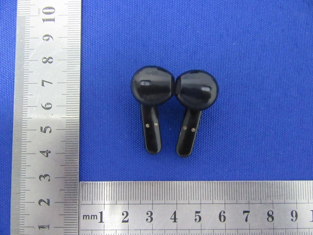
YGKTS16C
May 19, 2021Bluetooth Headset
Equipment Class
DSS - Part 15 Spread Spectrum Transmitter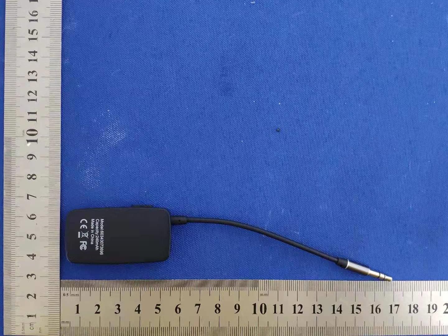
YGK-J205
Mar 06, 2021Bluetooth receiver
Equipment Class
DSS - Part 15 Spread Spectrum TransmitterYGKR6100
Nov 16, 2015Bluetooth headset
Equipment Class
DXX - Part 15 Low Power Communication Device Transmitter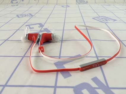
YGKS370
Mar 16, 2015Bluetooth Headset
Equipment Class
DXX - Part 15 Low Power Communication Device Transmitter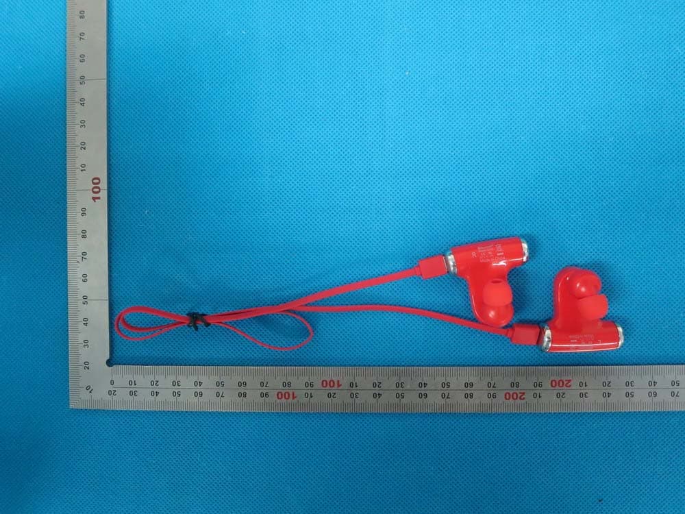
YGKS530
Dec 16, 2014Bluetooth Headset
Equipment Class
DTS - Digital Transmission System