YGS0019746189Wireless Audio Link
Vaddio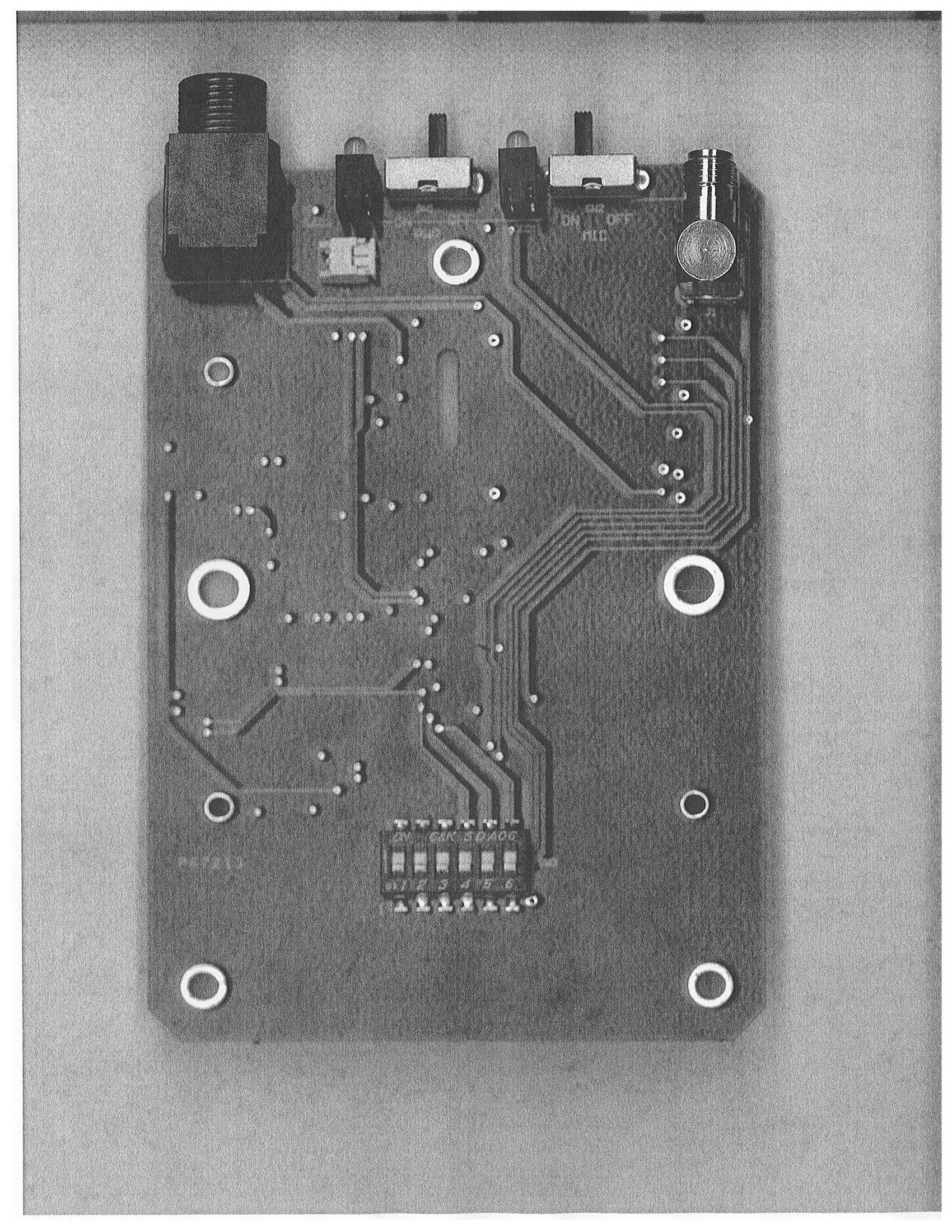
Click to zoom
Application Details
- Equipment Class
- DXX - Part 15 Low Power Communication Device Transmitter
- Date of Grant
- Jun 07, 2010
- Application Purpose
- Original Equipment
- Date of Application
- Jun 07, 2010
- Equipment Note
- Wireless Audio Link
- Frequency Range
- 903.37000000 - 921.37000000
- Company
- Vaddio
- Country
- United States
Documents & Files
Document Text
Text extracted from the exhibit documents filed with the FCC. Open a document above to read the original.
Users Manual
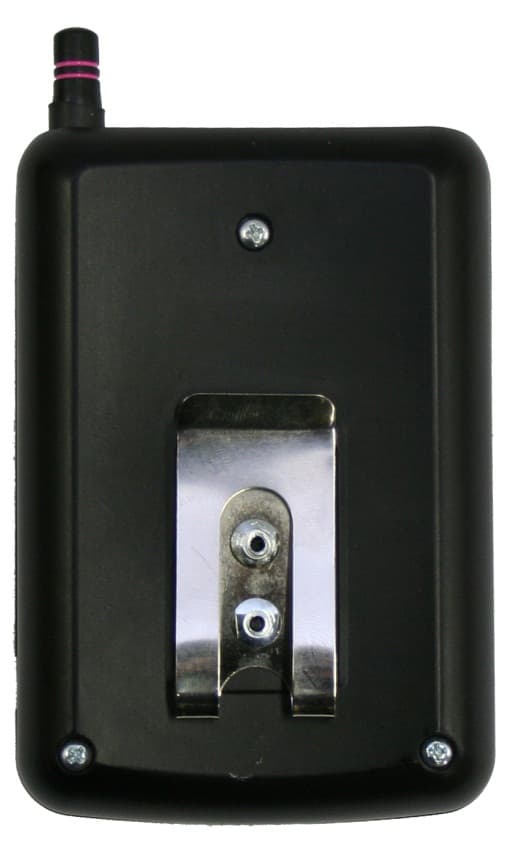
Preliminary Owner’s Manual AutoTrak Audio Interface, Lanyard and Belt Pack Unit Manual 341-XXXX Vaddio™ AutoTrak™ Audio Interface, Battery Belt Pack Transmitter and Presenter’s IR/Audio Lanyard Overview: The Audio Interface, Presenter’s IR Lanyard with Wireless Lavaliere Mic and Belt Pack are peripherals of AutoTrak System. The Lanyard contains IR LEDs within an IR transparent woven material and is used to track any presenter that wears it within range of the AutoTrak Cameras and Core Processor. The center medallion contains a microphone element that will pick up the speech of the presenter. The 32” cable from the lanyard to the Belt Pack is strain relieved on both ends and carries power from the Belt Pack to the IR LEDs and receives audio from the microphone element built into the Central Medallion. The Belt Pack holds the four (4) AA sized batteries and supplies power for the wireless audio transmitter and the IR LEDs. Intended Use: Before operating the product, please read the entire manual thoroughly. The product was designed, built and tested for use indoors, and with the provided power supply. The use of a power supply other than the approved Vaddio provided power supplies or outdoor operation has not been tested and could damage the product and/or create a potentially unsafe operating condition. Save These Instructions: The information contained in this manual will help you install and operate your Vaddio product. If these instructions are misplaced, Vaddio keeps copies of Specifications, Installation and User Guides and most pertinent product drawings for the Vaddio product line on the Vaddio website. These documents can be downloaded from www.vaddio.com free of charge. Important Safeguards: Read and understand all instructions before using. Do not operate any device if it has been dropped or damaged. In this case, a Vaddio technician must examine the product before operating. To reduce the risk of electric shock, do not immerse in water or other liquids and avoid extremely humid conditions. Front Panel Rear Panel 32” Cable Length Belt Pack Unit • Batteries, • Wireless Audio Transmitter • Lanyard Interface • Belt Clip on back Presenter’s Lanyard • 32” Strain Relieved Cable • Lavaliere Microphone • IR LEDs for Tracking • 24” Lanyard Length Camera and Electronic Products for Integrators Use only the approved power supplies provided with the system. Use of any unauthorized power supply will void any and all warranties. Central Medallion Preliminary Owner’s Manual AutoTrak Audio Interface, Lanyard and Belt Pack Unit Manual 341-XXXX Page 2 of 8 Compliance Information FCC Part 15 Compliance This equipment has been tested and found to comply with the limits for a Class B digital device, pursuant to Part 15, Subpart B, of the FCC Rules. These limits are designed to provide reasonable protection against harmful interference when the equipment is operated in a residential installation. This equipment generates, uses, and can radiate radio frequency energy and, if not installed and used in accordance with the instruction manual, may cause harmful interference to radio communications. However, there is no guarantee that interference will not occur in a particular installation. Operation of this equipment in a residential area is likely to cause harmful interference in which case the user will be required to correct the interference at his/her own expense. Operation is subject to the following two conditions: (1) This device may not cause interference, and (2) This device must accept any interference including interference that may cause undesired operation of the device. If the equipment does cause harmful interference to television or radio reception, which can be determined by turning the equipment on and off, the user is encouraged to correct the interference by one or more of the following measures: • Reorient or relocate the receiving antenna • Increase the distance between the equipment and the receiver • Connect the equipment to an electrical outlet on a circuit different from that to which the receiver is connected • Consult an experienced radio/TV technician for help Changes or modifications not expressly approved by Vaddio can affect emission compliance and could void the user’s authority to operate this equipment. Preliminary Owner’s Manual AutoTrak Audio Interface, Lanyard and Belt Pack Unit Manual 341-XXXX Page 3 of 8 Unpacking: Carefully remove the device and all of the parts from the packaging. Unpack and identify the following parts: • One (1) AutoTrak Audio Interface with 6.5” RP-SMA Right Angle Antenna • One (1) Belt Pack Unit with 2” RP-SMA Straight Antenna • One (1) Presenter’s Lanyard with attached 32” Cord • One (1) PowerRite 12 VDC, 1.0 Amp, Switching (100V to 250V, 50/60Hz) Power Supply • Documentation AutoTrak Audio Interface Front Panel Controls and Operating Instructions: 1) Power ON/OFF: This switch turns the power for the AutoTrak Audio Interface on or off. To use, push the power button until the blue LED is lit and the system is ready for operation. 2) Mic Mute: Touching this button will light the blue LED and will mute the microphone output at the interface. To un- mute, touch the button again and the LED will turn off and the audio path will be turned on. 3) Audio Level: This control is an audio taper 10K potentiometer and controls the audio level at the output of the AutoTrak Audio Interface. Audio input levels are preset from the factory. 4) System Status: This status indicator will light if the microphone signal is being received from the audio transmitter in the belt pack. If the microphone is recognized, the LED will light blue. AutoTrak Audio Interface Rear Panel and Operating Instructions: 1) 12 VDC, 1.0 Amp Power Connector: The 5.5mm OD and 2.5mm ID power connector should be plugged into the PowerRite power supply provided by Vaddio. Use of any unauthorized power supplies will void any and all warranties. 2) Audio Outputs: There are two (2) audio outpu…
Text truncated - open the document above for the full version.
Cover Letter(s)
Vaddio • 9433 Science Center Drive • Minneapolis, MN 55428 • Phone: 763-971-4400 • Fax: 763-971-4464 • www.vaddio.com
Cover Letter(s)
Vaddio • 9433 Science Center Drive • Minneapolis, MN 55428 • Phone: 763-971-4400 • Fax: 763-971-4464 • www.vaddio.com
Cover Letter(s)
TÜV America Inc. Phone: (651) 638-0297 19333 Wild Mountain Road Fax: (651) 638-0298 Taylor Falls, MN 55084 E-mail: [email protected] www.TUVamerica.com Management Service • Product Service • Industry Service • Automotive • BABT TÜV America Inc. is a subsidiary of TÜV SÜD Group. TÜV SÜD AMERICA INC 19333 WILD MOUNTAIN ROAD TAYLORS FALLS, MINNESOTA 55084-1786 ENGINEERING STATEMENT For Certification of Vaddio AutoTrak Belt Pack Unit Model No: 998-7210-000 FCC ID: YGS0019746189 FRN: 0019746189 I am an Electromagnetic Compatibility Engineer for TÜV SÜD AMERICA INC, Taylors Falls, Minnesota. My education and experience are a matter of record with the Federal Communications Commission. TÜV SÜD AMERICA INC has been authorized by William Fischer, Engineer, of Vaddio, to make Certification measurements of the above mentioned equipment. I attest that all testing done under my supervision was done in accordance with, and that the EUT fulfills the requirements of, the Federal Communications Commission's CFR 47 Part 15.249. Joel T. Schneider Senior Engineer Minnesota Wild River Lab TÜV SÜD America Product Service Tel: 651 604 4582 Fax: 651 638 0298 [email protected] Dated: 04 June 2010
ID Label/Location Info
2.125” W x 1.125” H For area underneath belt cli p VADDIO 9433 Science Center Drive, New Hope, MN 55428 763-971-4452 763-971-4464 FAX AutoTrak Belt Pack Unit FCC ID: YGS0019746189 This device complies with Part 15 of the FCC rules. Operation is subject to the following two conditions: 1) This device may not cause harmful interference, and, 2) This device must accept any interference received including interference that may cause undesired operation.
Operational Description
Vaddio • 9433 Science Center Drive • Minneapolis, MN 55428 • Phone: 763-971-4400 • Fax: 763-971-4464 • www.vaddio.com PRODUCT OPERATION OVERVIEW AUTOTRAK BPU DEVICE 5-28-10 • Device U3 monitors incoming DC voltage and current from the 4 AA batteries. • Device U9 regulates the incoming DC voltage to 4.5vdc for IR LED illumination. • Device U8 regulates the incoming DC voltage to 3.3vdc for all ICs on the device. • Device U12 regulates the incoming DC voltage to 3.3vdc for bias voltage to the microphone. • Device U4 is a PIC microprocessor which will monitor device U3 via an I2C bus, read status of mic switch, control power and mic LEDs and control Q3 which turns IR LEDs on or off. • Device U10 is the 903-922 mhz transmitter chip. It is supplied 3.3vdc, analog audio from the mic input, and can be put into power down mode via the mic control switch. • The antenna is a ¼ wave monopole design attached to the PCB via a reverse polarity SMA connector. The RP-SMA connector is fed from device U10 thru a 5db attenuation T-pad for FCC compliance. • Bits 1, 2 and 3 of SW3 control the transmit frequency (channel) of device U10, as per instruction manual. Bit 6 of SW3 may be set to disable IR LEDs if desired. • Jack J2 connects the external IR LED lanyard and microphone to the BPU device. • There are no provisions for charging the 4 AA cells. Batteries must be removed from unit and replaced or recharged. William Fischer Engineer Vaddio LLC
Test Report
TÜV SÜD AMERICA INC 19333 Wild Mountain Road Taylors Falls MN 55084-1786 Tel: 651 638 0297 Fax: 651 638 0298 Rev. 071107 TEST RESULT SUMMARY FCC Part 15 Subpart C Section 15.249 MANUFACTURER Vaddio 9433 Science Center Drive New Hope MN 55428 DESCRIPTION OF EQUIPMENT Wireless audio link and IR LED illuminator NAME OF EQUIPMENT AutoTrak Belt Pack Unit MODEL NUMBER(S) TESTED 998-7210-000 TEST REPORT NUMBER WC1003764 TEST DATE(S) 06 May 2010 TÜV SÜD America Inc, as an independent testing laboratory, declares that the equipment tested as specified above conforms to the electromagnetic compatibility requirements of FCC Part 15 Subpart C Sections 15.249 "Operation within the bands 902-928 MHz, 2400-2483.5 MHz, 5725-5875 MHz and 24.0-24.25 GHz”. It is the manufacturer's responsibility to assure that additional production units of this model are manufactured with identical electrical and mechanical characteristics. Any modifications necessary for compliance made during testing on the above mentioned date(s) must be implemented in all production units for compliance to be maintained. Date: 07 June 2010 Tested by: Approved by: Location: Taylors Falls MN Greg Jakubowski Joel T Schneider USA Senior EMC Technician Senior EMC Engineer Not Transferable TÜV SÜD AMERICA INC 19333 Wild Mountain Road Taylors Falls MN 55084-1786 Tel: 651 638 0297 Fax: 651 638 0298 Rev. 071107 EMC TEST REPORT Test Report No. WC1003764 Date of issue: 07 June 2010 Description of Equipment Wireless audio link and IR LED illuminator Model No(s) Tested 998-7210-000 Serial No(s) Tested n/a Manufacturer Vaddio 9433 Science Center Drive New Hope MN 55428 Test Result Positive Negative TÜV SÜD America Inc reports apply only to the specific samples tested under stated test conditions. It is the manufacturer's responsibility to assure that additional production units of this model are manufactured with identical electrical and mechanical components. TÜV SÜD America Inc shall have no liability for any deductions, inferences or generalizations drawn by the client or others from TÜV SÜD America Inc issued reports. This report is the confidential property of the client. As a mutual protection to our clients, the public and ourselves, extracts from the test report shall not be reproduced except in full without our written approval. This report shall not be used by the client to claim product endorsement by NVLAP, NIST, or any agency of the US government. TÜV SÜD America Inc and its professional staff hold government and Professional organization certifications and are members of AAMI, ACIL, AEA, ANSI, IEEE, NARTE, and VCCI. Test Report WC10037641 of 26 TÜV SÜD AMERICA INC 19333 Wild Mountain Road Taylors Falls MN 55084-1786 Tel: 651 638 0297 Fax: 651 638 0298 Rev. 071107 REVISION RECORD REVISION TOTAL NUMBER OF PAGES DATE DESCRIPTION 26 07 June 2010 Initial Release Test Report WC10037642 of 26 TÜV SÜD AMERICA INC 19333 Wild Mountain Road Taylors Falls MN 55084-1786 Tel: 651 638 0297 Fax: 651 638 0298 Rev. 071107 TEST REPORT CONTENTS Page(s) Revision Record 2 Directory 3 Test Regulations, Environmental conditions, Power supply 4 Test Results, Data, and Photos Field strength of fundamental, 15.249(a) 5 Field strength of harmonics, 15.249(a) 6 - 7 Spurious Emissions, 15.249(d) 8 - 10 Test Setup Drawing(s) and Photos 11 -14 EUT Test Operation Mode 15 General Remarks and Summary 16 Appendix A Constructional Data Form 17 - 24 Appendix B Measurement Protocol 25 - 26 STATEMENT OF MEASUREMENT UNCERTAINTY The data and results referenced in this document are accurate. The reader is cautioned that there is some measurement variability due to the tolerances of the test equipment that can contribute to a nominal product measurement uncertainty. Furthermore, component differences and manufacturing process variability of production units similar to that tested may result in additional product uncertainty. If necessary, refer to the test lab for the actual measurement uncertainty for specific tests. TEST EQUIPMENT All measurement instrumentation is traceable to the National Institute of Standards and Technology and is calibrated according to internal procedure. Test Report WC10037643 of 26 TÜV SÜD AMERICA INC 19333 Wild Mountain Road Taylors Falls MN 55084-1786 Tel: 651 638 0297 Fax: 651 638 0298 Rev. 071107 EMC TEST REGULATIONS: The tests were performed according to the following regulations: - FCC Part 15 Subpart C Section 15.249 ENVIRONMENTAL CONDITIONS IN THE LAB Actual Temperature: : 20 °C Relative Humidity : 28% Atmospheric pressure : 99 kPa POWER SUPPLY UTILIZED Power supply system : 6 VDC SIGN EXPLANATIONS - not applicable - applicable Test Report WC10037644 of 26 TÜV SÜD AMERICA INC 19333 Wild Mountain Road Taylors Falls MN 55084-1786 Tel: 651 638 0297 Fax: 651 638 0298 Rev. 071107 Field strength of fundamental FCC 15.249(a) Test summary The requirements are: - MET - NOT MET Test was performed in accordance with the test procedure of ANSI C63.4: 2003 Maximum field strength of fundamental is 93.92 dBuV/m or 49.7 mV/m at 3 meters at 903.36 MHz Antenna Height: - 1 to 4 meters Antenna Polarization: - Horizontal - Vertical EUT Azimuth: - EUT rotated 360 degrees Test location - Wild River Lab Large Test Site (Open Area Test Site) - Wild River Lab Small Test Site (Open Area Test Site) - Wild River Lab Tech Area, conducted measurement Test equipment TUV ID Model Manufacturer Description Serial Cal Due WRLE03203 EM-6917B Electro-Metrics Biconicalog Periodic 106 04-Jun-10 WRLE02690 8566B Hewlett-Packard Spectrum Analyzer 2430A00930 28-Oct-10 WRLE02674 85662A Hewlett-Packard Analyzer Display 2050A02007 28-Oct-10 OWLE02682 85650A Hewlett-Packard Quasi-Peak Adapter 2811A01127 03-Feb-11 Test limit Fundamental Frequency (MHz) Field strength (mV/m qp) Field strength (dBμV/m qp) 902 - 928 50 94.0 Test data List of measurements for run #: 3 FREQ LEVEL (dBuV) CABLE / ANT / PREAMP / ATTEN (dB) FINAL (dBuV / m) POL / HGT / AZ (m)(DEG) DELTA1 15.…
Text truncated - open the document above for the full version.
Test Setup Photos
TÜV SÜD AMERICA INC 19333 Wild Mountain Road Taylors Falls MN 55084-1786 Tel: 651 638 0297 Fax: 651 638 0298 Rev. 071107 TEST SETUP FOR EMISSIONS TESTING WILD RIVER LAB Large Test Site Notes: 1. Items shown in dotted lines are located on the floor below the test area. It is 5 meters vertically from the ground floor to the test area. 2. 50 Hz, 60 Hz, and 400 Hz are power panels for alternating current. 3. The antenna may be positioned horizontally 3, 10 or 30 meters from the center of the turntable. 4. The circle is a 6.7 meter diameter turntable. 5. A ground plane is in the plane of this sheet. 6. The test sample is shown in the azimuthal position representing zero degrees. EUT 0 90270 180 60 Hz 50 Hz 400 Hz Shielded Enclosure ANTENNA Test Report WC100376411 of 26 TÜV SÜD AMERICA INC 19333 Wild Mountain Road Taylors Falls MN 55084-1786 Tel: 651 638 0297 Fax: 651 638 0298 Rev. 071107 Test-setup photo(s): Radiated measurements Test Report WC100376412 of 26 TÜV SÜD AMERICA INC 19333 Wild Mountain Road Taylors Falls MN 55084-1786 Tel: 651 638 0297 Fax: 651 638 0298 Rev. 071107 Test-setup photo(s): Radiated measurements Test Report WC100376413 of 26 TÜV SÜD AMERICA INC 19333 Wild Mountain Road Taylors Falls MN 55084-1786 Tel: 651 638 0297 Fax: 651 638 0298 Rev. 071107 Test-setup photo(s): Radiated measurements Test Report WC100376414 of 26
Contact Information
Applicant
William C Fischer(Engineer)
Technical Contact
TUV America Inc.Joel Schneider
[email protected]651-604-4582
19333 Wild Mountain Rd · Taylor Falls, Minnesota · United States
Test Firm
TUV SUD America - Product ServiceJoel Schneider
Technical Specifications
| # | Rule Parts | Frequency Range | Power Output |
|---|---|---|---|
| 1 | 15C | 903.37 MHz - 921.37 MHz | - |
Other Applications from Vaddio
YGS-7231
Apr 29, 2012AutoTrak Belt Pack Unit
Equipment Class
DSS - Part 15 Spread Spectrum Transmitter
YGS-7230
Apr 29, 2012EasyTalk AutoTrak 2.0 Wireless Audio Interface
Equipment Class
DTS - Digital Transmission System