YI7HES10000R1WHOME ENERGY GATEWAY
eZEX Corporation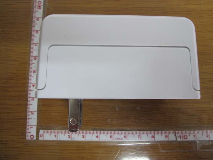
Click to zoom
Application Details
- Equipment Class
- DSS - Part 15 Spread Spectrum Transmitter
- Date of Grant
- Aug 17, 2010
- Application Purpose
- Original Equipment
- Date of Application
- Aug 16, 2010
- Equipment Note
- HOME ENERGY GATEWAY
- Frequency Range
- 2405.00000000 - 2470.00000000
- Company
- eZEX Corporation
- Country
- South Korea
Documents & Files
Document Text
Text extracted from the exhibit documents filed with the FCC. Open a document above to read the original.
Users Manual
Home Energy Gateway Use & Care Manual Table of Contents Chapter 1, 2, etc. Product Overview Thank you for purchasing the GE Home Energy Gateway. This device is designed to help you manage your home energy consumption and cost. The HEG will help you shift energy intensive tasks from high cost periods to lower cost periods of the day. Changing your energy usage to take advantage of variable pricing and adjusting your thermostat settings can have an impact on your energy bill and carbon footprint. Note: In order to monitor the energy use of your appliances, the appliances must be demand response enabled and must be equipped with the appropriate Zigbee communications module. Please consult your appliance owner’s manual for more details. Box Contents This section will contain a picture of everything that comes in the box. Below is initial list. • Home Energy Gateway. • Ethernet cable. • Installation CD. • Quick start guide. System View Manual will contain a picture of the HEG with arrows & text for the Leds, reset button, Ethernet port. A description of each should then be given below. • AC plug. Provides power the HEG. • Ethernet port for connecting to an existing Ethernet network. • Reset button. This button is used to cycle power on the HEG and also reset the HEG to its factory default settings. • LED indicators. These indicators are used to represent system status and will provide system diagnostics in the event of a failure. System Requirements In order to install the Home Energy Gateway, you must have the following: Operating System requirements: Mac OS X version 10.4.1 or later, Windows 7, Windows Vista SPX, or Windows XP SPX. Internet Browser requirements • Internet Explorer 8 or higher • Chrome 4 • Safari 4 • Mozilla Firefox 3 • Opera 10 Software requirements: • Adobe Air version 2.0 Beta Wireless Network requirements: • In order to access the HEG via wireless network, the computer must have a compatible 801.11a, 801.11b, or 801.11g wireless adapter. Recording Your Home Energy Gateway Product Information In the following table, please fill in all the required information of your device. This information can be found on the label on the bottom side of the device. Also, please record the purchase date and any other notes such as your operating system and software versions. This information will be necessary for setup and technical support. Serial Number: Model Number: MAC Address: Installation Code: Purchase Date: System Notes (passwords/software revs/etc): Home Energy Gateway installation During installation, the setup software will install the HEG client application on your computer. This program will allow you to configure your HEG network (add/remove devices) and then view your total energy consumption. To install the Home Energy Gateway: • Insert the CD into your computer’s CD-ROM drive. • Click “Setup Home Energy Gateway”. If you do not see this screen, access the setup CD directly. To do so, perform the following steps for your specific operating system. o Windows 7. o Go to Start -> Computer. Double click your cd-rom drive. o Windows Vista. o Go to Start -> Computer. Double click your cd-rom drive. o Windows XP. o Go to Start -> My Computer and select your cd-rom drive. Double click on setup.exe. o Mac OS X. o Double click the cd on your desktop. Double-click on Setup. • Read the Software End User Agreement. To accept the agreement, and continue with the installation click Next. • Follow the steps as outlined in the installation CD (wizard). Appendix A: Safety Precautions When using this electrical device, basic safety precautions should be followed, including the following: • Use this device only for its intended purpose as described in this Owner’s Manual. • Read all the instructions before using this device. • This device is a high-voltage component and therefore should not be opened for any reason, even when the device is unplugged. • Never force a connector into the Ethernet port. If the connector does not attach with a reasonable amount of force, they do not match. Verify the connector matches the port and that it is orientated correctly. • During standard use of this device, it is normal for the case to get warm. The case functions as a cooling surface that transfers heat from inside the unit to the cooler air outside. How to connect electricity • This device is equipped with an integrated 3-prong (grounding) plug which mates with a standard 3-prong (grounding) wall outlet to minimize the possibility of an electric shock hazard. • The wall outlet and circuit should be checked by a qualified electrician to make sure the outlet is properly grounded. • If the outlet is a standard 2-prong wall outlet, it is the consumers responsibility and obligation to have it replaced with a properly grounded 3-prong wall outlet. • Operate this device only from the type of power indicated on the marking label. If you are note sure of the type of power available, consult your dealer or local power company. • The only way to turn off power to this device is to disconnect it from the power source. • When connecting or disconnection this device, always hold it by its sides. Keep fingers away from the metal part of the plug. Avoid wet locations. • Warning: To reduce the risk of electrical shock or injury, do not use this device in or near wet locations. • Keep this product away from all liquids. Other safety related tips. • Unplug the device from the wall outlet before cleaning. Do not use liquid cleaners or aerosol cleaners. Use a damp cloth for cleaning. • Warning: Do not attempt to open or disassemble this device. You run the risk of electric shock and voiding the limited warranty. No user-serviceable parts are located inside the device. Appendix A: Troubleshooting & Customer Support TBD Appendix B: Product Specifications TBD C: Warranty Information All warranty service provided by our Factory Service Centers, or an authorized Customer Care technician. To schedule service, visit us on-line a…
Text truncated - open the document above for the full version.
Cover Letter(s)
eZEX Corporation Rm 508, Ssangyong IT Twin-tower 2, 442-5, Sangdaewon-dong, Jungwon-gu, Seongnam-si, Gyeonggi-do, South Korea TEL No : +82-31 - 608 - 4700 FAX No : +82-31-608 - 4701 August 11, 2010 Federal Communications Commission Authorization and Evaluation Division 1435 Oakland Mills Road Columbia, MD 21046 In re : eZEX Corporation FCC Application for FCC ID: YI7HES10000R1W To Whom It May Concern: We, the undersigned, hereby attest to the fact that we will apply the Declaration of Conformity procedure to the class B computer peripheral portion of this composite filing. Regards, Sincerely, Suk Bum MOK Manager
Cover Letter(s)
eZEX Corporation Rm 508, Ssangyong IT Twin-tower 2, 442-5, Sangdaewon-dong, Jungwon-gu, Seongnam-si, Gyeonggi-do, South Korea TEL No : +82-31 - 608 - 4700 FAX No : +82-31-608 - 4701 August 6, 2010 Timco Engineering, Inc. 849 NW State Road 45 P.O.Box 370 Newberry,m Florida 32669 LETTER OF AUTHORIZATION To whom it may concern: We, the undersigned, hereby authorize LTA Co., Ltd., to act on our behalf in all manners relating to application for equipment authorization for FCC ID: YI7HES10000R1W . including signing of all documents relating to these matters. Any and all acts carried out by LTA Co., Ltd., on our behalf shall have the same affect as acts of our own. This authorization is valid until further written notice from eZEX Corporation LTA Co.,LTD. (Contact Person) Contact name: LEE, Kyung-Taek Position: Manager Phone:(82)31-323-6008 E-mail: [email protected] Sincerely, Suk Bum MOK Manager
Cover Letter(s)
eZEX Corporation Rm 508, Ssangyong IT Twin-tower 2, 442-5, Sangdaewon-dong, Jungwon-gu, Seongnam-si, Gyeonggi-do, South Korea TEL No : +82-31 - 608 - 4700 FAX No : +82-31-608 - 4701 August 6, 2010 Federal Communications Commission Equipment Authorization Branch 7435 Oakland Mills Road Columbia, MD 21046 In re : eZEX Corporation FCC ID: YI7HES10000R1W Request for Confidentiality Pursuant to Sections 0.457 and 0.459 of the Commission’s Rules (CFR 47), and Section 552 (b) (4) of the Freedom of Information Act, eZEX Corporation. hereby requests confidentiality and treatment of certain information accompanying this application. The materials contain trade secrets and proprietary information not customarily released to the public. The public disclosure of these matters might be harmful to the Applicant and provide unjustified benefits to its competitors. We are also hereby request Short-Term Confidentiality for 180 days after the grant as outlined in Public Notice DA 04-1705. This provision will give eZEX Corporation. temporary confidentiality of commercially sensitive information prior to product release. The requested Confidential and Temporary Confidential exhibits are listed as follows: Exhibit Type File Name Schematics CONF APPENDIX YI7HES10000R1W SCH DIA.pdf Parts list CONF APPENDIX YI7HES10000R1W PL.pdf Block diagram CONF APPENDIX YI7HES10000R1W BLK DIA.pdf CONFIDENTIAL Operational description CONF APPENDIX YI7HES10000R1W OpDes.pdf Internal Photos SHORT-TERM CONF YI7HES10000R1W INT Photo.pdf User’s Manual SHORT-TERM CONF YI7HES10000R1W Manual.pdf EXT Photo SHORT-TERM CONF YI7HES10000R1W EXT Photo.pdf SHORT-TERM CONFIDENTIAL Test Photo SHORT-TERM CONF YI7HES10000R1W Test Photo.pdf The Applicant understands that pursuant to Rule 0.457, disclosure of this application and all accompanying documentations, where applicable, will not be made public before the date of the Grant for this application. Sincerely, Suk Bum MOK Manager
External Photos
FCC ID: YI7HES10000R1W Copyright ○ c 2010, LTA Co., Ltd. Page 1 of 3 FCC ID: YI7HES10000R1W Copyright ○ c 2010, LTA Co., Ltd. Page 2 of 3 FCC ID: YI7HES10000R1W Copyright ○ c 2010, LTA Co., Ltd. Page 3 of 3
ID Label/Location Info
FCC ID: YI7HES10000R1W Copyright Ⓒ 2010, LTA Co., Ltd. SAMPLE LABEL & LOCATION FCC ID: YI7HES10000R1W M/N: HES1E000R0WW Made in Korea
Internal Photos
FCC ID: YI7HES10000R1W Copyright ○ c 2010LTA Co., Ltd. Page 1 of 6 Internal photo FCC ID: YI7HES10000R1W Copyright ○ c 2010LTA Co., Ltd. Page 2 of 6 Main Board –Front Main Board –Rear FCC ID: YI7HES10000R1W Copyright ○ c 2010LTA Co., Ltd. Page 3 of 6 SMPS-Front SMPS-Rear FCC ID: YI7HES10000R1W Copyright ○ c 2010LTA Co., Ltd. Page 4 of 6 LAN –Front LAN –Rear FCC ID: YI7HES10000R1W Copyright ○ c 2010LTA Co., Ltd. Page 5 of 6 Zigbee(SPI) Antenna Main Board –Front Side Zigbee(SPI) Antenna WLAN Antenna Zigbee(UART) Antenna FCC ID: YI7HES10000R1W Copyright ○ c 2010LTA Co., Ltd. Page 6 of 6 Zigbee(UART) Antenna WLAN Antenna
RF Exposure Info
FCC ID: YI7HES10000R1W ATTACHMENT ** MPE Calculations ** 802.11g The MPE calculation for this exposure is shown below. The peak radiated output power (EIRP) is calculated as follows: EIRP = P + G EIRP = 16.65dBm + 2dBi EIRP = 18.65 dBm Where, P = Power input to the antenna (mW) G = Power gain of the antenna (dBi) Power density at the specific separation: S = PG/(4R 2 π) S = (46.24 * 1.58) / (4 * 20 2 * π) S = 0.0146 mW/cm 2 Where, S = Maximum power density (mW/cm 2 ) P = Power input to the antenna (mW) G = Numeric power gain of the antenna R = Distance to the center of the radiation of the antenna (20cm = limit for MPE) The Maximum permissible exposure (MPE) for the general population is 1 mW/cm 2 . The power density does not exceed the 1 mW/cm 2 limit. Therefore, the exposure condition is compliant with FCC rules. Estimated safe separation: R = √(PG / 4π) R = √(46.24* 1.58 / 4π) R = 2.42Cm Where, P = Power input to the antenna (mW) G = Numeric power gain of the antenna R = Distance to the center of the radiation of the antenna (20cm = limit for MPE) The numeric gain(G) of the antenna with a gain specified in dB is determined by: G = Log -1 (dB antenna gain / 10) G = Log -1 (2 / 10) G = 1.58 FCC ID: YI7HES10000R1W ATTACHMENT ** MPE Calculations ** Zigbee-SPI The MPE calculation for this exposure is shown below. The peak radiated output power (EIRP) is calculated as follows: EIRP = P + G EIRP = 22.80dBm + 2dBi EIRP = 24.8 dBm Where, P = Power input to the antenna (mW) G = Power gain of the antenna (dBi) Power density at the specific separation: S = PG/(4R 2 π) S = (190.55 * 1.58) / (4 * 20 2 * π) S = 0.0601 mW/cm 2 Where, S = Maximum power density (mW/cm 2 ) P = Power input to the antenna (mW) G = Numeric power gain of the antenna R = Distance to the center of the radiation of the antenna (20cm = limit for MPE) The Maximum permissible exposure (MPE) for the general population is 1 mW/cm 2 . The power density does not exceed the 1 mW/cm 2 limit. Therefore, the exposure condition is compliant with FCC rules. Estimated safe separation: R = √(PG / 4π) R = √(190.55* 1.58 / 4π) R = 4.9Cm Where, P = Power input to the antenna (mW) G = Numeric power gain of the antenna R = Distance to the center of the radiation of the antenna (20cm = limit for MPE) The numeric gain(G) of the antenna with a gain specified in dB is determined by: G = Log -1 (dB antenna gain / 10) G = Log -1 (2 / 10) G = 1.58 FCC ID: YI7HES10000R1W ATTACHMENT ** MPE Calculations ** Zigbee-UART The MPE calculation for this exposure is shown below. The peak radiated output power (EIRP) is calculated as follows: EIRP = P + G EIRP = 21.41dBm + 2dBi EIRP = 23.41 dBm Where, P = Power input to the antenna (mW) G = Power gain of the antenna (dBi) Power density at the specific separation: S = PG/(4R 2 π) S = (138.36 * 1.58) / (4 * 20 2 * π) S = 0.0436 mW/cm 2 Where, S = Maximum power density (mW/cm 2 ) P = Power input to the antenna (mW) G = Numeric power gain of the antenna R = Distance to the center of the radiation of the antenna (20cm = limit for MPE) The Maximum permissible exposure (MPE) for the general population is 1 mW/cm 2 . The power density does not exceed the 1 mW/cm 2 limit. Therefore, the exposure condition is compliant with FCC rules. Estimated safe separation: R = √(PG / 4π) R = √(138.36* 1.58 / 4π) R = 4.18Cm Where, P = Power input to the antenna (mW) G = Numeric power gain of the antenna R = Distance to the center of the radiation of the antenna (20cm = limit for MPE) The numeric gain(G) of the antenna with a gain specified in dB is determined by: G = Log -1 (dB antenna gain / 10) G = Log -1 (2 / 10) G = 1.58
Test Report
Ref. No.: LR5001901008A Copyright ̺ c 2010, LTA Co., Ltd. Page 1 of 79G 243 Jubug-Ri,Yangji-Myeon, Yongin-Si, Gyeonggi-Do, Korea 449-822 Tel: +82-31-323-6008 Fax: +82-31-323-6010 http://www.ltalab.com G Dates of Tests : August 2~12, 2010 Test Report S/N: LR500191008A Test Site : LTA CO., LTD CERTIFICATION OF COMPLIANCE FCC ID. APPLICANT Equipment Class : Digital Transmission System (DTS) Manufacturing Description : Home Energy Gateway Manufacturer : eZEX Corporation Model name : HES1E000R0WW Variant Model name : HES1N000R0WW Test Device Serial No.: : Identical prototype Rule Part(s): FCC Part 15.247 Subpart C; ANSI C-63.4-2003 Frequency Range : 2412MHz ~ 2462MHz (802.11b/g) 2405MHz ~ 2480MHz (SPI interface) 2405MHz ~ 2470MHz (UART interface) Max. Output Power : Max 14.64dBm - Conducted (802.11b) Max 16.65dBm - Conducted (802.11g) Max 22.80dBm - Conducted (SPI interface) Max 21.41dBm - Conducted (UART interface) Data of issue : August 12, 2010 This test report is issued under the authority of: The test was supervised by: G G G G Kyung-Taek LEE, Technical Manager Hyun-Chae You, Test Engineer This test result only responds to the tested sample. It is not allowed to copy this report even partly without the allowance of the test laboratory. This report must not be used by the applicant to claim product endorsement by any agency. Ϳ·ͽͲ͑ͽͲͳ͑ʹΠΕΖͫ͑ͣͨͣͤ͟͡͡͞͡ YI7HES10000R1W eZEX Corporation Ref. No.: LR5001901008A Copyright ̺ c 2010, LTA Co., Ltd. Page 2 of 79G G G TABLE OF CONTENTS 1. GENERAL INFORMATION’S -------------------------------------------------------------------------- 2. INFORMATION’S ABOUT TEST ITEM ------------------------------------------------------------- 3. TEST REPORT --------------------------------------------------------------------------------------------- 3.1 SUMMARY OF TESTS ------------------------------------------------------------------------------ 3.2 TECHNICAL CHARACTERISTICS TEST(802.11b/g) ------------------------------------------ 3.2.1 6dB BANDWIDTH ------------------------------------------------------------------------------ 3.2.2 PEAK OUTPUT POWER ----------------------------------------------------------------------- 3.2.3 POWER SPECTRAL DENSITY --------------------------------------------------------------- 3.2.4 BAND – EDGE & SPURIOUS ----------------------------------------------------------------- 3.2.5 FIELD STRENGTH OF HARMONICS ------------------------------------------------------ 3.2.6 AC CONDUCTED EMISSIONS -------------------------------------------------------------- 3.3 TECHNICAL CHARACTERISTICS TEST(Zigbee for SPI/UART) --------------------------- 3.3.1 6dB BANDWIDTH ------------------------------------------------------------------------------ 3.3.2 PEAK OUTPUT POWER ----------------------------------------------------------------------- 3.3.3 POWER SPECTRAL DENSITY --------------------------------------------------------------- 3.3.4 BAND – EDGE & SPURIOUS ----------------------------------------------------------------- 3.3.5 FIELD STRENGTH OF HARMONICS ------------------------------------------------------ 3.3.6 AC CONDUCTED EMISSIONS -------------------------------------------------------------- G APPENDIX APPENDIX TEST EQUIPMENT USED FOR TESTS -------------------------------------------- 3 4 5 5 6 6 11 16 21 32 36 39 39 44 49 54 70 75 78 Ref. No.: LR5001901008A Copyright ̺ c 2010, LTA Co., Ltd. Page 3 of 79G 1. General information’s 1-1 Test Performed Company name : LTA Co., Ltd. Address : 243, Jubug-ri,Yangji-Myeon,Youngin-Si, Kyunggi-Do, Korea. 449-822 Web site : http://www.ltalab.com E-mail : [email protected] Telephone : +82-31-323-6008 Facsimile +82-31-323-6010 Quality control in the testing laboratory is implemented as per ISO/IEC 17025 which is the “General requirements for the competents of calibration and testing laboratory”. 1-2 Accredited agencies LTA Co., Ltd. is approved to perform EMC testing by the following agencies: AgencyCountryAccreditation No. ValidityReference NVLAP U.S.A 200723-0 2010-09-30 ECT accredited Lab. RRL KOREA KR0049 2011-06-20 EMC accredited Lab. FCC U.S.A 610755 2011-04-22 FCC filing VCCI JAPAN R2133, C2307 2011-06-21 VCCI registration IC CANADA IC5799 2012-05-14 IC filing Ref. No.: LR5001901008A Copyright ̺ c 2010, LTA Co., Ltd. Page 4 of 79G 2. Information’s about test item 2-1 Applicant & Manufacturer Company name : eZEX Corporation Address : Rm 508, Ssangyong IT Twin-tower 2, 442-5, Sangdaewon-dong, Jungwon-gu, Seongnam-si, Gyeonggi-do, South Korea Tel / Fax : TEL No : +82-31 - 608 - 4700 FAX No : +82-31-608 - 4701 2-2 Equipment Under Test (EUT) Trade name : Home Energy Gateway FCC ID : YI7HES10000R1W Model name : HES1E000R0WW Variant Model name : HES1N000R0WW Serial number : Identical prototype Date of receipt : August 2, 2010 EUT condition : Pre-production, not damaged Antenna type : Chip antenna with Max. 2.0 dBi gain Frequency Range : 2412MHz ~ 2462MHz (802.11b/g) 2405MHz ~ 2480MHz (SPI interface) 2405MHz ~ 2470MHz (UART interface) RF output power : Max 14.64dBm - Conducted (802.11b) Max 16.65dBm - Conducted (802.11g) Max 22.80dBm - Conducted (SPI interface) Max 21.41dBm - Conducted (UART interface) Number of channels : 802.11b/g for 11 and SPI for 16 and UART for 14 Type of Modulation : CCK, DQPSK, DBPSK for DSSS 64QAM, 16QAM, QPSK, BPSK for OFDM O-QPSK for Zigbee Transfer Rate : 11/5.5/2/1Mbps for 802.11b 54/48/36/24/18/12/9/6Mbps for 802.11g Power Source : 120VAC G 2-3 Tested frequency LOWMIDHIGH Frequency (MHz) for 802.11b/g 2412 2437 2462 Frequency (MHz) for Zigbee(SPI) 2405 2440 2480 Frequency (MHz) for Zigbee(UART) 2405 2440 2470 2-4 Ancillary Equipment EquipmentModel No. Serial No. Manufacturer Notebook SFM-3200LW N/A Samsung Ref. No.: LR5001901008A Copyright ̺ c 2010, LTA Co., Ltd. Page 5 of 79G 3. Test Report 3.1 Summary of tests FCC Part Section(s) Parameter Limit Test Conditio n Status (note 1) 15.247(a) 6 dB Bandwidth > 500kHz C 15.247(b) Transmitter Peak Output Power < 1Watt C 15.247…
Text truncated - open the document above for the full version.
Test Setup Photos
FCC ID: YI7HES10000R1W Copyright ○ c 2010, LTA Co., Ltd. Page 1 of 2 Radiated Emission FCC ID: YI7HES10000R1W Copyright ○ c 2010, LTA Co., Ltd. Page 2 of 2 Conducted Emission
Contact Information
Applicant
Suk-Bom Mok
Test Firm
LTA Co.,LtdAhn Chulho
Technical Specifications
| # | Rule Parts | Frequency Range | Power Output |
|---|---|---|---|
| 4 | 15C | 2.40 GHz - 2.47 GHz | 140.00 mW |
Other Applications from eZEX Corporation
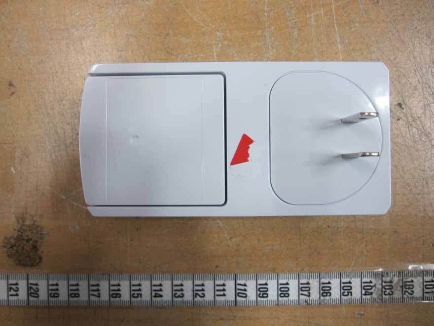
YI7HES2E4A0T
Oct 14, 2012HOME ENERGY GATEWAY
Equipment Class
DTS - Digital Transmission System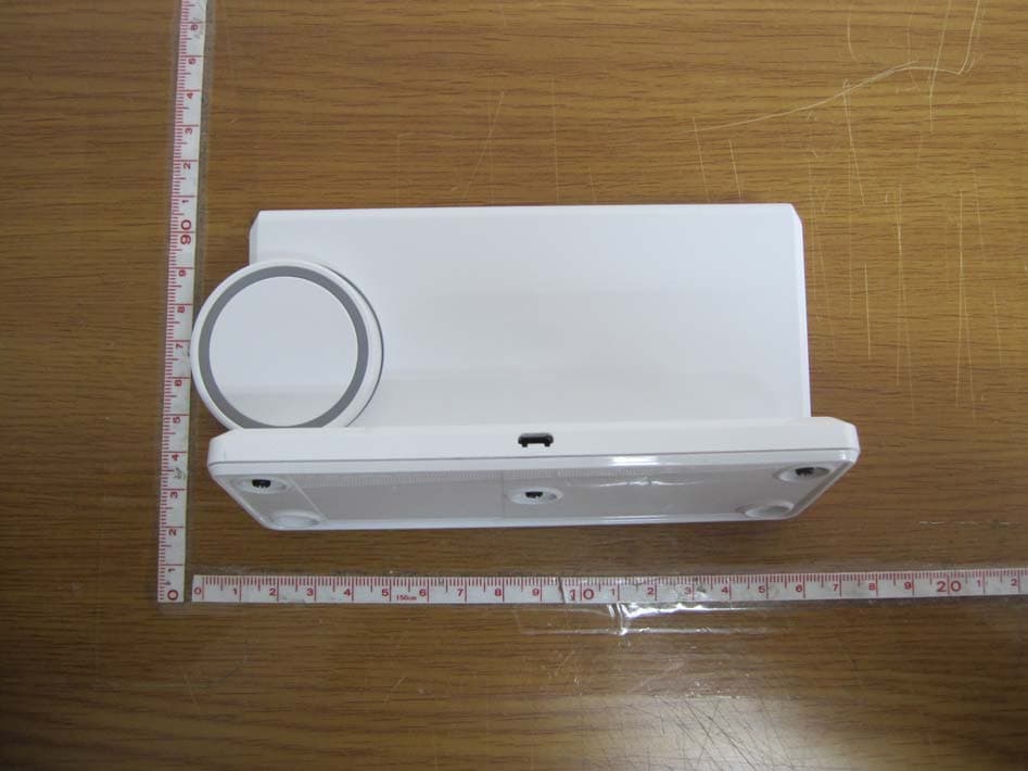
YI7IHD2E100T0W
Jan 27, 2011Color In-home Display
Equipment Class
DSS - Part 15 Spread Spectrum Transmitter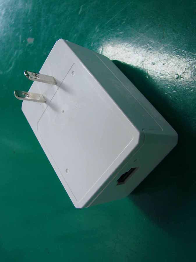
YI7HES1N00R0WW
Jul 20, 2010Home Energy Gateway
Equipment Class
DTS - Digital Transmission System