YIKMIION2Mother Board
Shenzhen Jehe Technology Development Co.,Ltd.
Click to zoom
Application Details
- Equipment Class
- JBC - Part 15 Class B Computing Device/Personal Computer
- Date of Grant
- Nov 03, 2010
- Application Purpose
- Original Equipment
- Date of Application
- Nov 02, 2010
- Equipment Note
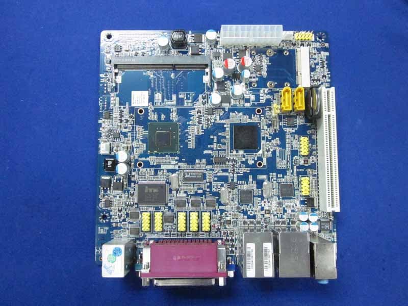
- Mother Board
- Country
- China
Documents & Files
Document Text
Text extracted from the exhibit documents filed with the FCC. Open a document above to read the original.
Users Manual
www.giadatech.com User’s Manual MI-ION2 All right reserved Motherboard Version 001 (2) this device must accept any interference received, including interference that may cause undesired operation. FCC ID:YIKMIION2 This device complies with Part 15 of the FCC Rules. Operation is subject to the following two conditions: (1) this device may not cause harmful interference, and 21 Gratitude ....................................................................................... I. About the product ........................................................................ 1. Picture of the motherboard ...................................................... 2. Features .............................................................................. 2.1 Processor ........................................................................ 2.2 Memory ........................................................................... 2.3 BIOS .............................................................................. 2.4 Interfaces of peripherals ...................................................... 2.5 Power management............................................................ 2.6 Expansion slot .................................................................. II. Hardware installation..................................................................... 1. Layout of motherboard ............................................................ 2. Installing memory .................................................................. 3. Install expansion slot card......................................................... 4. Motherboard jumper setting ...................................................... 4.1 SATA1/SATA2 (Serial ATA flat-cable sockets) ........................... 4.2 CPU_FAN1 (CPU FAN socket) ............................................. 4.3 CLR_CMOS(CMOS pin) ...................................................... 4.4 F_USB1/ F_USB2 (frond-end USB pin) ................................. 4.5 F_ AUDIO(Pins for front-end audio adapter) ........................... 4.6 ATX 12V (12V Power receptacle) .......................................... 4.7 F_ PANEL (Front-end control panel) ....................................... 5. Rear panel interface ............................................................... Contents III. BIOS setting .............................................................................. 1. Main menu ........................................................................... 2. Main (standard CMOS setup) ................................................... 3. Advanced (Advanced BIOS setup) ............................................. 4. Boot Configuration .................................................................. 5. Security Setup ........................................................................ 6. Exit ....................................................................................... IV. Software installation ..................................................................... 1. Install driver for motherboard ................................................... 1.1 Install driver for chipset ...................................................... 1.2 Install sound card driver ...................................................... 1.3 Install driver for on-board LAN chip ....................................... 1.4 Install driver for graphic card ................................................ 2. HD_AUDIO and sound card setup ............................................. 3 4 5 5 5 5 5 5 6 7 8 9 10 9 11 11 12 13 14 14 15 4 5 16 18 19 20 20 22 24 25 25 27 28 29 30 30 www.giadatech.com 4 3 GratitudeI. About the product 1. Picture of the motherboard NOTE: This is Giada real product photo show for your reference only, Product appearance depends on goods. Thank you for choosing Giada motherboard. Giada MI-ION2 is based on Intel® Atom™ Processor and NM10 chipset, with Next Generation NVIDIA® ION™ GPU. It supports DDR2 667/800 Dual-channel memory, on-board HD-AUDIO sound card and gigabit LAN. Support HDMI display output. Any question about the product, please send e-mail to our support center. Headquarter: [email protected] [email protected] USA office: [email protected] www.giadatech.com 6 5 2.1 Processor · · 2.2 Memory · · 2.3 BIOS · · · · 2.4 Interfaces for peripherals · · · · · · · · · 2.5 Power management · · 2.6 Expansion slot · 2. Features On-board Intel® Atom™ Processor D525; 2. On-board Next Generation NVIDIA® ION™ GPU, 512MB VRAM. Supports 200-Pin DDR2 800/667/533MHz memories * 2; 4GB at maximum; (2GB/per slot). Supports PNP, APM and ATAPI; Supports ACPI and DMI; Automatic detection and supporting hard disk whose LBA mode is over 160G; End-users can easily upgrade the motherboard with BIOS. Two SATA2 HDD port; One HDMI digital interface; One DVI interface; Six high-speed transmission ports (max. 480Mb/s) which support USB2.0 and are compatible with USB1.1; One RJ45 network interface (PCIe Gigabit Ethernet); On-board HD-AUDIO audio adapter; Interfaces on panels can be compatible with HDD LED, Speaker, etc; One CMOS contact pin; One system FAN socket. Support APM and ACPI; Compatible with energy star “Green PC”. Two MINI-PCIe slot. Warning · · · · · The motherboard consists of a great number of ICs and other components. These ICs might be damaged by the static charge. Therefore, the user must make the following preparations before installation: Turn off the power of the computer. It is preferable the power cord be unplugged. Take care not to contact the metal wires and theirs joints on the motherboard when handling it. It is preferable that the operator wear the anti-static wrist strap when handling the IC components. Before the ICs are installed, the components of the motherboard should be placed on the anti-static mat or bag. When you remove the plug on the ATX power supply of the motherboard, make sure the switch of the power supply is in OFF state. Instal…
Text truncated - open the document above for the full version.
External Photos
R AUDIX Technology (Shenzhen) Co., Ltd. FCC ID:YIKMIION2 page Audix Technology (Shenzhen) Co., Ltd. Report No. ACS-F10297 7-1 7. PHOTOGRAPH OF EUT Figure 1 Frontside of the Motherboard Figure 2 Backside of the Motherboard R AUDIX Technology (Shenzhen) Co., Ltd. FCC ID:YIKMIION2 page Audix Technology (Shenzhen) Co., Ltd. Report No. ACS-F10297 7-2 Figure 3 I/O Port of the Motherboard
Internal Photos
R AUDIX Technology (Shenzhen) Co., Ltd. FCC ID:YIKMIION2 page Audix Technology (Shenzhen) Co., Ltd. Report No. ACS-F10297 7-1 7. PHOTOGRAPH OF EUT Figure 1 Frontside of the Motherboard Figure 2 Backside of the Motherboard R AUDIX Technology (Shenzhen) Co., Ltd. FCC ID:YIKMIION2 page Audix Technology (Shenzhen) Co., Ltd. Report No. ACS-F10297 7-2 Figure 3 I/O Port of the Motherboard
Test Report
R AUDIX Technology (Shenzhen) Co., Ltd. FCC ID:YIKMIION2 Audix Technology (Shenzhen) Co., Ltd. Report No. ACS-F10297 APPLICATION FOR CERTIFICATION On Behalf of SHENZHEN JIEHE TECHNOLOGY DEVELOPMENT Co., Ltd Mother Board Model Number: Giada MI-ION2 FCC ID: YIKMIION2 Prepared for : SHENZHEN JIEHE TECHNOLOGY DEVELOPMENT Co., Ltd 2/F, Block A, Tsinghua Information Harbor, North Section, Shenzhen Hi-tech Park, Nanshan District, Shenzhen, China P. R Prepared By : Audix Technology (Shenzhen) Co., Ltd. No. 6, Ke Feng Rd., 52 Block, Shenzhen Science & Industrial Park, Nantou, Shenzhen, Guangdong, China Tel: (0755) 26639496 Report Number : ACS-F10297 Date of Test : Oct.14~21, 2010 Date of Report : Oct.22, 2010 R AUDIX Technology (Shenzhen) Co., Ltd. FCC ID:YIKMIION2 Audix Technology (Shenzhen) Co., Ltd. Report No. ACS-F10297 TABLE OF CONTENTS Description Page 1. SUMMARY OF STANDARDS AND RESULTS .................................................................. 1-1 1.1. Description of Standards and Results ............................................................................................. 1-1 2. GENERAL INFORMATION .................................................................................................. 2-1 2.1. Description of Device (EUT) ......................................................................................................... 2-1 2.2. Test configuration with EUT ......................................................................................................... 2-1 2.3. Tested Supporting System Details ................................................................................................. 2-2 2.4. Block Diagram of connection between EUT and simulators ......................................................... 2-3 2.5. Test Facility .................................................................................................................................... 2-4 2.6. Test Uncertainty (95% confidence levels, k=2) ............................................................................. 2-4 3. POWER LINE CONDUCTED EMISSION TEST ................................................................ 3-1 3.1. Test Equipments ............................................................................................................................. 3-1 3.2. Block Diagram of Test Setup ......................................................................................................... 3-1 3.3. Power Line Conducted Emission Test Limits ................................................................................ 3-1 3.4. Configuration of EUT on Test ....................................................................................................... 3-2 3.5. Operating Condition of EUT .......................................................................................................... 3-2 3.6. Test Procedure ................................................................................................................................ 3-2 3.7. Power Line Conducted Emission Test Results............................................................................... 3-3 4. RADIATED EMISSION TEST ............................................................................................... 4-1 4.1. Test Equipment .............................................................................................................................. 4-1 4.2. Block Diagram of Test Setup ......................................................................................................... 4-2 4.3. Radiated Emission Limit ................................................................................................................ 4-3 4.4. EUT Configuration on Test ............................................................................................................ 4-3 4.5. Operating Condition of EUT .......................................................................................................... 4-3 4.6. Test Procedure ................................................................................................................................ 4-3 4.7. Radiated Emission Test Results ..................................................................................................... 4-4 5. DEVIATION TO TEST SPECIFICATIONS ........................................................................ 5-1 6. PHOTOGRAPH OF TEST ...................................................................................................... 6-1 6.1. Photos of Power Line Conducted Emission Test ........................................................................... 6-1 6.2. Photos of Radiated Emission Test for 30~1000MHz ..................................................................... 6-2 6.3. Photos of Radiated Emission Test for above 1GHz ..................................................................... 6-10 7. PHOTOGRAPH OF EUT ........................................................................................................ 7-1 R AUDIX Technology (Shenzhen) Co., Ltd. FCC ID:YIKMIION2 Page Audix Technology (Shenzhen) Co., Ltd. Report No. ACS-F10297 1-1 1. SUMMARY OF STANDARDS AND RESULTS 1.1. Description of Standards and Results The EUT have been tested according to the applicable standards as referenced below. EMISSION Description of Test Item Standard Limits Results Power Line Conducted Emission Test FCC Part 15: 2008 ANSI C63.4: 2009 Class B PASS Radiated Emission Test FCC Part 15: 2008 ANSI C63.4: 2009 Class B PASS R AUDIX Technology (Shenzhen) Co., Ltd. FCC ID:YIKMIION2 Page Audix Technology (Shenzhen) Co., Ltd. Report No. ACS-F10297 2-1 2. GENERAL INFORMATION 2.1. Description of Device (EUT) Product name : Mother Board (Note) Model Number : Giada MI-ION2 FCC ID : YIKMIION2 Highest clock frequency : 1800MHz Applicant : SHENZHEN JIEHE TECHNOLOGY DEVELOPMENT Co., Ltd 2/F, Block A, Tsinghua Information Harbor, North Section, Shenz…
Text truncated - open the document above for the full version.
Test Setup Photos
R AUDIX Technology (Shenzhen) Co., Ltd. FCC ID:YIKMIION2 Page 6-1 Audix Technology (Shenzhen) Co., Ltd. Report No. ACS-F10297 6. PHOTOGRAPH OF TEST 6.1. Photos of Power Line Conducted Emission Test R AUDIX Technology (Shenzhen) Co., Ltd. FCC ID:YIKMIION2 Page 6-2 Audix Technology (Shenzhen) Co., Ltd. Report No. ACS-F10297 6.2. Photos of Radiated Emission Test for 30~1000MHz Lie Low With cover R AUDIX Technology (Shenzhen) Co., Ltd. FCC ID:YIKMIION2 Page 6-3 Audix Technology (Shenzhen) Co., Ltd. Report No. ACS-F10297 R AUDIX Technology (Shenzhen) Co., Ltd. FCC ID:YIKMIION2 Page 6-4 Audix Technology (Shenzhen) Co., Ltd. Report No. ACS-F10297 Lie Low Without cover R AUDIX Technology (Shenzhen) Co., Ltd. FCC ID:YIKMIION2 Page 6-5 Audix Technology (Shenzhen) Co., Ltd. Report No. ACS-F10297 R AUDIX Technology (Shenzhen) Co., Ltd. FCC ID:YIKMIION2 Page 6-6 Audix Technology (Shenzhen) Co., Ltd. Report No. ACS-F10297 Stand Up With cover R AUDIX Technology (Shenzhen) Co., Ltd. FCC ID:YIKMIION2 Page 6-7 Audix Technology (Shenzhen) Co., Ltd. Report No. ACS-F10297 R AUDIX Technology (Shenzhen) Co., Ltd. FCC ID:YIKMIION2 Page 6-8 Audix Technology (Shenzhen) Co., Ltd. Report No. ACS-F10297 Stand Up Without cover R AUDIX Technology (Shenzhen) Co., Ltd. FCC ID:YIKMIION2 Page 6-9 Audix Technology (Shenzhen) Co., Ltd. Report No. ACS-F10297 R AUDIX Technology (Shenzhen) Co., Ltd. FCC ID:YIKMIION2 Page 6-10 Audix Technology (Shenzhen) Co., Ltd. Report No. ACS-F10297 6.3. Photos of Radiated Emission Test for above 1GHz Lie Low With cover Lie Low Without cover R AUDIX Technology (Shenzhen) Co., Ltd. FCC ID:YIKMIION2 Page 6-11 Audix Technology (Shenzhen) Co., Ltd. Report No. ACS-F10297 Stand up With cover Stand up Without cover
Contact Information
Applicant
Barry Cheung(Product Manager)
Technical Contact
AUDIX Technology (Shenzhen) Co., Ltd.Lu Ken
[email protected]86-755-26639497
52 Block Shenzhen Science&Industry · Shenzhen · China
Test Firm
Audix Technology (Shenzhen) Co.Smart Tsai
Technical Specifications
| # | Rule Parts | Frequency Range | Power Output |
|---|---|---|---|
| 1 | 15B | - | - |
Other Applications from Shenzhen Jehe Technology Development Co.,Ltd.
YIKMID525
Dec 15, 2010Mother Board
Equipment Class
JBC - Part 15 Class B Computing Device/Personal Computer
YIKD2301
Dec 08, 2010Mini PC
Equipment Class
JBC - Part 15 Class B Computing Device/Personal Computer
YIKI30
Aug 18, 2010Mini PC
Equipment Class
DTS - Digital Transmission System
YIKI20PD
Aug 17, 2010Mini PC
Equipment Class
JBC - Part 15 Class B Computing Device/Personal Computer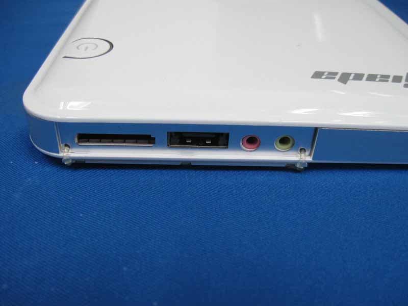
YIKN20
Aug 15, 2010Mini PC
Equipment Class
JBC - Part 15 Class B Computing Device/Personal Computer