YJC-MESHERT006Single Board Radio Module
AMI Investments, LLC d.b.a. Nighthawk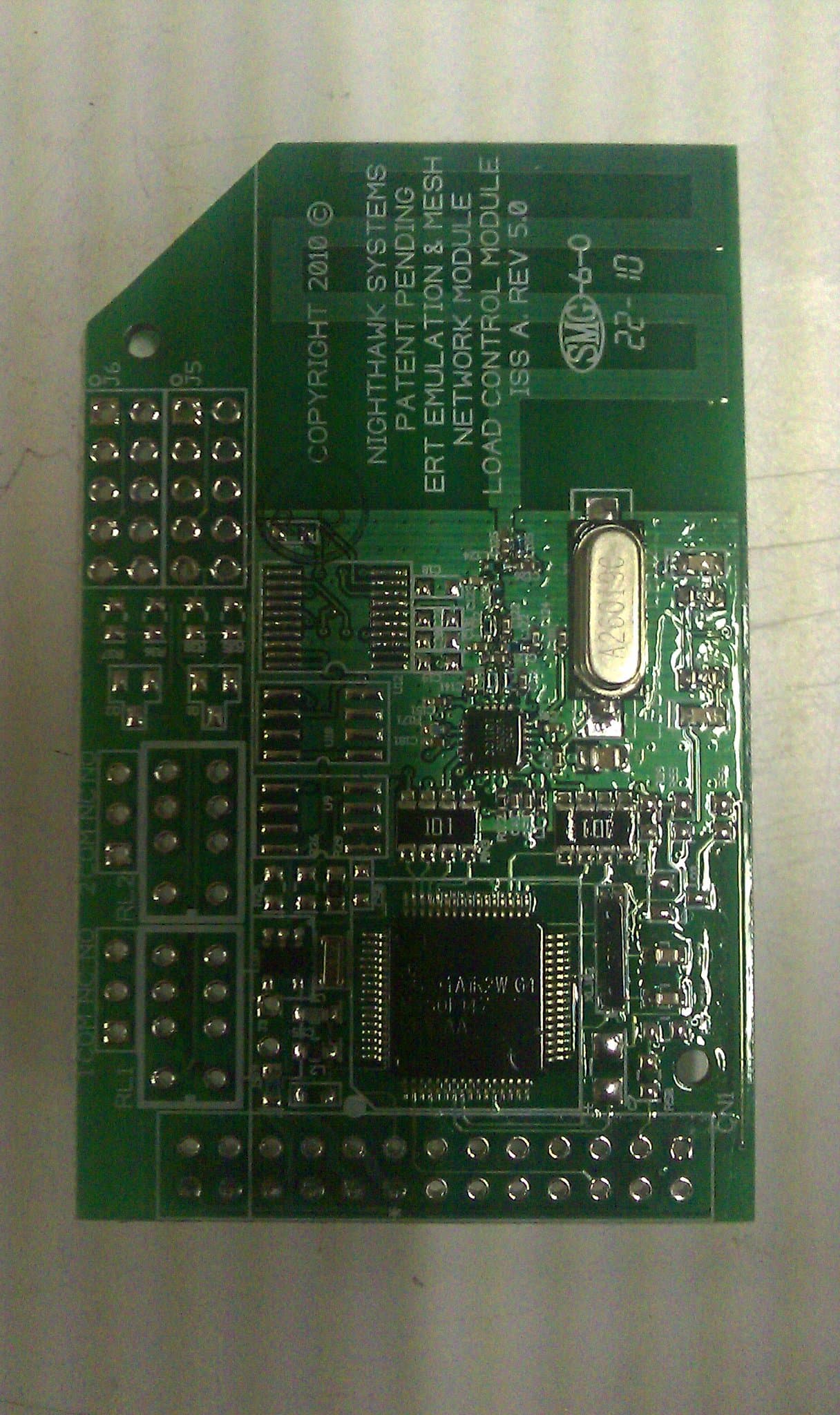
Click to zoom
Application Details
- Equipment Class
- DSS - Part 15 Spread Spectrum Transmitter
- Date of Grant
- Jul 14, 2010
- Application Purpose
- Original Equipment
- Date of Application
- Jul 13, 2010
- Equipment Note
- Single Board Radio Module
- Frequency Range
- 903.00000000 - 920.00000000
- Country
- United States
Documents & Files
Document Text
Text extracted from the exhibit documents filed with the FCC. Open a document above to read the original.
Users Manual
NIGHTHAWK Installation Instructions For the Model: MeshERT 006 FCC ID: YJC‐MESHERT006 Single Board Radio Module Notice: • This equipment complies with Part 15 of the FCC rules. Any changes or modifications not expressly approved by the manufacturer could void the user's authority to operate the equipment. • This device complies with Part 15 of the FCC rules subject to the following two conditions: 1) This device may not cause harmful interference 2) This device must accept all interference received, including interference that may cause undesired operation. This device must not be co‐located or operating in conjunction with any other antenna or transmitter in its final installation Limited Module Operational Description The Nighthawk Model MeshERT 006 Module is designed to provide supplemental drive by read capabilities to the standard Nighthawk RDM‐950 cell technology based electric meters, the CEO‐950 cell technology based disconnect collars for electric meters, and to serve as a data collector, radio repeater, and load control end point radio. It consists of a conformal coated single PCB with and integrated PCB antenna. It is designed to be powered through a connection to a Host board. The Host board provides and receives data from the Host board, but controls all radio functions and communications autonomously. To Install the MeshERT 006 Module in Nighthawk devices: 1) Locate the host board expansion header on the Nighthawk product board that the MeshERT 006 Module is being installed on. The expansion header will be a 2 X 13 (26 pin berg style header) The Host board expansion header on all Nighthawk products looks like this: 2) The Connector on the MeshERT 006 Module is a six pin male berg connector mounted on the bottom edge of the board. It looks like this: The MeshERT 006 Module is installed on the host board on the side that the expansion header has the label “ERT BOARD” in the bottom left. The MeshERT 006 Module is positioned so that the six pins on the bottom of the module line up with the blocked area of the host expansion connector. 3) The joined assembly will look like this: The MeshERT 006 Module is supplied the following from the Nighthawk Host board: 1) Power ‐ filtered and regulated 3.3 volt DC up to 250 milliamps. Ground for the module is shared with the Host board. 2) Serial communications is provided and controlled by the Host board and is typically 19200 baud half duplex TTL level signals. 3) Data and select lines are supplied at a 3.3 VDC level All operational commands to the MeshERT 006 Module are handled by the host board firmware and is all automatic. There are no direct user commands used with the MeshERT 006 Module. The MeshERT 006 Module controls all of the radio functions and RF transmissions. The Host board has no control over the radio functions; it simply supplies the module with data from the meter assembly. A label will be affixed to the Nighthawk product which states "Contains FCC ID: YJC‐ MESHERT006". The MeshERT 006 board will only be installed in Nighthawk products and Nighthawk retains responsibility for compliance of the final product.
Cover Letter(s)
Nighthawk June 22, 2010 6116 N. Central Expressway Suite 710 Dallas, TX 75206 Phone: 214 234 – 7571 http://www.nighthawkcontrol.com Request for Limited Modular Approval for the MeshERT 006 FCC ID: YJC-MESHERT006 Single Board Radio Module Nighthawk respectfully request Limited Modular Approval for the MeshERT 006 Single Board Radio Module, herein after referred to as “MeshERT”, based on the following features of compliance and tested criteria: 1. Shielding: The MeshERT PCB does not have its own shielding. 2. Buffered Inputs: The Host board that the MeshERT board is attached to provides and receives data from MeshERT board, but all MeshERT radio functions and RF communications are handled by the MeshERT board microcontroller autonomously. Serial communications are exchanged between Host board and the MeshERT board microcontroller to provide data for the MeshERT board to process, not control the Radio functions. The digital section is not surrounded or placed over grounding planes to reduce interjected noise switching noise in the RF circuits. Isolation resistors are employed to de‐couple digital noise from the processor and prevent it from reaching the RF chip. Inductors and filter capacitors filter any remaining noise from the 3.3 VDC power at the processor and RF chip power supply pins. 3. Power Regulation: Power supplied to the MeshERT board by a host board via the interface connector at a specified regulated 3.3 volt DC up to 250 milliamps. A zener diode on the MeshERT board power input buss insures that the voltage supplied cannot exceed 3.3 volts DC with respect to ground. Ballast resistors are used in series with the supply voltage to the processor and the RF chip to prevent current from exceeding specified levels. The microcontroller firmware controls the RF power output of the RF chip, and the microcontroller is controlled by a supervisory chip that prevents it from operating during under voltage and over voltage conditions by controlling the microcontroller’s reset pin. 4. Antenna Requirements: The MeshERT board employs a balun connected PCB folded monopole ¼ wave antenna and no other means of connecting an external antenna are provided. 5. Stand Alone Testing: The MeshERT board device was tested stand alone in accordance with the requirements of Part 15 including section 15.207. Please refer to Nemko Laboratories Report 49909RUS1 attached to this filing for testing results that substantiate this compliance. 6. Labeling: In the silk screening on the top of the MeshERT PCB has the following labeling: NIGHTHAWK Model: MeshERT 006 FCC ID: YJC‐MESHERT006 Documentation for the MeshERT board contains notations of the Model and FCC ID as well as the required Part 15 labeling since the board itself is too small to adequately support the full text. Users and installers of the module will receive these notices in writing with the equipment containing the MeshERT board Module. Examples of this can be found in the User guide and technical description document included with this filing. 7. Operating Requirements: Since the Microcontroller on the MeshERT board controls all of the radio functions there is no direct external access to the RF chip control lines. The module has been tested to assure compliance with the timing and field strength requirements for frequency hopping spread spectrum devices. Direct on board control of these timing requirements insures compliance. The MeshERT board will only work as a slave module to a host board. Software in the host board must be compatible with the MeshERT control commands. The entire system is designed for utility metering that operates autonomously without any direct user intervention and as such, is not subject to user control or input. No direct user interface and fully tested control software insures compliance with operational timing and field strength requirements. 8. RF Exposure: Due to the low power levels and the targeted applications of the MeshERT module for use in utility metering equipment operates out of doors unmanned, there is no occurrence of RF exposure in normal operating circumstances. The applications of the MeshERT module by the nature of its design and communications protocols ensure that it only has industrial applications and will be installed, maintained, and operated by trained professional personnel. Summation It is hoped that all requirements and expectations have been met and fulfilled by the previous explanations and descriptions. The MeshERT 006 board will only be installed in Nighthawk products and Nighthawk retains responsibility for compliance of the final product. All due diligence, research, and testing have been employed to assure that the device presented for Limited Modular Approval, the MeshERT 006 board, meets all of the requirements of the FCC and is hereby granted Limited Modular Approval. Respectfully submitted, New products Engineer Nighthawk Control Division [email protected]
Operational Description
NIGHTHAWK Technical Description Model: MeshERT 006 FCC ID: YJC‐MESHERT 006 Single Board Radi o Module Module Operational Description The Nighthawk Model MeshERT 006 Module is designed to provide supplemental drive by read capabilities to the standard Nighthawk RDM‐950 cell technology based electric meters, the CEO‐950 cell technology based disconnect collars for electric meters, and to serve as a dat a collector, radio repeater, and load control end point radio. It consists of a conformal coated single PCB with and integrated PCB antenna. It is designed to be powered through a connection to a Host board. The Host board provides and receives data fr om the Host board, but controls all radio functions and communications autonomously. It operates in two modes: 1) A 915 MHz band Frequency Hopping Spread Spectrum Transmit only mode designed to be compatible with the Itron® ERT reading system. It is capable of transmitting a standard consumption message (SCM) that can be read by a util ity’s existing meter reading equipment. 2) A 915 MHz band Frequency Hopping Spread Spectrum Transceiver that operates as an addressed mesh network radio. Each radio has a unique identification number (ID) that is used as the modules address. The module will also listen and keep a record of all of the surrou nding ID’s that it can receive and use those IDs to create a network path to route messages that it receives on to the intended module based on ID number hierarchy scheme. Messages are relayed in packets with routing information embedded in each packet. Data contai ned in each packet can be of any nature or purpose. The entire mesh system design is for low priority information that is compatible with a long latency network. Since the MeshERT 006 Module is designed to operate only with or in conjunction with other Nighthawk equipment, it uses a propri etary unique control and power interface to connect to a control and power source. The interface connector meets the following criteria: 1) Power is supplied from the Host board and is a filtered and regulated 3.3 volt DC up to 250 milliamps. Ground for the module is shared with the Host board. 2) Serial communications is host ed by the Host board and is typically 19200 baud half duplex TTL level signals. 3) Data and select lines are 3.3 VDC level PCB Design and Construction The MeshERT 006 Module is comprised of a Texas Instrument MSP430 microcontroller connected to a Texas Instruments CC1101 RF transceiver chip. The design employs a balun connected PCB folded monopole ¼ wave antenna. The antenna exhibits an average ‐3 dB loss from 902 to 928 MHZ. All digital and RF components are on the same side of the PCB and share a common ground with the host board interface connector located at the opposite end of the PCB from the antenna. The PCB is a four layer FR4 board with ground planes on each layer. Grounding is reinforced with a large number of vias connecting all of the grounding copper throughout the board. The digital section is not surrounded or placed over grounding planes to reduce interjected noise switching noise in the RF circuits. Isolation resistors are employed to de‐couple digital noise from the processor and prevent it from reaching the RF chip. Inductors and filter capacitors filter any remaining noise from the 3.3 VDC power at the processor and RF chip power supply pins. Typical Data: Meter ID ERT ID Cell Phone ID Meter Address Account Numbers Longitude & Latitude Meter Reading Meter Factor Meter Units Meter Rate Meter Errors Meter Tamper Flags Meter Mode Meter Status
Test Report
Nemko USA, Inc. FCC PART 15, SUBPART C FREQUENCY HOPPING SPREAD SPECTRUM TRANSMITTER EQUIPMENT: MeshERT006 PROJECT NO.:49909RUS1 Page 1 of 33 Nemko Test Report: 49909RUS1 Applicant: Nighthawk Systems 6116 North Central Expressway Suite 710 Dallas, TX 75206 Equipment Under Test: MeshERT 006 (E.U.T.) FCC ID: YJC-MESHERT006 In Accordance With: FCC Part 15, Subpart C, 15.247 Frequency Hopping Transmitters Tested By: Nemko USA Inc. 802 N. Kealy Lewisville, Texas 75057-3136 TESTED BY: DATE: 11 June 2010 David Light, Senior Wireless Engineer APPROVED BY: DATE: 22 nd June 2010 Tom Tidwell, Telecom Direct Total Number of Pages: 33 Nemko USA, Inc. FCC PART 15, SUBPART C FREQUENCY HOPPING SPREAD SPECTRUM TRANSMITTER EQUIPMENT: MeshERT006 PROJECT NO.:49909RUS1 Page 2 of 33 Table of Contents SECTION 1. SUMMARY OF TEST RESULTS 3 SECTION 2. EQUIPMENT UNDER TEST (E.U.T.) 5 SECTION 3. CHANNEL SEPARATION 7 SECTION 4. TIME OF OCCUPANCY 11 SECTION 5. PEAK POWER OUTPUT 15 SECTION 6. SPURIOUS EMISSIONS (RADIATED) 16 SECTION 7. POWERLINE CONDUCTED EMISSIONS 19 SECTION 8. TEST EQUIPMENT LIST 21 ANNEX A - TEST DETAILS 22 ANNEX B - TEST DIAGRAMS 31 Nemko USA, Inc. FCC PART 15, SUBPART C FREQUENCY HOPPING SPREAD SPECTRUM TRANSMITTER EQUIPMENT: MeshERT006 PROJECT NO.:49909RUS1 Page 3 of 33 Section 1. Summary of Test Results Manufacturer: Nighthawk Systems Model No.: MeshERT 006 Serial No.: None General: All measurements are traceable to national standards. These tests were conducted on a sample of the equipment for the purpose of demonstrating compliance with Part 15, Subpart C, Paragraph 15.247 for Frequency Hopping Spread Spectrum devices. Radiated tests were conducted is accordance with ANSI C63.4-2003. Radiated emissions are made on an open area test site. A description of the test facility is on file with the FCC. New Submission Production Unit Class II Permissive Change Pre-Production Unit THIS TEST REPORT RELATES ONLY TO THE ITEM(S) TESTED. THE FOLLOWING DEVIATIONS FROM, ADDITIONS TO, OR EXCLUSIONS FROM THE TEST SPECIFICATIONS HAVE BEEN MADE. See “ Summary of Test Data”. Nemko USA, Inc. authorizes the above named company to reproduce this report provided it is reproduced in its entirety, for use by the company’s employees only. This report must not be used to claim product certification, approval, or endorsement by NVLAP, NIST, or any agency of the Federal Government. Nemko USA, Inc. is a NVLAP accredited laboratory. Any use which a third party makes of this report, or any reliance on or decisions to be made based on it, are the responsibility of such third parties. Nemko USA, Inc. accepts no responsibility for damages, if any, suffered by any third party as a result of decisions made or actions based on this report. This report applies only to the items tested. Nemko USA, Inc. FCC PART 15, SUBPART C FREQUENCY HOPPING SPREAD SPECTRUM TRANSMITTER EQUIPMENT: MeshERT006 PROJECT NO.:49909RUS1 Page 4 of 33 Summary Of Test Data NAME OF TEST PARA. NO. RESULT Powerline Conducted Emissions 15.207(a) Complies Channel Separation 15.247(a)(1) Complies Time of Occupancy 15.247(a)(1) Complies 20 dB Occupied Bandwidth 15.247(a)(1) Complies Peak Power Output 15.247(b) Complies Spurious Emissions (Antenna Conducted) 15.247(d) Not tested Spurious Emissions (Radiated) 15.247(d) Complies Footnotes: The EUT has an integral antenna. All tests were performed radiated. Nemko USA, Inc. FCC PART 15, SUBPART C FREQUENCY HOPPING SPREAD SPECTRUM TRANSMITTER EQUIPMENT: MeshERT006 PROJECT NO.:49909RUS1 Page 5 of 33 Section 2. Equipment Under Test (E.U.T.) General Equipment Information Frequency Band: 902 – 928 MHz 2400 – 2483.5 MHz 5725 – 5850 MHz Operating Frequency Range: 903.0 to 920.0 MHz Number of Channels: 50 or 55* Channel Spacing: 100 kHz or 200 kHz Frequency Adjustment: Software controlled Modulation Type: GFSK (Lower band) or OOK (Upper band) Input Voltage: 3.3 Vdc (from AC power adapter) *Refer to description on following page. Nemko USA, Inc. FCC PART 15, SUBPART C FREQUENCY HOPPING SPREAD SPECTRUM TRANSMITTER EQUIPMENT: MeshERT006 PROJECT NO.:49909RUS1 Page 6 of 33 Description of EUT Industrial Packet Radio for utillity consumption data. Itron ERT drive by read emulation and Mesh Network Radio system for multiple Meter networks. The EUT can be configured to operate on 50 channels from 903 to 908 MHz using GFSK modulation or 55 channels from 909.2 to 920 MHz OOK modulation depending on the network. System Diagram Nemko USA, Inc. FCC PART 15, SUBPART C FREQUENCY HOPPING SPREAD SPECTRUM TRANSMITTER EQUIPMENT: MeshERT006 PROJECT NO.:49909RUS1 Page 7 of 33 Section 3. Channel Separation NAME OF TEST: Channel Separation PARA. NO.: 15.247(a)(1) TESTED BY: David Light DATE: 10 June 2010 Test Results: Complies. Measurement Data: Measured 20 dB BW: 98 kHz low band 137 kHz high band Channel Separation: 100 kHz low band 200 kHz high band Equipment Used: 1464-993-1083 Measurement Uncertainty: 1X10 -7 ppm Temperature: 22 °C Relative Humidity: 35 % Nemko USA, Inc. FCC PART 15, SUBPART C FREQUENCY HOPPING SPREAD SPECTRUM TRANSMITTER EQUIPMENT: MeshERT006 PROJECT NO.:49909RUS1 Page 8 of 33 Test Data – Channel Separation Lower Band GFSK Upper Band OOK Nemko USA, Inc. FCC PART 15, SUBPART C FREQUENCY HOPPING SPREAD SPECTRUM TRANSMITTER EQUIPMENT: MeshERT006 PROJECT NO.:49909RUS1 Page 9 of 33 Test Data – 20 dB Bandwidth Low Channel Lower Band High Channel Lower Band Nemko USA, Inc. FCC PART 15, SUBPART C FREQUENCY HOPPING SPREAD SPECTRUM TRANSMITTER EQUIPMENT: MeshERT006 PROJECT NO.:49909RUS1 Page 10 of 33 Test Data – 20 dB Bandwidth Low Channel Upper Band High Channel Upper Band Nemko USA, Inc. FCC PART 15, SUBPART C FREQUENCY HOPPING SPREAD SPECTRUM TRANSMITTER EQUIPMENT: MeshERT006 PROJECT NO.:49909RUS1 Page 11 of 33 Section 4. Time of Occupancy NAME OF TEST: Time of Occupancy PARA. NO.: 15.247(a)(1) TESTED BY: David Light DATE: 10 June 2010 Test Results: Complies. Measurement Data: Refer to plots. Maximum Dwell Time On Any Channel: 396 ms in …
Text truncated - open the document above for the full version.
Contact Information
Applicant
Weimin Peng(RF Engineer)
[email protected]972-207-0917
Technical Contact
Non-Technical Contact
NighthawkCharles Kitowski
[email protected]817-909-0360
Test Firm
Nemko USA, Inc.Scott Oates
Technical Specifications
| # | Rule Parts | Frequency Range | Power Output |
|---|---|---|---|
| 1 | 15C | 903 MHz - 920 MHz | 10.70 mW |
Other Applications from AMI Investments, LLC d.b.a. Nighthawk
YJC-RDMERT0
Aug 28, 2014RDM electricity meter personality module
Equipment Class
DSS - Part 15 Spread Spectrum Transmitter