YJC-RDMERT0RDM electricity meter personality module
AMI Investments, LLC d.b.a. Nighthawk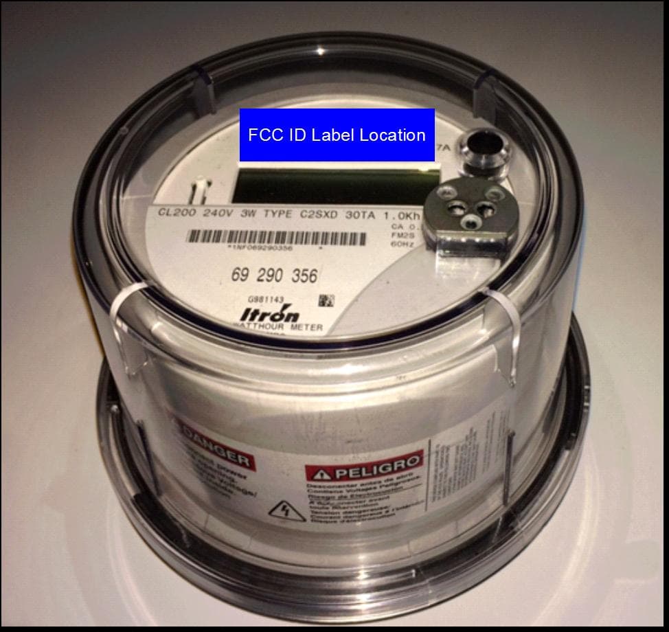
Click to zoom
Application Details
- Equipment Class
- DSS - Part 15 Spread Spectrum Transmitter
- Date of Grant
- Aug 28, 2014
- Application Purpose
- Original Equipment
- Date of Application
- Aug 28, 2014
- Equipment Note
- RDM electricity meter personality module
- Frequency Range
- 910.00000000 - 919.80000000
- Country
- United States
Documents & Files
Document Text
Text extracted from the exhibit documents filed with the FCC. Open a document above to read the original.
Users Manual
August 1, 2014 Page 1 of 4 Rev 1.0 Title RDM User Information Manual Document # D26-0001-004 Document Revision 1.0 Release Date August 1, 2014 Author APPROVALS Author Engineering Product Management (if required) Manufacturing (if required) D26-0001-004 August 1, 2014 Page 2 of 4 Rev 1.0 TABLE OF CONTENTS 1 RDM OVERVIEW ................................................................................................................... 3 2 LABELING REQUIREMENTS ............................................................................................... 3 3 FCC COMPLIANCE STATEMENTS ...................................................................................... 3 4 INSTALLATION AND MODIFICATION ................................................................................. 4 5 ANTENNA .............................................................................................................................. 4 D26-0001-004 August 1, 2014 Page 3 of 4 Rev 1.0 1 RDM OVERVIEW The Nighthawk RDM is an electricity meter personality module that provides wireless capabilities to the host meter. This module includes three transmitters: an ERT radio, RF engine, and cell modem. The ERT radio is a 915 MHz band frequency-hopper which transmits a standard consumption message (SCM) that can be read by a utility’s existing meter reading equipment. The RF engine is a 2.4 GHz transceiver module. The modem transmits metrology data over the cell phone network and receives commands such as remote connect/disconnect. Depending on customer needs the RDM can be delivered with any or all transmitters installed. 2 LABELING REQUIREMENTS All RDM modules with the ERT radio installed shall be labeled with the following text: In addition, the end product shall contain a label that states the following: 3 FCC COMPLIANCE STATEMENTS This equipment has been tested and found to comply with the limits for a Class B digital device, pursuant to part 15 of the FCC Rules. These limits are designed to provide reasonable protection against harmful interference in a residential installation. This equipment generates, uses and can radiate radio frequency energy and, if not installed and used in accordance with the instructions, may cause harmful interference to radio communications. However, there is no guarantee that interference will not occur in a particular installation. If this equipment does cause harmful interference to radio or television reception, which can be determined by turning the equipment off and on, the user is encouraged to try to correct the interference by one or more of the following measures: • Reorient or relocate the receiving antenna. • Increase the separation between the equipment and receiver. • Connect the equipment into an outlet on a circuit different from that to which the receiver is connected. • Consult the dealer or an experienced radio/TV technician for help. This device complies with part 15 of the FCC Rules. Operation is subject to the following two conditions: (1) This device may not cause harmful interference, and (2) this device must accept any interference received, including interference that may cause undesired operation. CONTAINS FCC ID: YJC-RDMERT0 FCC ID: YJC-RDMERT0 D26-0001-004 August 1, 2014 Page 4 of 4 Rev 1.0 4 INSTALLATION AND MODIFICATION This module must be installed to provide a minimum separation distance of 20 cm from all persons, and must not be co-located or operate in conjunction with any other antenna or transmitter. As this module will only be installed in Nighthawk products, Nighthawk retains responsibility for compliance of the final product. WARNING: To ensure FCC compliance and system performance, this assembly shall not be changed or modified without the express written approval of Nighthawk. Any unauthorized modification will void the user’s authority to operate the equipment. 5 ANTENNA The ERT antenna is a folded quarter-wave monopole printed circuit trace, connected through a match network. The antenna has a designed maximum gain of 5.0 dBi.
External Photos
August 1, 2014 Page 1 of 2 Rev 1.0 Title RDM External Photos Document # D26-0001-002 Document Revision 1.0 Release Date August 1, 2014 Author APPROVALS Author Engineering Product Management (if required) Manufacturing (if required) D26-0001-002 August 1, 2014 Page 2 of 2 Rev 1.0 Figure 1. External Photos: Typical Installation. Figure 2. External Photos: Typical Installation. FCC ID Label FCC ID Label Location
ID Label/Location Info
August 1, 2014 Page 1 of 3 Rev 1.0 Title RDM Label Information Document # D26-0001-011 Document Revision 1.0 Release Date August 1, 2014 Author APPROVALS Author Engineering Product Management (if required) Manufacturing (if required) D26-0001-011 August 1, 2014 Page 2 of 3 Rev 1.0 The RDM will contain a permanent sticker with the contents shown in Figure 1. The sticker will be affixed to the board as indicated by “FCC ID Label” in Figure 2. Figure 1. RDM Sticker. Figure 2. RDM Sticker Affixed to Board. FCC ID: YJC-RDMERT0 FCC ID Label D26-0001-011 August 1, 2014 Page 3 of 3 Rev 1.0 The host meter will contain a label such as the one shown in Figure 3. The label will be placed on the outside of the host meter at the location shown in Figure 4. Figure 3. Host Meter Label. Figure 4. Host Meter Label Location. RDM Series XXXXXXXXXXXXXXXX CONTAINS FCC ID: YJC-RDMERT0 ERT: YYYYYYYY N
Internal Photos
August 1, 2014 Page 1 of 3 Rev 1.0 Title RDM Internal Photos Document # D26-0001-003 Document Revision 1.0 Release Date August 1, 2014 Author APPROVALS Author Engineering Product Management (if required) Manufacturing (if required) D26-0001-003 August 1, 2014 Page 2 of 3 Rev 1.0 Figure 1. Internal Photos – Top Side. FCC ID Label D26-0001-003 August 1, 2014 Page 3 of 3 Rev 1.0 Figure 2. Internal Photos – Bottom Side. FCC ID Label
RF Exposure Info
FCC ID: YJC-RDMERT0 Model: RDM There are 3 radios on board. They only transmit one at a time. So there is no simultaneous transmission. Novatel HS 3001 cell modem (FCC ID MIVCNN0301) and Synapse SM200 RF engine (FCC ID U9O-SM200) have their RF exposure compliance addressed in their corresponding filings with the FCC. This document addresses RF exposure compliance for the ERT radio (910.0-919.8MHz) in this application. Host product Itron C2SXD Form 2S Electric Meter is installed more than 20cm away from nearby people and ERT radio antenna is a folded quarter-wave monopole printed circuit trace antenna internal to the host. Maximum peak output power at the antenna terminal and declared antenna gain are listed on Pg 16 of the test report and are used in the following equation. Power density at 20cm is based on Where: S = power density P = power input to the antenna G = power gain of the antenna in the direction of interest relative to an isotropic radiator R = distance to the center of radiation of the antenna Maximum peak output power at the antenna terminal:8.93(dBm) Maximum peak output power at the antenna terminal:7.816278046(mW) Antenna gain(typical): 5(dBi) Maximum antenna gain:3.16227766(numeric) Prediction distance:20(cm) Prediction frequency: 915(MHz) MPE limit for uncontrolled exposure at prediction frequency:0.61(mW/cm^2) Power density at prediction frequency:0.004917(mW/cm^2) Therefore device complies with FCC RF radiation exposure limits for general population in mobile exposure category (distance > 20cm) 2 4R PG S π =
Test Report
NTS Test Report No. PR030492 1 of 20 Intentional Radiator Test Report Application for Grant of Equipment Authorization FCC Part 15 Subpart C (15.247) FCC ID: YJC-RDMERT0 Product Name: Nighthawk RDM960 Personality Module Model: RDM APPLICANT: AMI Investments LLC d.b.a Nighthawk 701 Canyon Drive Suite 105 Coppell TX, 75019 TEST SITE(S): National Technical Systems - Plano 1701 E Plano Pkwy #150 Plano, TX 75074 REPORT DATE: Aug 6, 2014 FINAL TEST DATES: July 16-17, 2014 TOTAL NUMBER OF PAGES: 20 Prepared By: Approved By: ______________________________ _______________________ Yunus E. Faziloglu Kimberly Zavala Wireless Manager Quality Assurance Manager Reviewed By: ______________________________ John Ngo General Manager This report and the information contained herein represent the results of testing test articles identified and selected by the client performed to specifications and/or procedures selected by the client. National Technical Systems (NTS) makes no representations, expressed or implied, that such testing is adequate (or inadequate) to demonstrate efficiency, performance, reliability, or any other characteristic of the articles being tested, or similar products. This report should not be relied upon as an endorsement or certification by NTS of the equipment tested, nor does it represent any statement whatsoever as to its merchantability or fitness of the test article, or similar products, for a particular purpose. This report shall not be reproduced except in full. NTS Plano -- EMC Department NTS Test Report No. PR030492 Report Date: Aug 6, 2014 2 of 20 REVISION HISTORY Rev# Date Comments Modified By 0 Aug 6, 2014 First Release Yunus Faziloglu NTS Plano -- EMC Department NTS Test Report No. PR030492 Report Date: Aug 6, 2014 3 of 20 TABLE OF CONTENTS REVISION HISTORY ................................................................................................................................................ 2 TABLE OF CONTENTS ............................................................................................................................................ 3 SCOPE .......................................................................................................................................................................... 4 OBJECTIVE ................................................................................................................................................................ 4 STATEMENT OF COMPLIANCE ........................................................................................................................... 4 DEVIATIONS FROM THE STANDARDS .............................................................................................................. 5 MODIFICATIONS ...................................................................................................................................................... 5 MEASUREMENT UNCERTAINTIES ..................................................................................................................... 5 TEST RESULTS SUMMARY .................................................................................................................................... 6 EQUIPMENT UNDER TEST (EUT) DETAILS ...................................................................................................... 7 EUT OPERATION ...................................................................................................................................................... 8 TEST SITE ................................................................................................................................................................... 8 TEST EQUIPMENT.................................................................................................................................................... 8 TEST RESULTS SECTION ....................................................................................................................................... 9 AC LINE CONDUCTED EMISSIONS ...................................................................................................................... 10 20DB BANDWIDTH ................................................................................................................................................ 12 CHANNEL SEPARATION ........................................................................................................................................ 13 NUMBER OF HOPPING CHANNELS ...................................................................................................................... 14 DWELL TIME .......................................................................................................................................................... 15 PEAK CONDUCTED OUTPUT POWER ................................................................................................................... 16 BANDEDGE COMPLIANCE .................................................................................................................................... 17 RADIATED SPURIOUS EMISSIONS ....................................................................................................................... 18 END OF REPORT ..................................................................................................................................................... 20 NTS Plano -- EMC Department NTS Test Report No. PR030492 Report Date: Aug 6, 2014 4 of 20 SCOPE Tests have been performed on the AMI Investments LLC product Nighthawk RDM960 Personality Module Model RDM to demonstrate compliance with the following rules: FCC Part 15 Subpart C (15.247) Conducted and radiated emissions data has been collected, reduced, and analyzed within this report in accordance with measurement guidelines set forth in the following reference standards and as outlined in National Technical Systems – Plano test procedures: ANSI C63.4-…
Text truncated - open the document above for the full version.
Test Setup Photos
Radiated Emissions Front Radiated Emissions Rear Radiated Emissions 30MHz-1GHz Radiated Emissions 1GHz-10GHz AC Line Conducted Emissions Front AC Line Conducted Emissions Rear
Contact Information
Applicant
Weimin Peng(RF Engineer)
[email protected]972-207-0917
Test Firm
National Technical Systems (NTS)Kimberly Zavala
Technical Specifications
| # | Rule Parts | Frequency Range | Power Output |
|---|---|---|---|
| 1 | 15C | 910 MHz - 919.8 MHz | 8.00 mW |
Other Applications from AMI Investments, LLC d.b.a. Nighthawk
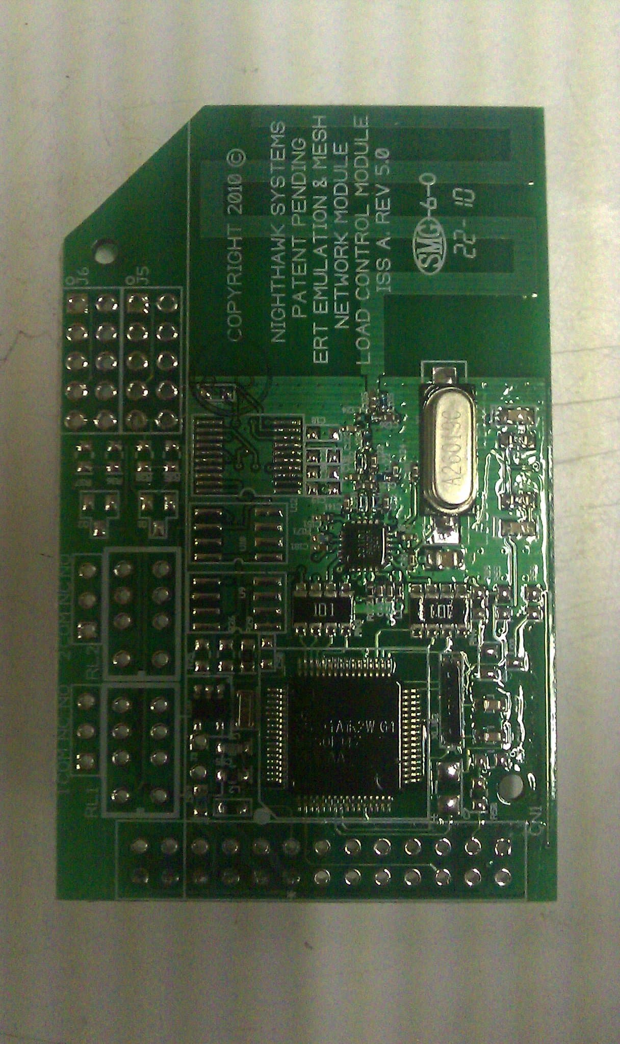
YJC-MESHERT006
Jul 14, 2010Single Board Radio Module
Equipment Class
DSS - Part 15 Spread Spectrum Transmitter