YJKSE6XTransceiver Unit 2.4 GHz
DR. JOHANNES HEIDENHAIN GmbH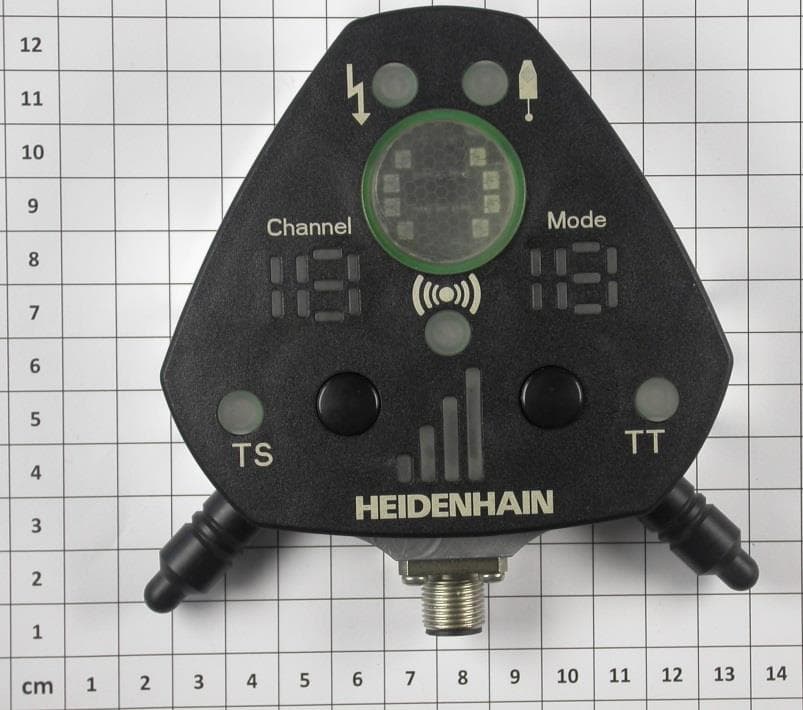
Click to zoom
Application Details
- Equipment Class
- DXX - Part 15 Low Power Communication Device Transmitter
- Date of Grant
- Aug 04, 2013
- Application Purpose
- Original Equipment
- Date of Application
- Aug 04, 2013
- Equipment Note
- Transceiver Unit 2.4 GHz
- Frequency Range
- 2405.00000000 - 2480.00000000
- Company
- DR. JOHANNES HEIDENHAIN GmbH
- Country
- Germany
Documents & Files
Document Text
Text extracted from the exhibit documents filed with the FCC. Open a document above to read the original.
Users Manual
SE 660 7/2013 Montageanleitung Mounting Instructions Instructions de montage Istruzioni di montaggio Instrucciones de montaje 取付説明書 安装说明 安裝指導手冊 설치 지침 preliminary Índice Página 4 Notas de aviso 8 Approval for radio transmission 14 Dimensiones 16 Accesorio para el montaje 18 Tensión de alimentación 20 Transmisión de la señal 22 Estado del palpador 26 Distribución del conector 28 Características técnicas Indice Pagina 4 Avvertenze 8 Approval for radio transmission 14 Dimensioni 16 Accessori di montaggio 18 Tensione di alimentazione 20 Trasmissione del segnale 22 Stato del sistema di tastatura 26 Piedinatura 28 Dati tecnici Sommaire Page 4 Avertissement 8 Approval for radio transmission 14 Dimensions 16 Accessoire de montage 18 Tension d’alimentation 20 Transmission du signal 22 Etat du palpeur 26 Raccordements 28 Caractéristiques techniques Contents Page 4 Warnings 8 Approval for radio transmission 14 Dimensions 16 Mounting accessories 18 Power supply 20 Signal transmission 22 Status of the touch probe 26 Pin Layout 28 Specifications 2 InhaltSeite 4 Warnhinweise 8 Funkerlaubnis 14 Abmessungen 16 Montagezubehör 18 Spannungsversorgung 20 Signalübertragung 22 Zustand des Tastsystem 26 Anschlussbelegung 28 Technische Kennwerte 목차 페이지 6 경고 12 Approval for radio transmission 9 규격 11 설치용 부속품 13 전원 공급 15 신호 전송 17 터치 프로브의 상태 21 핀 레이아웃 23 사양 目錄 頁碼 6 警告 12 Approval for radio transmission 9 尺寸 11 安裝零件 13 供應電壓 15 信號傳輸 17 接觸式探針狀態 21 接腳配置 23 規格 目录 页 6 提示 12 Approval for radio transmission 9 尺寸 11 安装附件 13 电源 15 信号传输 17 测头状态 21 针脚编号 23 技术参数 目次 ページ 6 注意事項 12 Approval for radio transmission 9 寸法 11 取付け用別売アクセサリ 13 電源 15 信号伝送方式 17 タッチプローブの状態 21 ピン配列 23 仕様 3 ContentsPage 6 Warnings 12 Approval for radio transmission 9 Dimensions 11 Mounting accessories 13 Power supply 15 Signal transmission 17 Status of the touch probe 21 Pin Layout 23 Specifications Notas de aviso Atención: El montaje y la puesta en marcha deben ser realizados por un especialista cualificado, observando las prescripciones locales de seguridad. Conectar o desconectar el conector sólo en ausencia de tensión. Avvertenze Attenzione: Il montaggio e la messa in funzione devono essere eseguite da personale qualifucato nel rispetto delle norme di sicurezza locali. I cavi posso essere collegati o scollegati solo in assenza di tensione. Avertissement Attention: le montage et la mise en service doivent être assurés par un personnel qualifié dans le respect des consignes de sécurité locales. Le connecteur ne doit être connecté ou déconnecté qu’hors potentiel. Warnings Note: Mounting and commissioning is to be conducted by a qualified specialist under compliance with local safety regulations. Do not engage or disengage any connections while under power. 4 Warnhinweise Achtung: Die Montage und Inbetriebnahme ist von einer qualifizierten Fachkraft unter Beachtung der örtlichen Sicherheitsvorschriften vorzunehmen. Die Steckverbindung darf nur spannungsfrei verbunden oder gelöst werden. No dejar caer el palpador. Positionsmessgeräte nur aus PELV-Systemen (EN 50178) speisen. Hochfrequent niederohmige Erdung (EN 60204-1 Kap. EMV) vorsehen. Non far cadere il tastatore. Positionsmessgeräte nur aus PELV-Systemen (EN 50178) speisen. Hochfrequent niederohmige Erdung (EN 60204-1 Kap. EMV) vorsehen. Ne pas laisser tomber le palpeur. Positionsmessgeräte nur aus PELV-Systemen (EN 50178) speisen. Hochfrequent niederohmige Erdung (EN 60204-1 Kap. EMV) vorsehen. Do not drop the touch probe. Positionsmessgeräte nur aus PELV-Systemen (EN 50178) speisen. Hochfrequent niederohmige Erdung (EN 60204-1 Kap. EMV) vorsehen. 5 Tastsystem nicht fallen lassen. Provide power to position encoders only from PELV systems (EN 50178). Provide high-frequency grounding with low impedance (EMC chapter in EN 60204-1). 경고 주의: 설치 및 조정은 한국의 안전도 규정에 의하여 작업을 수행할 수 있는 공인된 기술자에 의해 수행되어야 합니다. 전기가 공급된 상황에서는 절대로 연결 또는 분리를 하지 마세요. 警告 注意:安裝與調整要經由已認證的專業人員指導以符合當地安全規範要求。 當電源開啟時,請勿連接或拔除連接電纜。 提示 注意: 安装和调试时必须符合当地安全要求并由具有资质的专业人员操作。 带电时,严禁连接或断开任何接线。 注意事項 注意:取付け及び試運転は設置国の安全規格のもとで有資格の専門家により実施するようにし てください。 製品の取付けあるいは取外しは、給電されていないときに行ってください。 6 Warnings Note: Mounting and commissioning is to be conducted by a qualified specialist under compliance with local safety regulations. Do not engage or disengage any connections while under power. 터치 프루브를 떨어뜨리면 않됩니다. Provide power to position encoders only from PELV systems (EN 50178). Provide high-frequency grounding with low impedance (EMC chapter in EN 60204-1). 探針請勿掉落. Provide power to position encoders only from PELV systems (EN 50178). Provide high-frequency grounding with low impedance (EMC chapter in EN 60204-1). 请不要使测头跌落. Provide power to position encoders only from PELV systems (EN 50178). Provide high-frequency grounding with low impedance (EMC chapter in EN 60204-1). タッチプローブを落とさないでください. Provide power to position encoders only from PELV systems (EN 50178). Provide high-frequency grounding with low impedance (EMC chapter in EN 60204-1). 7 Do not drop the touch probe. Provide power to position encoders only from PELV systems (EN 50178). Provide high-frequency grounding with low impedance (EMC chapter in EN 60204-1). Funkerlaubnis Für den Betrieb im Funkmodus Funkerlaubnis Für den Betrieb im Funkmodus Funkerlaubnis Für den Betrieb im Funkmodus Funkerlaubnis Für den Betrieb im Funkmodus 8 USA FCC User information (USA only) acc. Section 15.19 This device complies with Part 15 of the FCC Rules. Operation is subject to the following two conditions: (1) this device may not cause harmful interference, and (2) this device must accept any interference received, including interference that may cause undesired operation. acc. Section 15.21 Changes or modifications not expressly approved by the party responsible for compliance could void the user’s authority to operate the equipment. FCC ID YJKSE6X Approval for radio transmission For operation in radio mode 9 acc. Section 15.105 NOTE: This equipment has been tested and found to comply with the limits for a Class B digital device, pu…
Text truncated - open the document above for the full version.
Cover Letter(s)
Request for Confidentiality Date: 25.07.2013 Subject: Confidentiality Request for: FCC ID: YJKSE6X IC: 11148A-SE6X Pursuant to FCC 47 CRF 0.457(d) and 0.459 and IC RSP-100, Section 10, the applicant requests that a part of the subject FCC application be held confidential. Type of Confidentiality Requested Exhibit Short Term Permanent Block Diagrams Short Term External Photos Short Term Permanent* 1 Internal Photos Short Term Permanent Operation Description/Theory of Operation Short Term Permanent Parts List & Placement/BOM Short Term Permanent Tune-Up Procedure Short Term Permanent Schematics Short Term Test Setup Photos Short Term Permanent* User’s Manual *Note: ______(Insert Explanation as Necessary)______ Dr. Johannes Heidenhain GmbH has spent substantial effort in developing this product and it is one of the first of its kind in industry. Having the subject information easily available to "competition" would negate the advantage they have achieved by developing this product. Not protecting the details of the design will result in financial hardship. Permanent Confidentiality: The applicant requests the exhibits listed above as permanently confidential be permanently withheld from public review due to materials that contain trade secrets and proprietary information not customarily released to the public. Short-Term Confidentiality: The applicant requests the exhibits selected above as short term confidential be withheld from public view for a period of (180) days from the date of the Grant of Equipment Authorization and prior to marketing. This is to avoid premature release of sensitive information prior to marketing or release of the product to the public. Applicant is also aware that they are responsible to notify ACB in the event information regarding the product or the product is made available to the public. ACB will then release the documents listed above for public disclosure pursuant to FCC Public Notice DA 04-1705. NOTE for Industry Canada Applications: The applicant understands that until such time that IC distinguishes between Short Term and Permanent Confidentiality, either type of marked exhibit above will simply be marked Confidential when submitted to IC. Sincerely, By: Manager Certification Thomas Ring 1 - The asterisked items (*) require further justification before permanent confidentiality will be allowed. These also currently require review by the FCC under their Permit-But-Ask policy before the grant is issued and can delay completion of an application. Further justification should be added to the note above. One such example for a potted device would be: “The EUT is FULLY potted using a non-removable epoxy based material. Removal of potting material causes irreparable damage to internal circuitry. See photographs exhibits that outline the device before and after potting.”
External Photos
FCC ID: YJKSE6X IC ID: 11148A-SE6X mikes-testingpartners gmbh File No. T36611-00-01HS, page 34 of 37 Ohmstrasse 2-4 94342 STRASSKIRCHEN GERMANY Tel.:+49(0)9424-94810 Fax:+49(0)9424-9481240 Rev. No. 1.2, 2010-09-09 A t t a c h m e n t A Transceiver unit SE 660 External view:
Internal Photos
FCC ID: YJKSE6X IC ID: 11148A-SE6X mikes-testingpartners gmbh File No. T36611-00-01HS, page 35 of 37 Ohmstrasse 2-4 94342 STRASSKIRCHEN GERMANY Tel.:+49(0)9424-94810 Fax:+49(0)9424-9481240 Rev. No. 1.2, 2010-09-09 Internal view: FCC ID: YJKSE6X IC ID: 11148A-SE6X mikes-testingpartners gmbh File No. T36611-00-01HS, page 36 of 37 Ohmstrasse 2-4 94342 STRASSKIRCHEN GERMANY Tel.:+49(0)9424-94810 Fax:+49(0)9424-9481240 Rev. No. 1.2, 2010-09-09 FCC ID: YJKSE6X IC ID: 11148A-SE6X mikes-testingpartners gmbh File No. T36611-00-01HS, page 37 of 37 Ohmstrasse 2-4 94342 STRASSKIRCHEN GERMANY Tel.:+49(0)9424-94810 Fax:+49(0)9424-9481240 Rev. No. 1.2, 2010-09-09
Test Report
FCC ID: YJKSE6X IC ID: 11148A-SE6X mikes-testingpartners gmbh File No. T36611-00-01HS, page 1 of 39 Ohmstrasse 2-4 94342 STRASSKIRCHEN GERMANY Tel.:+49(0)9424-94810 Fax:+49(0)9424-9481240 Rev. No. 1.2, 2010-09-09 EMI − T E S T R E P O R T - FCC Part 15.249, RSS210 - Test Report No. : T36611-00-01HS 31. July 2013 ______________________________________________________________________________________________ Date of issue Type / Model Name : SE660 Product Description : Transceiver unit 2.4 GHz Applicant : Dr. Johannes Heidenhain GmbH Address : Dr. Johannes-Heidenhain-Str. 5 83301 TRAUNREUT Manufacturer : Dr. Johannes Heidenhain GmbH Address : Dr. Johannes-Heidenhain-Str. 5 83301 TRAUNREUT Licence holder : Dr. Johannes Heidenhain GmbH Address : Dr. Johannes-Heidenhain-Str. 5 83301 TRAUNREUT Test Result according to the standards listed in clause 1 test standards: POSITIVE The test report merely corresponds to the test sample. It is not permitted to copy extracts of these test results without the written permission of the test laboratory. FCC ID: YJKSE6X IC ID: 11148A-SE6X mikes-testingpartners gmbh File No. T36611-00-01HS, page 2 of 39 Ohmstrasse 2-4 94342 STRASSKIRCHEN GERMANY Tel.:+49(0)9424-94810 Fax:+49(0)9424-9481240 Rev. No. 1.2, 2010-09-09 Contents 1 T E S T S T A N D A R D S 3 2 S U M M A R Y 4 2.1 GENERAL REMARKS: 4 2.1 Test result summery 5 2.2 FINAL ASSESSMENT: 5 3 E Q U I P M E N T U N D E R T E S T 6 3.1 Photo documentation of the EUT – Please see attachment A 6 3.2 Power supply system utilised 6 3.3 Short description of the equipment under test (EUT) 6 4 T E S T E N V I R O N M E N T 7 4.1 Address of the test laboratory 7 4.2 Environmental conditions 7 4.3 Statement of the measurement uncertainty 7 4.4 Measurement protocol for FCC and IC 8 4.5 Determination of worst case measurement conditions 8 5 T E S T C O N D I T I O N S A N D R E S U L T S 9 5.1 AC power line conducted emissions 9 5.2 Field strength of fundamental emission 13 5.3 Out-of-band emission, radiated 15 5.4 EBW and OBW 26 5.5 Correction for pulse operation (duty cycle) 31 5.6 Antenna application 33 6 U S E D T E S T E Q U I P M E N T A N D A C C E S S O R I E S 34 A t t a c h m e n t A 35 FCC ID: YJKSE6X IC ID: 11148A-SE6X mikes-testingpartners gmbh File No. T36611-00-01HS, page 3 of 39 Ohmstrasse 2-4 94342 STRASSKIRCHEN GERMANY Tel.:+49(0)9424-94810 Fax:+49(0)9424-9481240 Rev. No. 1.2, 2010-09-09 1 T E S T S T A N D A R D S The tests were performed according to following standards: FCC Rules and Regulations Part 15, Subpart A - General (September, 2012) Part 15, Subpart A, Section 15.31 Measurement standards Part 15, Subpart A, Section 15.33 Frequency range of radiated measurements Part 15, Subpart A, Section 15.35 Measurement detector functions and bandwidths FCC Rules and Regulations Part 15, Subpart C - Intentional Radiators (September, 2012) Part 15, Subpart C, Section 15.203 Antenna requirement Part 15, Subpart C, Section 15.204 External radio frequency power amplifiers and antenna modifications Part 15, Subpart C, Section 15.205 Restricted bands of operation Part 15, Subpart C, Section 15.207 Conducted limits Part 15, Subpart C, Section 15.209 Radiated emission limits, general requirements Part 15, Subpart C, Section 15.249 Operation within the bands 902 - 928 MHz, 2400 - 2483.5 MHz, 5725 - 5875 MHz, and 24.0 - 24.25 GHz ANSI C63.4: 2003 Methods of Measurement of Radio-Noise Emissions from Low- Voltage Electrical and Electronic Equipment in the Range of 9 kHz to 40 GHz. ANSI C95.1:2005 IEEE Standard for Safety Levels with respect to Human Exposure to Radio Frequency Electromagnetic Fields, 3 kHz to 300 GHz CISPR 16-4-2: 2003 Uncertainty in EMC measurement CISPR 22: 2005 Information technology equipment EN 55022: 2006 FCC ID: YJKSE6X IC ID: 11148A-SE6X mikes-testingpartners gmbh File No. T36611-00-01HS, page 4 of 39 Ohmstrasse 2-4 94342 STRASSKIRCHEN GERMANY Tel.:+49(0)9424-94810 Fax:+49(0)9424-9481240 Rev. No. 1.2, 2010-09-09 2 S U M M A R Y 2.1 GENERAL REMARKS: The EUT is a 2.4 GHz – transceiver unit for low power data transmission in 16 channels of the operating band of 2.4 GHz to 2.4835 GHz. The transceiver unit stays in contact to the installed touch probe and acknowledge every successful received data frame. The transceiver unit use for diversity four parallel transceiver trees with identically RF parts, 2 PCB antennas and 2 dedicated antennas. Special test software is used for setting the test modes. Variants of the EUT There are no variants. Antennas The following integrated antennas are used with the EUT: - PCB meander antenna for transceiver unit and touch probe . - Dedicated antenna for transceiver unit (flagpole antenna). The antennas cannot be unattached by the user. Operation frequency and channel plan The operating frequency is 2400 MHz to 2483.5 MHz. Transmit operating modes The EUT use O-QPSK and provide following data rate: 250 kbps (kbps = kilobits per second) Channel Nof 02405 12410 22415 32420 42425 52430 62435 72440 82445 92450 102455 112460 122465 132470 142475 152480 FCC ID: YJKSE6X IC ID: 11148A-SE6X mikes-testingpartners gmbh File No. T36611-00-01HS, page 5 of 39 Ohmstrasse 2-4 94342 STRASSKIRCHEN GERMANY Tel.:+49(0)9424-94810 Fax:+49(0)9424-9481240 Rev. No. 1.2, 2010-09-09 2.1 Test result summery Operating in the 2400 MHz – 2483.5 MHz band: FCC Rule Part RSS Rule Part Description Result 15.35(c) RSS-Gen, 4.5 Pulsed operation passed 15.203 RSS Gen, 7.1.2 Antenna requirement passed 15.204 RSS Gen, 7.1.1 External radio frequency power amplifiers passed 15.205(a) RSS-Gen, 7.2.2 Emissions in restricted bands passed 15.207(a) RSS Gen, 7.2.4 AC power line conducted emissions passed 15.215(c) EBW passed RSS-Gen, 4.6.1 OBW passed 15.249(a) RSS-210, A2.9(a) Field strength of fundamental passed 15.249(d) RSS Gen, 7.2.5 Out-of-band emission, radiated passed RSS-Gen, 7.2.6 Transmitter frequency stability not applicable The mentioned RSS Rule Parts in the above tab…
Text truncated - open the document above for the full version.
Test Setup Photos
FCC ID: YJKSE6X IC ID: 11148A-SE6X mikes-testingpartners gmbh File No. T36611-00-01HS, page 9 of 37 Ohmstrasse 2-4 94342 STRASSKIRCHEN GERMANY Tel.:+49(0)9424-94810 Fax:+49(0)9424-9481240 Rev. No. 1.2, 2010-09-09 5 T E S T C O N D I T I O N S A N D R E S U L T S 5.1 AC power line conducted emissions For test instruments and accessories used see section 6 Part A 4. 5.1.1 Description of the test location Test location: AREA4 5.1.2 Photo documentation of the test set-up 5.1.3 Applicable standard According to FCC Part 15, Section 15.207(a): Except as shown in paragraphs (b) and (c) of this Section, for an intentional radiator that is designed to be connected to the public utility (AC) power line, the radio frequency voltage that is conducted back onto the AC power line on any frequency or frequencies within the band 150 kHz to 30 MHz shall not exceed the given limits. 5.1.4 Description of Measurement The measurements are performed following the procedures set out in ANSI C63.4 described under item 4.4.3. If the minimum limit margin appears to be less than 20 dB with a peak mode measurement, the emissions are re- measured using a tuned receiver with quasi-peak and average detection and recorded on the data sheets. 5.1.5 Test result Frequency range: 0.15 MHz - 30 MHz Min. limit margin -23.1 dB at 0.68 MHz FCC ID: YJKSE6X IC ID: 11148A-SE6X mikes-testingpartners gmbh File No. T36611-00-01HS, page 13 of 37 Ohmstrasse 2-4 94342 STRASSKIRCHEN GERMANY Tel.:+49(0)9424-94810 Fax:+49(0)9424-9481240 Rev. No. 1.2, 2010-09-09 5.2 Field strength of fundamental emission For test instruments and accessories used see section 6 Part CPR 3. 5.2.1 Description of the test location Test location: Anechoic chamber 2 Test distance: 3 m 5.2.2 Photo documentation of the test set-up 5.2.1 Applicable standard According to FCC Part 15C, Section 15.249(a): The field strength of emission from intentional radiators operated within these frequency bands shall comply with the limit in the table. 5.2.2 Description of Measurement The radiated emission of the fundamental wave from the EUT is measured using a spectrum analyser and appropriate linear polarized antennas. The setup of the EUT and the measurement procedure is in accordance to ANSI C63.4, Item 8.3. The EUT is measured in TX continuous mode unmodulated under normal conditions. Analyser settings: Peak measurement: RBW: 1 MHz VBW: 1 MHz Detector: Max peak AV measurement: RBW: 1 MHz VBW: 10 Hz Detector: Max peak FCC ID: YJKSE6X IC ID: 11148A-SE6X mikes-testingpartners gmbh File No. T36611-00-01HS, page 15 of 37 Ohmstrasse 2-4 94342 STRASSKIRCHEN GERMANY Tel.:+49(0)9424-94810 Fax:+49(0)9424-9481240 Rev. No. 1.2, 2010-09-09 5.3 Out-of-band emission, radiated For test instruments and accessories used see section 6 Part SER1, SER 2, SER 3. 5.3.1 Description of the test location Test location: OATS 1 Test location: Anechoic chamber 2 Test distance: 3 m 5.3.2 Photo documentation of the test setup Test setup 9 kHz – 30 MHz: FCC ID: YJKSE6X IC ID: 11148A-SE6X mikes-testingpartners gmbh File No. T36611-00-01HS, page 16 of 37 Ohmstrasse 2-4 94342 STRASSKIRCHEN GERMANY Tel.:+49(0)9424-94810 Fax:+49(0)9424-9481240 Rev. No. 1.2, 2010-09-09 Test setup 30 MHz – 1000 MHz: Test setup 1 GHz – 18 GHz: FCC ID: YJKSE6X IC ID: 11148A-SE6X mikes-testingpartners gmbh File No. T36611-00-01HS, page 17 of 37 Ohmstrasse 2-4 94342 STRASSKIRCHEN GERMANY Tel.:+49(0)9424-94810 Fax:+49(0)9424-9481240 Rev. No. 1.2, 2010-09-09 Test setup 18 GHz – 25 GHz: 5.3.3 Applicable standard According to FCC Part 15C, Section 15.249 (d): Emission radiated outside of the specified frequency bands, except harmonics, shall be attenuated by at least 50 dB below the level of the fundamental or to the general radiated limit in FCC Part 15C, Section 15.209, whichever is the lesser attenuation. 5.3.4 Description of Measurement The radiated emissions from the EUT are measured in the frequency range of 9 kHz to 1000 MHz using a tuned receiver and appropriate broadband linearly polarized antennas. The setup of the EUT and the measurement procedure is in accordance to ANSI C63.4, Item 8.3. In the frequency range above 1 GHz a spectrum analyser is used with appropriate linear polarized antennas. If the emission level in peak mode complies with the average limit testing is stopped and peak values will be reported, otherwise, the emission is measured in average mode again and reported. The EUT is measured in TX continuous mode unmodulated under normal conditions. Instrument settings: 9 kHz – 150 kHz RBW: 200 Hz 150 kHz - 30 MHz RBW: 9 kHz 30 MHz – 1000 MHz: RBW: 120 kHz 1000 MHz – 25 GHz RBW: 1 MHz FCC ID: YJKSE6X IC ID: 11148A-SE6X mikes-testingpartners gmbh File No. T36611-00-01HS, page 26 of 37 Ohmstrasse 2-4 94342 STRASSKIRCHEN GERMANY Tel.:+49(0)9424-94810 Fax:+49(0)9424-9481240 Rev. No. 1.2, 2010-09-09 5.4 EBW and OBW For test instruments and accessories used see section 6 Part MB. 5.4.1 Description of the test location Test location: AREA4 5.4.2 Photo documentation of the test set-up 5.4.3 Applicable standard According to FCC Part 15, Section 15.215(c): Intentional radiators operating under the alternative provisions to the general emission limits, as contained in Section 15.217 through Section 15.257, must be designed to ensure that the 20 dB bandwidth of the emission is contained within the frequency band designated in the rule section under which the equipment is operated. 5.4.4 Description of Measurement The bandwidth is measured at an amplitude level reduced from the reference level by a specified ratio of -20 dB (99%). The x-dB-down (OBW) function of the analyser is used. The measurement is performed with normal modulation in TX continuous mode. Spectrum analyser settings: RBW: 30 kHz, VBW: 100 kHz, Span: 6 MHz, Trace mode: max. hold, Detector: max. peak; FCC ID: YJKSE6X IC ID: 11148A-SE6X mikes-testingpartners gmbh File No. T36611-00-01HS, page 30 of 37 Ohmstrasse 2-4 94342 STRASS…
Text truncated - open the document above for the full version.
Contact Information
Applicant
Eduard Schroll(Head of R&D, Hardware NC I)
Technical Contact
Test Firm
CSA Group Bayern GmbHThomas Weise
Technical Specifications
| # | Rule Parts | Frequency Range | Power Output |
|---|---|---|---|
| 1 | 15C | 2.40 GHz - 2.48 GHz | - |
Other Applications from DR. JOHANNES HEIDENHAIN GmbH
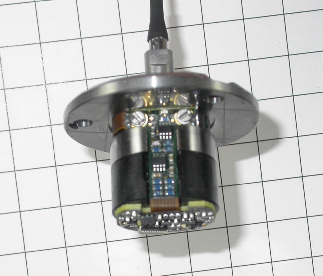
YJKTSX6TTX6
Aug 07, 2013Touch Probe 2.4 GHz
Equipment Class
DXX - Part 15 Low Power Communication Device Transmitter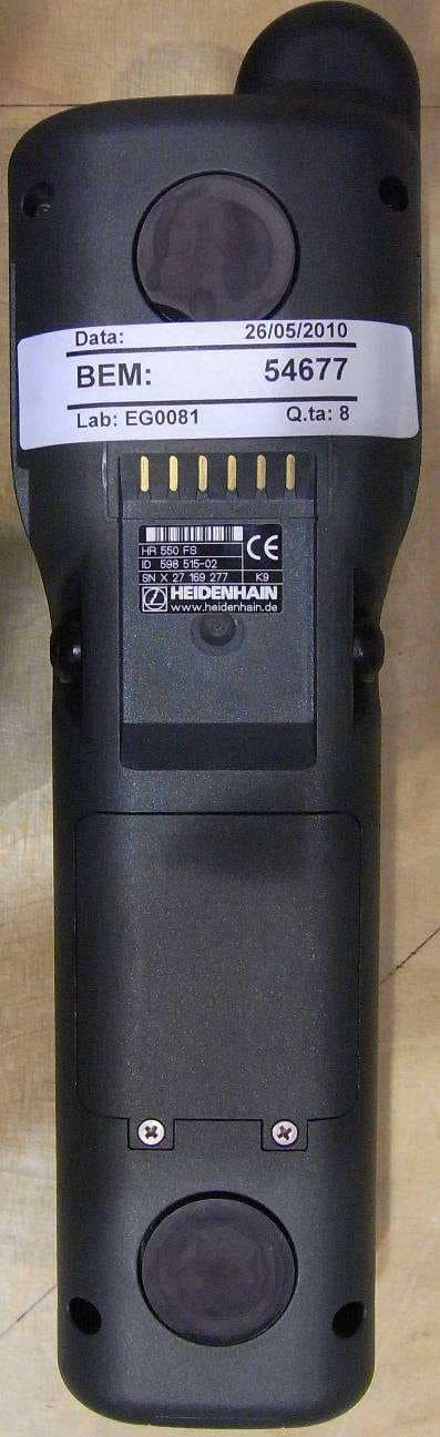
YJKHR550FS
Aug 04, 2011Wireless Handwheel System - Handwheel
Equipment Class
DTS - Digital Transmission System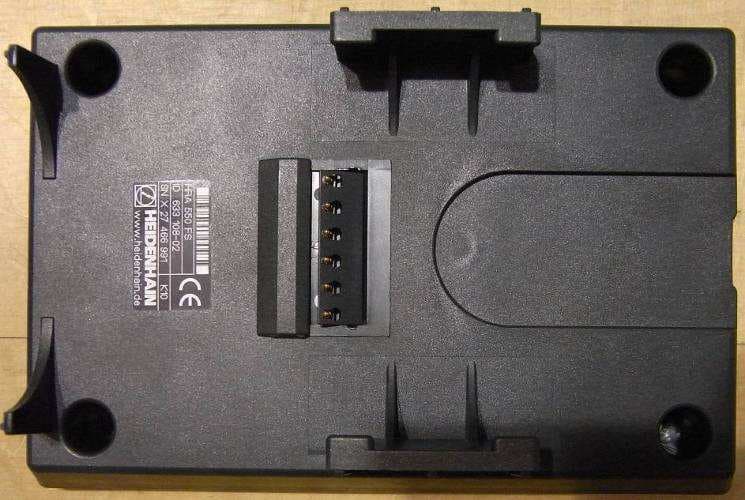
YJKHRA550FS
Aug 04, 2011Wireless Handwheel System - Access Point
Equipment Class
DTS - Digital Transmission System