YK4-JW9-8A2F0-00TRANSMITTING UNIT
YAMAHA MOTOR POWERED PRODUCTS CO., LTD.
Click to zoom
Application Details
- Equipment Class
- DXT - Part 15 Low Power Transceiver, Rx Verified
- Date of Grant
- Sep 15, 2010
- Application Purpose
- Original Equipment
- Date of Application
- Sep 15, 2010
- Equipment Note
- TRANSMITTING UNIT
- Frequency Range
- 923.59320000 - 923.59320000
- Country
- Japan
Documents & Files
Document Text
Text extracted from the exhibit documents filed with the FCC. Open a document above to read the original.
Users Manual
䇭1. Introduction of the product These devices make it possible to efficiently manage and maintain numerous YDRE's in a single golf course. 䇭2. Parts and descriptions 䇭(1) Parent device 䇭(2) Relay device LAN cable IN 䌁䌃 adapter Radio antenna Body 䌌䌅䌄 䌁䌃 adapter 䌄䌃 Jack bracket for wall surface installation NSYPFPLM Transmitter (The general term Parent device in the text means a BASE ASSY.) (The general term Relay device in the text means a TRANSMITTING UNIT.) 䇭3. Installation 䇭(1) Parent device Install this device indoors, near the window, and at 150cm or higher from the floor. 䇭䊶㪠㫅㫊㫋㪸㫃㫃㩷㫋㪿㫀㫊㩷㫇㪸㫉㪼㫅㫋㩷㪻㪼㫍㫀㪺㪼㩷㪠㫅㪻㫆㫆㫉㫊㪃㩷㫅㪼㪼㫉㩷㪸㩷㫎㫀㫅㪻㫆㫎㪃㩷㪸㫋㩷㪸㩷㪿㪼㫀㪾㪿㫋㩷㫆㪽 㩷㩷㩷㪸㫋㩷㫃㪼㪸㫊㫋㩷㪈㪌㪇㪺㫄㩷㪽㫉㫆㫄㩷㫋㪿㪼㩷㪽㫃㫆㫆㫉㪅 䇭䊶Install this device as far away from the metal object as possible, 䇭䇭㫊uch as metal blinds, glass with steel wires, etc. 䇭䊶Install this device as far away from 100BASE-T or higher devices as possible. 䇭䊶Install a lightening guard on the AC outlet. 㩷㩷䊶㪞㪝㪚㪠㩷㫆㫌㫋㫃㪼㫋㩷㫆㫅㫃㫐㪅 䇭(2) Relay device Install the relay device on the wall near the entrance to the cart barn, and at least 150cm above the ground. 䇭䊶Select a location not subject to direct wind or rain which can support the weight of the relay 㩷㩷㩷㩷㪻㪼㫍㫀㪺㪼㪅 䇭䊶If the AC power source for the relay device is located outside, use only GFCI and UL50 㩷㩷㩷㩷㪺㫆㫄㫇㫃㫀㪸㫅㫋㩷㫆㫌㫋㫃㪼㫋㪅 䇭䊶Do not allow the AC cord to contact the ground. Secure It on the wall using molding. 䇭䊶If the relay device is to be mounted on a steel wall or a wall with steel reinforcement, place It as far away from the steel reinforcement as possible. 䇭䊶Keep the relay device away from 100BASE-T or higher devices as possible. 䊶Installation condition Mounting on wallsType of wall: Wood Screw size: ij6×20mm or larger Product weight: 6.3kg If the product is to be mounted on walls other than wooden walls, use the appropriate mounting screws such as the anchor bolts, etc.(Example: Fisher plug S8 and ij6 ×60mm screws䋩 Other requirements and cautions䇭 Always have an experienced contractor mount this product. Always have this product mounted at four points. Don’t store anything inside the product. If the product is to be mounted on walls other than wooden walls, use the appropriate mounting screws such as the anchor bolts, etc. Even if the wall is made of wood, it may not guarantee sufficient strength depending on the thickness of the wood. Make sure that you get sufficient mounting strength before actually mounting this device. Floor Height䋺 150cm or higher NOTICE NOTICE 䇭Wall mount bracket 䇭Relay device installed near the entrance to the cart barn 䇭䇭䇭㶎When replacing the fuses inside the relay device: 䇭䇭䇭䇭䇭䊶 Disconnect the AC plug from the outlet. 䇭䇭䇭䇭䇭䊶 Using the key provided , unlock and open the lid. 䇭䇭䇭䇭䇭䊶 Replace the bad fuse with the specified fuse (RetelFuse: 0312. 200MXP). 䇭䇭䇭䇭䇭䊶 Confirm that the fuse is securely placed in the metal holder. 䇭䇭䇭䇭䇭䊶 Replace and lock the lid. WARNING䊶To reduce the danger of fire, use only the electric circuit rated for 5 amps. or higher equipped with a circuit breaker. 䊶Make sure that none of the AC cords or the LAN cables interfere with pedestrian traffic 䇭or other equipment. 䊶Secure wiring on the walls with molding. 䊶Do not place wiring on the ground. 䊶Do not place heaving items on the wiring. 䊶Do not install wiring where it may be subjected to grease. WARNING䊶Always visually, and by touch, confirm that the AC plug and all system devices are in good working order. 䊶Do not use this Vehicle Management System under the following conditions: -If the AC plug is loose, not secure, or good electric contact is not established. -If the AC plug or the system devices feel hotter than usual. -The AC plug is bent, corroded, blackened, or showing blue. -The wiring of the AC plug or the LAN shows cuts, wear, breakage, or exposure of the conductor. NOTICEDo not disassemble the transmitter or the AC adapter. Only an authorized Yamaha dealer is authorized to perform maintenance on the internal devices. Relay device AC outlet for outdoor use FCC WARNING Changes or modifications not expressly approved by the party responsible for compliance could void the user's authority to operate the equipment. Note. This equipment has been tested and found to comply with the limits for a Class A digital device , pursuant to part 15 of the FCC Rules. These limits are designed to provide reasonable protection against harmful interference when the equipment Is oparated in a commercial environment. This equipment generates, uses, and can radiate radio frequency energy and, if not installed and used in accordance with the instruction manual, may cause harmful interference to radio communications, Operation of this equipment in a residential area is likely to cause harmful interference in which case the user will be required to correct the interference at his own expence. 䇭(3) Sample installation on the club house and the cart barn 䇭䇭1. The cart barn stands next to the club house. Can communicate with the vehicles inside the cart barn and within 100m from the relay device. 䇭䇭 2. The cart barn is somewhat away from the club house. Communication between the parent and the relay devices can be established up to about 100m straight distance. 䇭䇭 3. The cart barn is beyond 150m from the club house. Install a parent device housed inside the relay device box at about 100m straight distance from the relay device. 㶎It would require installation of the LAN cable from the club house and the AC power supply to the parent device. 㪚㫃㫌㪹㩷㪿㫆㫌㫊㪼 㪚㪸㫉㫋㩷㪹㪸㫉㫅 ⓹ 㪜㫅㫋㫉㪸㫅㪺㪼 㪜㫅㫋㫉㪸㫅㪺㪼 㪜㫅㫋㫉㪸㫅㪺㪼 Parent device Relay device 㪘㪹㫆㫌㫋㩷㪈㪇㪇㫄 㪺㫃㫌㪹㩷㪿㫆㫌㫊㪼 㪚㪸㫉㫋㩷㪹㪸㫉㫅 㪮㫀㫅㪻㫆㫎 㪜㫅㫋㫉㪸㫅㪺㪼 㪜㫅㫋㫉㪸㫅㪺㪼 㪜㫅㫋㫉㪸㫅㪺㪼 㪧㪸㫉㪼㫅㫋㩷㪻㪼㫍㫀㪺㪼 㪩㪼㫃㪸㫐㩷㪻㪼㫍㫀㪺㪼 㪘㪹㫆㫌㫋㩷㪈㪇㪇㫄 㶎㪬㫇㩷㫋㫆㩷㪊㩷㫉㪼㫃㪸㫐㩷㪻㪼㫍㫀㪺㪼㫊㩷㫄㪸㫐㩷㪹㪼 㪺㫆㫅㫅㪼㪺㫋㪼㪻㩷㫋㫆㩷㪸㩷㫊㫀㫅㪾㫃㪼㩷㫇㪸㫉㪼㫅㫋㩷㪻㪼㫍㫀㪺㪼㪅 㪫㫎㫆㩷㫆㫉㩷㫄㫆㫉㪼㩷㫉㪼㫃㪸㫐 㪻㪼㫍㫀㪺㪼㫊㩷㪺㪸㫅㩾㫋㩷㪹㪼 㪺㫆㫅㫅㪼㪺㫋㪼㪻㪅 㪧㪸㫉㪼㫅㫋㩷㪻㪼㫍㫀㪺㪼 㪩㪼㫃㪸㫐㩷㪻㪼㫍㫀㪺㪼㩷㪈 㪩㪼㫃㪸㫐㩷㪻㪼㫍㫀㪺㪼㩷㪉 㪩㪼㫃㪸㫐㩷㪻㪼㫍㫀㪺㪼㩷㪊 㪩㪼㫃㪸㫐㩷㪻㪼㫍㫀㪺㪼㩷㪊 㪚㫃㫌㪹㩷㪿㫆㫌㫊㪼 㪚㪸㫉㫋㩷㪹㪸㫉㫅 㪮㫀㫅㪻㫆㫎 㩷㪜㫅㫋㫉㪸㫅㪺㪼 㪜㫅㫋㫉㪸㫅㪺㪼 㪜㫅㫋㫉㪸㫅㪺㪼 㪧㪚 㪩㪼㫃㪸㫐㩷㪻㪼㫍㫀㪺㪼 㪘㪹㫆㫌㫋㩷㪈㪇㪇㫄 㪧㪸㫉㪼㫅㫋㩷㪻㪼㫍㫀㪺㪼 㪘㪹㫆㫌㫋㩷㪈㪇㪇㫄 㫊㫋㫉㪸㫀㪾㪿㫋㩷㪻㫀㫊㫋㪸㫅㪺㪼 㪘㪹㫆㫌㫋㩷㪈㪇㪇㫄 㫊㫋㫉㪸㫀㪾㪿㫋㩷㪻㫀㫊㫋㪸…
Text truncated - open the document above for the full version.
External Photos
Outside pictures 【TRANSMITTING UNIT outside pictures】 《back side》 《under side》 《front side with the cover opened》 《front side》《top side》 《left side》《right side》
ID Label/Location Info
200 330 430 label PL label box 73 70 manufacturer code 3digits + product code 14digits or less Label Zoom (S=1:2) I.T.E. XXXX E ****** FCC ID: YK4-JW9-8A2F0-00 YAMAHA MOTOR POWERED PRODUCTS CO.,LTD TRANSMITTING UNIT AC Rating : AC120V/60Hz 0.1A Model No. : JW9-8A2F0-00 This device complies with Part 15 of the FCC Rules. Operation is subject to the following two conditions: (1)this device may not cause harmful interference,and (2)this device must accept any interference received, including interference that may cause undesired operation Fuse type 1.5A/250V, ( Littelfuse Model 031201.5MXP ) 1.Be sure to use a fuse that has the same rating so as to ensure safety and performance of unit. 2.When removing a fuse do not touch the internal parts or wire with hand. DOUBLE POLE/ NEUTRAL FUSING WARNING TRANSMITTING UNIT No.****-******Model No.:JW9-8A2F0-00 N L FG I.T.E. XXXX E ****** FCC ID: YK4-JW9-8A2F0-00 YAMAHA MOTOR POWERED PRODUCTS CO.,LTD TRANSMITTING UNIT AC Rating : AC120V/60Hz 0.1A Model No. : JW9-8A2F0-00 This device complies with Part 15 of the FCC Rules. Operation is subject to the following two conditions: (1)this device may not cause harmful interference,and (2)this device must accept any interference received, including interference that may cause undesired operation WARNING besides Yamaha service. machinery must not go maintaining the inside the unit. The act Don't open the door of 24TMB172C5(仮)ラベル1PET 23XSS3+14JC皿ネジ2三価クロメート処理 22XYN4+F20FJネジ4三価クロメート処理 21セムスSWW5X10JC ネジ8三価クロメート処理 20XYN3+F10FJセムスネジ4三価クロメート処理 19XWA4BFNワッシャー4Niメッキ処理 18TMB172C4(仮)ラベル1PET 17AB-100インシュロック5PA66 16ABM100-AT-Cマウントベース5PA66 15031201.5MXPガラス管ヒューズ2 14TMB172C3(仮)ラベル1PET 1303560002Zヒューズホルダー1 12OK-020-3P電源端子台1 11LT-503B-SPT2-KSTケーブル1 10LT-202-SJTW-KST(仮)ケーブル1 9SPT2-KST(仮)ケーブル1 8IPU16B-105(仮)ACアダプタ1 7TPU172A8ブラケット2SECC 6CK-35P取付金具1SUS304 5SAR51299プラスチックブラケット1PA6 4SAR08073ケーブルグランド1PA6 3TSS172C2ベース1PC(UL94V-2) 2TSS172C1ボックス1FRP 1JW9-8A2F0-00-AP(仮)ユニット本体1 (Third angle projection )(JIS A-1) TATEYAMA KAGAKU IND.CO.,LTD. REVISION NO PART NO PART NAME REMARK FINISH QT MATERIAL&SIZE SYMPART NO APPROVED DRAWN CHECKED(2)CHECKED(1) DESIGNED 2010. 8. 52010. 8. 5 1:5 SCALE CHECKED SIGNED R E V I S I O N DATE SYM COMMERCIAL TOLERANCE ASSEMBLY DRAWING TCC172C4-A 注記 1.一般抜き勾配 1/60 2.( )寸法は参考寸法を示す 3. 寸法は重要寸法を示す 4.外観形状は3Dデータによる 5.中心より振り分けた寸法の許容差(V)は0.05以下のこと 6.指示なきコーナーRは0.2以下 7.PLの段差は0.1以下、PLのバリ0.1以下 8.PGはピンゲートを示す 注記 1.データに無き抜き勾配は肉削り方向で1°以下のこと 2.バリ及びウエルドは検査基準書による 3.ソリ・ヒケ及びショート無きこと 4.指示無きR部はR0.5以下のこと 5.※印部は、他部品と勘合調整有り 6.形状は3Dによる 7. 寸法は重要寸法を示す 8.材料打ち合わせによる。 材料色:DIC G-269 色差:カラーサンプルによる TRANSMITTING UNIT JW9-8A2F0-00
Internal Photos
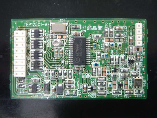
Inside pictures 【TRANSMITTING UNIT inside pictures】 《antenna part with case》 《front side》《back side》 《antenna part》 RF unit RF unit 【RF unit inside pictures】 《front side》 ※without shield case 《back side》
Test Report
Test report No. : 30CE0008-YK-01-F-R1 Page : 2 of 23 Issued date : July 23, 2010 Revised date : September 15, 2010 FCC ID : YK4-JW9-8A2F0-00 UL Japan, Inc. Head Office EMC Lab. 4383-326 Asama-cho, Ise-shi, Mie-ken 516-0021 JAPAN Telephone : +81 596 24 8116 Facsimile : +81 596 24 8124 CONTENTS PAGE SECTION 1: Customer information··········································································································· 3 SECTION 2: Equipment under test (E.U.T.) ···························································································· 3 SECTION 3: Test specification, procedures & results ············································································· 4 SECTION 4: Operation of E.U.T. during testing······················································································ 7 SECTION 5: Conducted Emission·············································································································· 9 SECTION 6: Radiated emission (Electric Field Strength of Fundamental and Spurious Emission)10 SECTION 7: 20dB Bandwidth and Duty Cycle ······················································································11 APPENDIX 1: Photographs of test setup ································································································· 12 Conducted Emission .........................................................................................................................12 Radiated Emission ............................................................................................................................13 APPENDIX 2: Data of EMI test ················································································································· 14 Conducted Emission .........................................................................................................................14 Radiated Emission (Electric Field Strength of Fundamental and Spurious Emission) .....................16 20dB Bandwidth ...............................................................................................................................19 Duty Cycle ........................................................................................................................................20 APPENDIX 3:Test Instruments ················································································································· 23 Test report No. : 30CE0008-YK-01-F-R1 Page : 3 of 23 Issued date : July 23, 2010 Revised date : September 15, 2010 FCC ID : YK4-JW9-8A2F0-00 UL Japan, Inc. Head Office EMC Lab. 4383-326 Asama-cho, Ise-shi, Mie-ken 516-0021 JAPAN Telephone : +81 596 24 8116 Facsimile : +81 596 24 8124 SECTION 1: Customer information Company Name : YAMAHA MOTOR POWERED PRODUCTS CO., LTD. * Address : 322-1 Narutaki, Kakegawa, Shizuoka, 436-0085 Japan Telephone Number : +81-537-21-0950 Facsimile Number : +81-537-21-0951 Contact Person : Atsushi Uchiyama *Remarks: YAMAHA MOTOR POWERED PRODUCTS CO., LTD. designates Tateyama Kagaku Industry Co., Ltd. as manufacturer of the product (TRANSMITTING UNIT). SECTION 2: Equipment under test (E.U.T.) 2.1 Identification of E.U.T. Type of Equipment : TRANSMITTING UNIT Model No. : JW9-8A2F0-00 Serial No. : Refer to Section 4, Clause 4.2 Rating : AC 120V/60Hz Receipt Date of Sample : June 11, 2010 Country of Mass-production : Japan Condition of EUT : Engineering prototype (Not for Sale: This sample is equivalent to mass-produced items.) Modification of EUT : No Modification by the test lab 2.2 Product Description Model No: JW9-8A2F0-00 (referred to as the EUT in this report) is the TRANSMITTING UNIT. Feature of EUT: EUT is the data transfer unit. It conducts radio communication (transmitting and receiving) with BASE ASSY and TERMINAL UNIT. Clock frequency(ies) in the system : CPU Main: 9.8034MHz, RF reference clock: 14.7456MHz Equipment Type : Transceiver Frequency of Operation : 916.2204MHz, 918.0636MHz, 921.7500MHz, 923.5932MHz Frequency Shift : 64kHz Type of Modulation : FSK Antenna Type : Monopole Antenna Antenna Gain : 2dBi Antenna Connector Type : SMA Power Supply (Inner) : DC 3.3V Test report No. : 30CE0008-YK-01-F-R1 Page : 4 of 23 Issued date : July 23, 2010 Revised date : September 15, 2010 FCC ID : YK4-JW9-8A2F0-00 UL Japan, Inc. Head Office EMC Lab. 4383-326 Asama-cho, Ise-shi, Mie-ken 516-0021 JAPAN Telephone : +81 596 24 8116 Facsimile : +81 596 24 8124 SECTION 3: Test specification, procedures & results 3.1 Test Specification Test Specification : FCC Part15 Subpart C: 2010, final revised on January 22, 2010 and effective March 1, 2010 Title : FCC 47CFR Part15 Radio Frequency Device Subpart C Intentional Radiators Section 15.207 Conducted limits Section 15.249 Operation within the bands 902-928MHz, 2400-2483.5MHz, 5725-5875MHz and 24.0-24.25GHz 3.2 Procedures and results No. Item Test Procedure Specification Deviation Worst margin Results 1 Conducted Emission ANSI C63.4:2003 7. AC powerline conducted emission measurements Section 15.207(a) N/A [QP] 20.6dB (0.19992MHz, N) [AV] 27.6dB (0.26931MHz, N) Complied 2 Electric Field Strength of Fundamental Emission ANSI C63.4:2003 13. Measurement of intentional radiators Section 15.249(a)(e) N/A 0.2dB (916.220MHz, Vertical, QP) Complied 3 Electric Field Strength of Spurious Emission ANSI C63.4:2003 13. Measurement of intentional radiators Section 15.205(a)(b) Section 15.209(a) Section 15.249(a)(d)(e) N/A 1.4dB (1847.186MHz, Vertical, PK with Duty factor) Complied 4 20dB Bandwidth ANSI C63.4:2003 Reference N/A N/A N/A 5 Frequency Tolerance ANSI C63.4:2003 Section 15.249(b) N/A N/A N/A *1) Note: UL Japan, Inc.’s EMI Work Procedures No.QPM05 and QPM15. *1) The test is not required since this EUT does not operate with 24.05GHz to 24.25GHz. *In case any questions arise about test procedure, ANSI C63.4: 2003 is also referred. FCC 15.31 (e) This EUT provides stable voltage (DC 3.3V) constantly to RF part …
Text truncated - open the document above for the full version.
Test Report
Test report No. : 30CE0008-YK-01-F-R1 Page : 14 of 23 Issued date : July 23, 2010 Revised date : September 15, 2010 FCC ID : YK4-JW9-8A2F0-00 UL Japan, Inc. Head Office EMC Lab. 4383-326 Asama-cho, Ise-shi, Mie-ken 516-0021 JAPAN Telephone : +81 596 24 8116 Facsimile : +81 596 24 8124 APPENDIX 2: Data of EMI test Conducted Emission DATA OF CONDUCTED EMISSION TEST UL Japan, Inc. Head Office EMC Lab. No.2 Semi Anechoic Chamber Date : 2010/06/16 Company : TATEYAMA KAGAKU INDUSTRY CO.,LTD. Report No. : 30CE0008-YK-01 Kind of EUT : TRANSMITTING UNIT Power : AC 120V / 60Hz Model No. : JW9-8A2F0-00-0 Temp./Humi. : 24deg.C / 69% Serial No. : 1 Engineer : Katsunori Okai Mode / Remarks : Tx 916.2204MHz LIMIT : FCC15.207 QP FCC15.207 AV CHART:WITH FACTOR,Peak hold data. CALCULATION:RESULT[dBuV]=READING[dBuV]+C.F[dB](LISN LOSS+CABLE LOSS) Except for the above table : adequate margin data below the limits. Frequency[Hz] [dBuV]<< QP/AV DATA >> L:QP:AV N:QP:AV .15M30M.2M.3M.5M.7M1M2M3M5M7M10M20M 0 10 20 30 40 50 60 70 80 Frequency Reading LevelReading LevelCorr.ResultsResultsLimitLimitMarginMargin PhaseComment Frequency QPAVFactorQPAVQPAVQPAVPhaseComment [MHz][dBuV][dBuV][dB][dBuV][dBuV][dBuV][dBuV][dB][dB] PhaseComment 0.1500013.1-2.313.326.411.066.056.039.645.0N 0.1999229.711.213.343.024.563.653.620.629.1N 0.2693123.110.213.336.423.561.151.124.727.6N 0.3329818.25.913.331.519.259.449.427.930.2N 0.6294319.23.513.432.616.956.046.023.429.1N 18.7680510.40.715.125.515.860.050.034.534.2N 0.1500012.0-2.413.325.310.966.056.040.745.1L 0.2008126.37.113.339.620.463.653.624.033.2L 0.2663120.47.213.333.720.561.251.227.530.7L 0.3312516.24.513.329.517.859.449.429.931.6L 0.6364418.64.413.432.017.856.046.024.028.2L 18.7480511.72.115.126.817.260.050.033.232.8L Test report No. : 30CE0008-YK-01-F-R1 Page : 15 of 23 Issued date : July 23, 2010 Revised date : September 15, 2010 FCC ID : YK4-JW9-8A2F0-00 UL Japan, Inc. Head Office EMC Lab. 4383-326 Asama-cho, Ise-shi, Mie-ken 516-0021 JAPAN Telephone : +81 596 24 8116 Facsimile : +81 596 24 8124 Conducted Emission Test place Head Office EMC Lab. No.2 Semi Anechoic Chamber Report No. 30CE0008-YK-01 Date 06/16/2010 Temperature/ Humidity 24 deg. C. / 69% Engineer Katsunori Okai Mode Transmitting mode 916.2204MHz 918.0636MHz 923.5932MHz Y scale [dBuV] Chart N L Test report No. : 30CE0008-YK-01-F-R1 Page : 16 of 23 Issued date : July 23, 2010 Revised date : September 15, 2010 FCC ID : YK4-JW9-8A2F0-00 UL Japan, Inc. Head Office EMC Lab. 4383-326 Asama-cho, Ise-shi, Mie-ken 516-0021 JAPAN Telephone : +81 596 24 8116 Facsimile : +81 596 24 8124 Radiated Emission (Electric Field Strength of Fundamental and Spurious Emission) Test place Head Office EMC Lab. No.2 Semi Anechoic Chamber Report No. 30CE0008-YK-01 Date 06/15/2010 Temperature/ Humidity 23 deg. C. / 67% 22 deg. C./ 60% Engineer Katsunori Okai Hiroyuki Furutaka (Above 1GHz) (Below 1GHz) Mode Transmitting mode, 916.2204MHz QP or PK FrequencyDetectorAntLossGainDutyLimit FactorFactor [MHz]HorVer[dB/m][dB][dB][dB]HorVer[dBuV/m ]HorVer 39.39 QP22.93615.26.828.7-16.229.340.023.810.7 50.96 QP22.932.811728.7-12.222.140.027.817.9 404.234 QP21.421.917.59.428.3-20.020.546.026.025.5 536.832 QP22.422.218.69.928.8-22.121.946.023.924.1 700.700 QP22.121.920.410.528.6-24.424.246.021.621.8 902.000 QP21.621.522.511.228-27.327.246.018.718.8 916.220 QP78.287.722.611.327.9-84.293.793.99.70.2 1832.441 PK54.057.826.33.032.5-50.854.673.923.119.3 2748.661 PK45.646.127.33.432.3-44.044.573.929.929.4 3664.882 PK43.843.328.33.931.8-44.243.773.929.730.2 4581.102PKNSNS------73.9 -- 5497.322PKNSNS------73.9 -- 6413.543PKNSNS------73.9 -- 7329.763PKNSNS------73.9 -- 8245.984PKNSNS------73.9 -- 9162.204PKNSNS------73.9 -- Result = Reading + Ant Factor + Loss (Cable+Attenuator+Filter) - Gain(Amprifier) PK with Duty factor FrequencyDetectorAntLossGainDutyLimit FactorFactor [MHz]HorVer[dB/m][dB][dB][dB]HorVer[dBuV/m ]HorVer 1832.441 PK54.057.826.33.032.5-2.947.951.753.96.02.2 2748.661 PK45.646.127.33.432.3-2.941.141.653.912.812.3 3664.882 PK43.843.328.33.931.8-2.941.340.853.912.613.1 4581.102 PKNSNS----2.9--53.9-- 5497.322 PKNSNS----2.9--53.9-- 6413.543 PKNSNS----2.9--53.9-- 7329.763 PKNSNS----2.9--53.9-- 8245.984 PKNSNS----2.9--53.9-- 9162.204 PKNSNS----2.9--53.9-- Result = Reading + Ant Factor + Loss (Cable+Attenuator+Filter) - Gain(Amprifier) + Duty factor (Refer to Duty factor data sheet) *Other frequency noises omitted in this report were not seen or had enough margin (more than 20dB). *NS: No Signal Margin [dB] Margin [dB] ReadingResult Reading [dBuV] Result [dBuV/m] [dBuV][dBuV/m] * The test above 1GHz was performed with PK detect. Average emission measurements were calculated with PK detect and Duty cycle factor. * Duty Factor was calculated with the assumption of the worst condition in 100msec. * The noise measured with PK detect was pulse emission. Test report No. : 30CE0008-YK-01-F-R1 Page : 17 of 23 Issued date : July 23, 2010 Revised date : September 15, 2010 FCC ID : YK4-JW9-8A2F0-00 UL Japan, Inc. Head Office EMC Lab. 4383-326 Asama-cho, Ise-shi, Mie-ken 516-0021 JAPAN Telephone : +81 596 24 8116 Facsimile : +81 596 24 8124 Radiated Emission (Electric Field Strength of Fundamental and Spurious Emission) Test place Head Office EMC Lab. No.2 Semi Anechoic Chamber Report No. 30CE0008-YK-01 Date 06/15/2010 Temperature/ Humidity 23 deg. C. / 67% 22 deg. C. / 60% Engineer Katsunori Okai Hiroyuki Furutaka (Above 1GHz) (Below 1GHz) Mode Transmitting mode, 918.0636MHz QP or PK FrequencyDetectorAntLossGainDutyLimit FactorFactor [MHz]HorVer[dB/m][dB][dB][dB]HorVer[dBuV/m]HorVer 38.760 QP23.436.415.46.828.7-16.929.940.023.110.1 50.980 QP23.233.111.07.028.7-12.522.440.027.517.6 348.934 QP21.621.815.99.128.1-18.518.746.027.527.3 404.234 QP22.522.117.59.428.3-21.120.746.024.925.3 536.832 QP22.622.518.69.928.8-22.322.246.023.723.8 700.700 QP22.32220.410.528.6-24.624.346.021.421.7 918.064 QP79.487.022.611.327.9-85.493.093.98.50.9 1836.127 PK54.157.626.33.032.5-50…
Text truncated - open the document above for the full version.
Test Setup Photos
Test report No. : 30CE0008-YK-01-F-R1 Page : 12 of 23 Issued date : July 23, 2010 Revised date : September 15, 2010 FCC ID : YK4-JW9-8A2F0-00 UL Japan, Inc. Head Office EMC Lab. 4383-326 Asama-cho, Ise-shi, Mie-ken 516-0021 JAPAN Telephone : +81 596 24 8116 Facsimile : +81 596 24 8124 APPENDIX 1: Photographs of test setup Conducted Emission Photo 1 Photo 2 Test report No. : 30CE0008-YK-01-F-R1 Page : 13 of 23 Issued date : July 23, 2010 Revised date : September 15, 2010 FCC ID : YK4-JW9-8A2F0-00 UL Japan, Inc. Head Office EMC Lab. 4383-326 Asama-cho, Ise-shi, Mie-ken 516-0021 JAPAN Telephone : +81 596 24 8116 Facsimile : +81 596 24 8124 Radiated Emission Photo 1 Photo 2
Contact Information
Applicant
Atsushi Uchiyama(Head manager of the Golf-car development Div.)
Technical Contact
UL Japan, Inc.Mitsuru Fujimura
[email protected]81-596-24-8116
4383-326 Asama-cho, Ise-shi, · Mie-ken · Japan
Test Firm
UL Japan, Inc. Head office EMC Lab.Tetsuya Hashimoto
Technical Specifications
| # | Rule Parts | Frequency Range | Power Output |
|---|---|---|---|
| 4 | 15C | 923.5932 MHz - 923.5932 MHz | - |
Other Applications from YAMAHA MOTOR POWERED PRODUCTS CO., LTD.
YK4-JW9-85560-00
Sep 15, 2010BASE ASSY
Equipment Class
DXT - Part 15 Low Power Transceiver, Rx Verified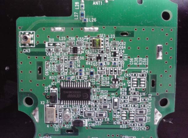
YK4-JW9-85579-00
Sep 15, 2010TERMINAL UNIT
Equipment Class
DXT - Part 15 Low Power Transceiver, Rx Verified