YK7080508251CXXXMRFBE Module
RFI Americas, Inc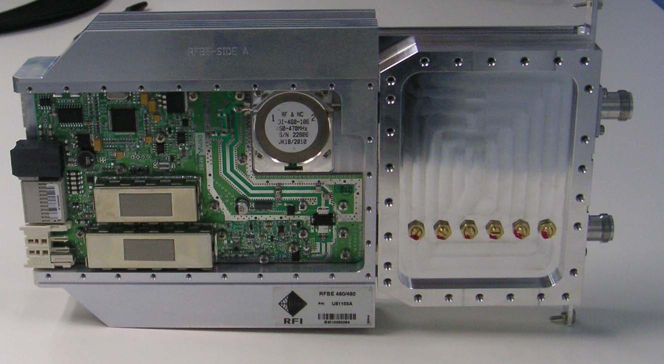
Click to zoom
Application Details
- Equipment Class
- TNB - Licensed Non-Broadcast Station Transmitter
- Date of Grant
- Aug 23, 2010
- Application Purpose
- Original Equipment
- Date of Application
- Aug 23, 2010
- Equipment Note
- RFBE Module
- Frequency Range
- 809.00000000 - 824.00000000
- Company
- RFI Americas, Inc
- Country
- United States
Documents & Files
Document Text
Text extracted from the exhibit documents filed with the FCC. Open a document above to read the original.
Users Manual
Australian Provisional Patent Application No. 2009905291 User’s Manual Rebroadcast Repeater/Booster. Base Line release 1.0 DSPbR Series TM DSPbR Series – User’s Manual Document Number 00000.B Page 2/75 Notice The information contained in this document is subject to change without notice. RF Industries Pty Ltd. makes no warranty of any kind with regard to this material, including but not limited to, the implied warranties of merchantability and fitness for a particular purpose. RF Industries Pty Ltd shall not be liable for errors contained herein or for incidental or consequential damages in connection with the furnishing, performance or use of the material. All information contained in this manual has been reviewed. RF Industries Pty Ltd accepts no responsibility or liability for any omissions, errors or misinterpretation of information. 2010, RF Industries Pty Ltd. All rights reserved. Reproduction, adaptation or translation without prior written permission is prohibited except as allowed under copyright laws. For further information or help with this product contact your nearest RFI sales office or through the following; Within Australia dial: 1300 000 RFI (1300 000 734) International: +61 7 3621 9400 Sales email: [email protected] Technical support email: [email protected] Note: Operation of this equipment pursuant to Part 90 of the FCC rules should be identified by selecting “Part 90 Operation” in the GUI Channel Configuration screen, thereby limiting the per-channel RF output power and preventing frequency-translating operation. Note: This device complies with Part 15 of the FCC Rules. Operation is subject to the following two conditions; (1) This device may not cause harmful interference, and (2) This device must accept any interference received, including interference that may cause undesired operation. The user is cautioned that changes and/or modifications not approved by the responsible party could void the user’s authority to operate the equipment. Note: This equipment has been tested and found to comply with the limits for a Class A digital device, pursuant to Part 15 of the FCC Rules. These limits are designed to provide reasonable protection against harmful interference when the equipment is operated in a commercial environment. This equipment generates, uses, and can radiate radio frequency energy and, if not installed and used in accordance with the instruction manual, may cause harmful interference to radio communications. Operation of this equipment in a residential area may cause harmful interference in which case the user will be required to correct the interference at their own expense. DSPbR Series – User’s Manual Document Number 00000.B Page 3/75 Table of Contents Chapter Page 1 General 1.1 Used abbreviations 1.2 Tables and Figures List 1.3 Health and Safety warnings 1.4 About RF Industries Pty Ltd 1.5 RFI Contact Details 2 Introduction 2.1 Application 2.2 Product Overview 2.3 Product Specifications 3 Functional Description 3.1 General 3.2 Sub Rack Frame 3.3 Modules 3.3.1 PSU Inlet Module 3.3.2 PSU - Power Supply Module 3.3.3 CSC – Central System Controller Module 3.3.4 Ref Gen + Aux – Reference Generator Module 3.3.5 DSP – Digital Signal Processor Module 3.3.6 RFFE – RF Front End Module 3.3.7 RFBE – RF Back End Module 3.3.8 BPFM – Band Pass Filter Module 3.3.9 CXXX-8 – 8Ch Combiner Unit. 3.3.10 TLM – Through Line Module 3.4 Band & channel configurations 3.5 Internal RFBE combining 3.6 Available frequency bands 3.7 System expansion 4 Installation 4.1 Unpacking 4.2 Mechanical 4.3 Earthing and Electrical 4.4 Lightning Protection 4.5 Antenna Installation 4.6 External / Internal Alarm Interface DSPbR Series – User’s Manual Document Number 00000.B Page 4/75 5 Start – Up 5.1 Connectivity 5.2 Ethernet Connection Set up 5.2.1 Webb Browser GUI (Graphical User Interface) 5.2.2 IP Address 5.2.3 Log in page 5.2.4 GUI Tree 5.2.5 Introduction 5.2.6 Status pages 5.2.7 Configure pages 5.2.8 Maintenance 5.2.9 Logout 5.3 Ref Gen Module – GPS/Ext 10MHz Ref/Int 10MHz Ref/Cell Modem 5.4 CSC Module - Front Panel LCD Display, Mode Buttons and LED’s 5.5 Uploading and Downloading Firmware 6. Temperature Management 7. Alarming and Supervision 8. Firmware User’s Licence Agreement. 9. Maintenance 9.1 Access 9.2 Module replacement 9.3 PSU resettable and replaceable fuses. 9.4 Fans and fan filters 9.5 RF input and output port identification 10. Ancillary equipment and spares part numbers 11. Frequently Asked Questions 12. Appendix A Slot architecture configuration options Revision History Name Revision Date Hedley Boyd-Moss A 10/06/2010 Scott Alford B 10/7/2010 DSPbR Series – User’s Manual Document Number 00000.B Page 5/75 1. GENERAL 1.1 Used abbreviations ALC Automatic Level Control BPF Band Pass Filter BPFM Band Pass Filter Module BTS Base Transceiver Station CAN Controller Area Network CAT5/6 Category 5 or 6 (Ethernet cable – standard wiring) CLI Command Line Interface CSC Central System Controller DL Downlink DSP Digital Signal Processor DSPbR Digital Signal Processor based Repeater ETSI European Telecommunication Standards Institute GPS Global Positioning System GUI Graphical User Interface IF Intermediate Frequency MS Mobile Station PSU Power Supply Unit Ref Gen Reference Generator Rev Revision RF Radio Frequency RFBE Radio Frequency Back End RFFE Radio Frequency Front End RSSI Receive Signal Strength Indication RTC Real Time Clock RU Rack Units Rx Receiver TLM Through Line Module Tx Transmitter UL Uplink VSWR Voltage Standing Wave Radio 1.2 Tables and Figures List Table 1 - Abbreviations DSPbR Series – User’s Manual Document Number 00000.B Page 6/75 Tables Page 1 Abbreviations. 2 DSPbR Generic Product Specifications 3 8-Ch Internal Combiner Filter, per Channel Max Power Ratings 4 dBm to RF Power in Watts – Cross Reference 5 Ancillary Equipment and Spare Part Numbers 6 Recommended Spares Listing Figures Page 1 Typical DSPbR Functional Block Diagram 2 DSPbR Front View 3 DSPbR Rear Vie…
Text truncated - open the document above for the full version.
Users Manual
DSPbR Series – User’s Manual Document Number 00000.B Page 21/75 number and if there are corresponding RFFE and RFBE board configuration files from a previous module or saved configuration, the inserted modules configuration will be updated by the CSC accordingly. A label bearing the respective module’s model number, version and serial number identifies each module. This label is adhered to the side of the module and is not visible without removing the module from the slot. A user definable removable yellow plastic labelling system has been provided on the external surface of the BPFM bolted to the RFFE and RFBE modules to assist the user to identify allocated ports once the user has configured the DSPbR using the web browser. 3.3.1 PSU Inlet Module The PSU inlet module is a power-conditioning module. There are three versions of this module; 240VAC, 110VAC and a 48VDC. Both the 240AC and 110VAC inlet modules have an IEC320-C19 socket into which the provided and respective mains power cord is plugged. The inlet module provides a degree of mains surge protection. Although the AC PSU module accommodates an input voltage range from 110V to 240V, the appropriate 110V or 240V AC inlet module has to be fitted. 3.3.2 PSU Module The PSU module is designed as modular and removable from the front of the repeater. Preceding the AC PSU is the appropriate inlet module. Currently, two PSU modules are available, 110VAC/60Hz to 240 VAC/50Hz AC and a 48VDC version. To remove the PSU module, unscrew the six front mount screws from the front of the unit as illustrated in Figure-4. Figure 4 – DSPbR AC PSU DSPbR Series – User’s Manual Document Number 00000.B Page 22/75 When removing or replacing the PSU, ensure to disconnect or connect the in-line plug / socket into the inlet module. There are three replaceable inverter fuses located within the AC PSU module and in order to check or replace any of these fuses, the PSU has to be unscrewed from the sub rack frame as previously illustrated in Figure-4, lever forward on the guide rails using the available handle far enough to access the fuse holders as illustrated in Figure-5. All three fuses are identical and listed under the DSPbR part number reference list. An AC mains supply resettable circuit breaker is mounted on the front of the DSPbR PSU between the two fans. Should this AC resettable circuit breaker “pop-out” under operational conditions; a PSU failure alarm will be activated. It is strongly recommended that an investigation be made prior to resetting the circuit breaker as to the possible reasons why the circuit breaker was activated. 3.3.3 CSC – Central Systems Controller Module The Central System Controller module is located at the front of the DSPbR and is positioned on the extreme left hand side as illustrated in Figure-6. An LCD display, a power and two alarm LED’s, mode change button, USB Type B, TCP/IP RJ45, RS232 socket and CAN bus RJ11 socket are located on face of the CSC module. DSPbR configuration and diagnostics for all modules is via the CSC module. Figure 5 – AC PSU fuse location.
Users Manual
DSPbR Series – User’s Manual Do cument Number 00000.B Page 23/ 75 Ther e are two versions of the CSC module, “master” and “slave”. The fundamental difference being the master CSC has a single RJ11 connector to facilitate connectivity into the inter sub rack CAN bus. The slave CSC module has two RJ11 connectors to facilitate daisy chaining should additional sub rack frames require connection. The master CSC has an onboard back up battery, which provides power to the processor and cell modem to enable the sending of an appropriate alarm. The processor stores system configuration files and is able to restore previous configuration settings to a newly plugged in module. This battery is connected or disconnected via the web browser interface. Whilst connected, the battery is conditioned through an intelligent charger. The internal battery is hardwired into the module and does not require field maintenance or replacement. 3.3.4 Ref Gen + Aux – Reference Generator Module Located at the rear of the rack on the extreme right hand side (looking at the back of the rack from the rear), the Ref Gen + Aux module is not optional. The Ref Gen + Aux module provides interconnectivity to and from optional signal reference sources such as GPS and an external 10MHz signal. When a GPS signal is required to discipline the reference generator clock frequency, an active GPS antenna must be connected to this input. The output voltage on this connector is 6VDC rated at 0.5A The “EXT REF” SMA Female connector is used to lock the reference generator to an external 10MHz reference. The required stability of this reference is +/- 3PPM with a nominal input signal level of 0dBm (0.22V Figure 6 – CSC Controller
Users Manual
DSPbR Series – User’s Manual Document Number 00000.B Page 24/75 RMS on 50 Ohms). The presence of the external reference above a certain level will lock the Ref Gen clock frequency to that reference. The “REF MON” SMA Female connector provides a 10MHz low impedance reference signal output at 0dBm (nominal). The output is daisy chained through each Ref Gen + Aux module that requires the clock reference. When daisy chained the Ref Gen + Aux modules will buffer the 10 MHz reference prior to forwarding onto the next Ref Gen + Aux module. Where more than one sub rack frame is required a Ref Gen + Aux (without the cell modem option) has to be included in each additional sub rack frame. The master Ref Gen + Aux module should have the cell modem option fitted if required. Only one cell modem is required in the master sub rack frame to communicate the alarms from the Master and slave sub rack frames. 3.3.5 DSP – Digital Signal Processor Module A DSP module is partitioned into Side “A” and Side “B”. Channel and multi-band independent a single DSP board Side “A” will service up to 4 bi-direction carriers (uplink and downlink) in two bands. With both sides populated a DSP module is capable of processing up to 8 bi-directional channels in 3 bands. The DSP module fits into slot 10. This is the only slot allocated to the DSP module in the motherboard architecture. The DSP module does not require a tool to remove it once the screw fasteners have been fully released, there are two ejector lever handles which assist in its removal from the sub rack frame. Figure 7 – Ref Gen + Aux Module
Users Manual
DSPbR Series – User’s Manual Document Number 00000.B Page 25/75 A DSP board in side “A” is wired to take inputs from RFFE boards in slots 9 & 8 and drives RFBE boards in slots 1, 2, 5 & 6. A DSP board in side “B” takes inputs from RFFE boards in slot 7 and drives RFBE boards in slots 3, 4, 7 & 8. The DSP module can be removed and replaced whilst the DSPbR is powered, however the functionality will cease, inhibiting the signal path between RFFE and RFBE’s whilst a DSP module is unplugged. An arrow with the letters “UP” on the rear face indicates the module orientation. 3.3.6 RFFE – RF Front End Module An RFFE module is partitioned into side “A” and side “B”. Two RFFE boards are fitted into an RFFE module. The RFFE boards can be in different bands, however the BPFM fasted to the RFFE module must have the corresponding Side “A” and Side “B” band pass filters. The motherboard architecture accommodates up to six RFFE boards (three modules). The 1 st slot allocation for the RFFE module is slot 9 (please note that slot 9 is dedicated to an RFFE slot only) followed by slots 8 and 7 respectively. The frequency bandwidth of each RFFE is a contiguous 20MHz. One RFFE can feed any number of corresponding channelized RFBE’s. This is true for bi-directional uplink and downlink configurations. Although the individual channel frequency and its characteristics within an RFFE band is adjustable, the RFFE band is fixed and is not adjustable. A different RFFE module is required for each 20MHz band. Figure 8 – DSP Module
Users Manual
DSPbR Series – User’s Manual Document Number 00000.B Page 26/75 Channel programmability Channel programming is done via the web browser GUI interface – Refer to chapter 5.2.7 Level 1: User name and password access via the web browser GUI interface displays only status of the channel configuration. Level 2: User name and password access via the web browser GUI interface facilitates status display and channel configuration capability. Typical hardware configuration examples RFFE 410-410 module is configured with an RFFE 400-420MHz board in side “A” and the same 400-420MHz RFFE board in side “B”. An RFFE 815-860 module is configured with an RFFE 805-825MHz board in side “A” and an 850-870MHz RFFE board in side “B”. 3.3.7 RFBE – RF Back End Module An RFBE module is partitioned into side “A” and side “B”. Two RFBE boards are fitted into an RFBE module. The RFBE boards can be in different bands, however the BPFM fastened to them must have the corresponding side “ A” and side “B” band pass filters. Figure 9 – RFFE & BPFM bolted together RFFE BPFM DSPbR Series – User’s Manual Document Number 00000.B Page 27/75 The motherboard architecture accommodates up to sixteen RFFE boards (eight modules). A DSP board in side “A” takes inputs from RFFE boards in slots 9 & 8 and drives RFBE boards in slots 1, 2, 5 & 6. A DSP board in side “B” takes inputs from RFFE boards in slot 7 and drives RFBE boards in slots 3, 4, 7 & 8. The slot allocations for the DSPbR reflect the DSP architecture where the first four RFFE channels (2 modules) are allocated to slots 1 and 2. The next four RFFE channels, which correspond to RFBE modules 3 and 4, will be accommodated in slots 5 and 6. Correspondingly; in a bi-directional configuration the RFBE modules for the alternative direction will accommodate slots 3 and 4 and then 7 and 8. The illustration of form and the bolting together of the BPFM to the RFFE in Figure 9 is the same for the RFBE. Although the individual channel frequency and its characteristics within an RFBE band is adjustable, the RFBE band is fixed. RFBE modules are band specific. Channel programmability Channel programming is done via the web browser GUI interface – Refer to chapter 5.2.7 Level 1: User name and password access via the web browser GUI interface displays only status of the channel configuration. Level 2: User name and password access via the web browser GUI interface facilitates status display and channel configuration capability. Typical configuration examples An RFBE 410-410 module is configured with an RFBE 400-420MHz board in side “A” and the same 400- 420MHz RFBE board in side “B”. An RFBE 815-860 module is configured with an RFBE 805-825MHz board in side “A” and an 850-870MHz RFBE board in side “B”. Output power level settings When configuring the RFBE via the GUI, the adjustable RF output power level is referenced to dBm and is the output level of the RFBE only and not the output power level at the external connector at the rear of the DSPbR. The level is adjustable in 1dB increments from +30dBm to +46dBm (+/- 0.5dB) for frequencies from 400 to 490MHz and +30 to +43dBm in 1dB increments for the 805 to 870MHz Frequency Range. Although the drop DSPbR Series – User’s Manual Document Number 00000.B Page 28/75 down menu will indicate a level of up to +46dBm the level remains constant at +43dBm as the maximum. Refer to Table 3. GUI Channel Configuration Overview page When an 8-Ch combiner filter unit has been fitted in either the uplink or downlink or both, the provided tick box needs to be activated “per channel” feeding through the 8-Ch combiner filter unit in order for the maximum output power to be auto-adjusted. This will effectively reduce the maximum output power setting of the RFBE to + 40dBm from +46dBm which will cater for up to 6 combined channels. Should the user wish to manually adjust the maximum output power level, Table 3 will indicates the MAXIMUM output power level setting permissible without causing damage to the 8-Ch Combiner Filter Unit. RFBE Max Output power setting via GUI 805-870MHz Freq Range Approx Output Power at output of 8Ch combiner filter unit Filter tick box activated Number of carriers RFBE Max Output power setting via GUI 400-490MHz Freq Range Indicated Actual 400-490MHz 806-870MHz 2 46dBm 46dBm 43dBm 34.5dBm 31.5dBm 3 46dBm 46dBm 43dBm 34.5dBm 31.5dBm 4 44dBm 43dBm 43dBm 32.5dBm 31.5dBm 5 42dBm 42dBm 42dBm 30.5dBm 30.5dBm 6 40dBm 40dBm 40dBm 28.5dBm 28.5dBm 7 39dBm 39dBm 39dBm 27.5dBm 27.5dBm 8 38dBm 38dBm 38dBm 26.5dBm 26.5dBm Table 3 – 8-Ch Internal Combiner Filter, per Carrier Max Power Settings 8-Ch Combiner Filter “Tick DSPbR Series – User’s Manual Document Number 00000.B Page 29/75 Notes: 1) Approximate loss through combiner filter unit for all bands is 11.5dB 2) Duty Cycle assumption per channel 100% 3) All carriers are to be set to the same level As indicated in Table 3, an additional 11.5dB of loss has to be added to the RFBE RF output power figure to get an indication of the output of the 8-Ch combiner filter unit. The output power level has then to be adjusted negatively by 0.25dB if it is fed through a TLM or 1.2dB through the standard BPFM. dBm Watts dBm Watts dBm Watts 0 1.0 mW 16 40 mW 32 1.6 W 1 1.3 mW 17 50 mW 33 2.0 W 2 1.6 mW 18 63 mW 34 2.5 W 3 2.0 mW 19 79 mW 35 3.2 W 4 2.5 mW 20 100 mW 36 4.0 W 5 3.2 mW 21 126 mW 37 5.0 W 6 4 mW 22 158 mW 38 6.3 W 7 5 mW 23 200 mW 39 8.0 W 8 6 mW 24 250 mW 40 10 W 9 8 mW 25 316 mW 41 13 W 10 10 mW 26 398 mW 42 16 W 11 13 mW 27 500 mW 43 20 W 12 16 mW 28 630 mW 44 25 W 13 20 mW 29 800 mW 45 32 W 14 25 mW 30 1.0 W 46 40 W 15 32 mW 31 1.3 W 47 50 W 3.3.8 BPFM – Band Pass Filter Module The DSPbR BPFM (Band Pass Filter Module) is band specific across the pre-determined bandwidth of the respective RFBE or RFFE. The BBFM is fitted and bolted into the output of the RFBE and input of the RFFE and is considered as an extension to the respective RFFE or RFBE module. Prior to assembly into a nominated slot, the BF…
Text truncated - open the document above for the full version.
Users Manual
DSPbR Series – User’s Manual Document Number 00000.B Page 31/75 3.4.10 TLM - Through Line Module Where external combining is required, which would typically be in the output channels of the downlink, and sufficient band pass filtering is provided within an optional external combiner, then a TLM can be bolted to the output of the RFBE instead of the BPFM. The form dimensions and connector arrangement of the TLM is the same as the BPFM. It is very important to provide band pass filtering in the external combiner equivalent or better than the filtering provided by the BPFM in order to maintain the required frequency spectral purity. 3.5 Band and Channel Configurations The DSPbR architecture facilitates band and channel flexibility with in-field upgradability. At the rear of the DSPbR sub rack frame are 10 slot apertures numbered sequentially from the left. SIDE ASIDE B DSP Ref GEN Power Input Slot 1Slot 9Slot 10Slot 6Slot 4Slot 3Slot 7Slot 8Slot 5Slot 2 View from rear of DSPbR Figure 12 – Slot Allocation Architecture Figure 11 – CXXX-8. 8-Ch Internal Combiner Filter Unit. DSPbR Series – User’s Manual Document Number 00000.B Page 32/75 Slot allocation architecture; Slots 1-6 allocated to RFBE’s only. Slots 9 allocated to RFFE only. Slots 7 & 8 allocated to either RFFE’s or RFBE’s. Slot 10 allocated to a DSP module. Typically slots 1-4 or 5-8 are used for an 8-Ch Internal combiner filter unit, however the combiner unit can fit across any 4 continuous RFBE slot block. RFBE modules can be configured such that side “A” is an uplink channel and side “B” is a downlink channel. When RFBE modules are configured in this way, the use of an internal combiner is not possible. Alternatively, RFBE modules can be configured with both side “A” and side “B” as uplink or downlink. This configuration option along with the corresponding slot block allocation permits the fitting of the internal combiner unit. Refer to Appendix “A” - Single Sub Rack Frame, DSPbR Slot Architecture – Typical Configurations. 3.6 Internal up link and down link RFBE combining Internal RFBE output combining of uplink and or downlink channels is optional, however the slot and uplink / downlink configuration has to be in accordance with the following simple rules. Rule 1. Both side “A” and side “B” within the RFBE module have to be configured as either uplink or downlink RFBE boards. Rule 2. Combined channels must occupy 4 contiguous slots, i.e. slots 1-4, 3-6 or 5-8. The 8-channel combiner filter unit uses a hybrid coupler technique to cater for combining frequencies that are adjacent or at any frequency within the allocated 20MHz bandwidth. Isolators and a band pass filter are incorporated within the combiner unit supporting good transmitter combining engineering practices. The 8-channel combiner filter unit fits directly into the back of the RFBE modules, effectively replacing the individual BPF modules at the outputs of the RFBE’s. The N female single output connector is accessible from the rear of the unit. Caution must be taken when touching the combiner module from the rear when in service as heat is likely to have been generated through this combining technique. Both uplink and or downlink output combining is possible within a single sub rack frame. The 8-Channel internal combiner has a single output and is not tuneable. DSPbR Series – User’s Manual Document Number 00000.B Page 33/75 Should this style of combining not be suitable for an application, external combining is recommended. When internal combining is not required, each RFBE module will be bolted to a corresponding BPFM, where the output N female connectors for both boards are presented at the rear of the sub rack. 3.7 Frequency Bands RFFE, RFBE, BPFM and 8-Ch combiner units are available for the following bands; 400-420MHz, 450-470MHz, 470-490MHz, 805-825MHz, 850-870MHz RFI will add additional frequency bands to this product series under our product development program. Please consult with our offices should there be a specific frequency range that you would be interested in which has not been listed. 3.8 System Expansion The DSPbR is expandable once the available slots have been utilised in a single sub rack frame. This is achieved by daisy chaining additional sub rack frames. Primarily, the CAN bus is extended to the required additional sub frame racks where the first rack would be nominated as the “Master” sub rack. Following sub racks are referred to as “Slaves”. This expandability accommodates additional bands and channels not possible utilising a single sub rack frame. The scope of this user manual does not cover DSPbR sub rack expansion in detail. Systems requiring additional sub racks frames in this manner will be provided project specific documentation. DSPbR Series – User’s Manual Document Number 00000.B Page 34/75 4. Installation 4.1 Unpacking The DSPbR is heavy and considered a two-man lift. The 19” sub rack frame will have been packed into a robust cardboard box container. All modules ordered with the initial order will have been fitted and fastened into the appropriate slots within the sub rack frame. The appropriate AC mains voltage power cord, Ethernet jumper cable and module extraction tool along with this User Manual in a hard and softcopy CD will have been packed into the same cardboard box container. There are no feet on the underside of the unit and therefore careful placement “right side up” on a flat surface prior to mounting is required. 4.2 Mechanical A single DSPbR sub rack frame will occupy 4RU of 19” rack height. The minimum un-obstructed depth required within the 19” rack, excluding the additional space required to fit cable terminated coaxial connectors is 439mm. Top and bottom and side covers of the sub rack frame are not required to be removed for field servicing and therefore we discourage any attempt to do so DSPbR Series – User’s Manual Document Number 00000.B Page 35/75 Figure 13 – DSPbR Dimensions Front View Figure 14 – DSPbR Dimensi…
Text truncated - open the document above for the full version.
Users Manual
DSPbR Series – User’s Manual Document Number 00000.B Page 36/75 Figure 15 – DSPbR Dimensions Left Hand Side View Figure 16 – DSPbR Dimensions Right Hand Side DSPbR Series – User’s Manual Document Number 00000.B Page 37/75 The DSPbR is designed to be mounted within a 19-inch rack frame within an indoor environment. Although the mechanical strength of the DSPbR sub rack frame is robust enough to contend with a maximum “all up” module load, any additional weight bearing adjustable mechanical supports such as angle brackets extending between the 19-inch front mounting frame and a rear frame would add strength to the support. There are many types of 19” rack cabinets and we suggest you consult with your 19” rack frame or cabinet supplier for appropriate weight support options. The DSPbR uses forced air cooling and requires good airflow from the front of the DSPbR where the two fans draw in cooler air and expel heated air at the rear. 19-inch rack cabinet ventilation must facilitate the unrestricted movement of cooler air from the front of the cabinet and the unrestricted movement of expelled hot air at the rear. The fan speeds are temperature controlled, alarm notification messages and hardwired state change critical alarm relay contacts will activate if the temperature exceeds safe operational limits. Figure 17 – DSPbR Dimensions Top View DSPbR Series – User’s Manual Document Number 00000.B Page 38/75 At maximum fan speed, which equates to the internal temperature edging up to +70 deg C, the fans will be running at full speed. This equates to an airflow volume for both fans of 880 cubic meters of air in an hour (equating to around 0.25 cubic meters in a second). Ensure unrestricted airflow to reducing differentiating high and low air pressure zones. Both fans have front panel accessible dust filters, which will require periodic cleaning. Please note that caution must be taken removing the fan covers and dust filters whilst the unit is operational as the fans may start up or be running. Although there is a protective guard to prevent fingers from accessing the fan blades, the suction and fan noise may startle the unknowing. The dust filters can be removed for cleaning by carefully levering off the plastic fan covers. No special tools are required and this can be done by hand. A mild soap wash and dry should be sufficient to clean the dust filters. Should they be perished in any way, please replace them. The fan dust filter part number is located under the part number section of this user’s manual. Different configurations will influence the weight of the DSPbR, It is however important to know that the DSPbR could weigh up to 38kgs, which is considered heavy and a two man lift. There are three handles located on the front panel of the unit of which only the two side handles are available for lifting the unit. The third handle is to be used only for the removal of the PSU and is marked with a label underneath the handle indicating that this handle is not to be used for lifting. 4.3 Earthing and Electrical Before proceeding with this chapter, if you have not done so, please read and familiarise yourself with the Health and Safety warnings in chapter 1.2 of this user’s manual. The DSPbR can be powered from either a DC or AC mains power source. Please check the power connectivity at the bottom right hand side of the rear of the sub rack frame (viewing the DSPbR from the rear) to determine which option has been supplied. Prior to connecting the power source, ensure the unit is well earthed. Connect the 19” rack earthing facility on the sub rack frame using the provisioned 6mm threaded stud on the sub rack frame as illustrated in figure 18. DSPbR Series – User’s Manual Document Number 00000.B Page 39/75 Connect an earth bonding cable with a minimum cross section of 16mm² terminated with the appropriate crimped lug for the 6mm stud and 16mm² copper cable. The 16mm² cable must be identifiable by the green and yellow coloured PE sheath. Loosen the Hex nut, connect the cable-crimped lug between the two washers and fasten. Considerat…
Text truncated - open the document above for the full version.
Contact Information
Applicant
Sean Johnson(President)
Technical Specifications
| # | Rule Parts | Frequency Range | Power Output | Emission | Tolerance |
|---|---|---|---|---|---|
| 22 | 9 | 809 MHz - 824 MHz | 5 W | F9W | Amp |
Other Applications from RFI Americas, Inc
YK7040004901CXXXM
Mar 24, 2024Channelized Bidirectional Repeater
Equipment Class
TNB - Licensed Non-Broadcast Station Transmitter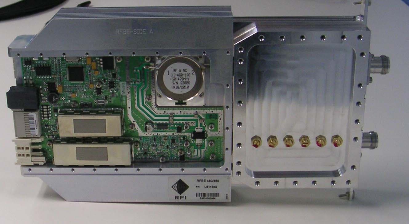
YK7085008701CXXXM
Aug 23, 2010RFBE Module
Equipment Class
TNB - Licensed Non-Broadcast Station Transmitter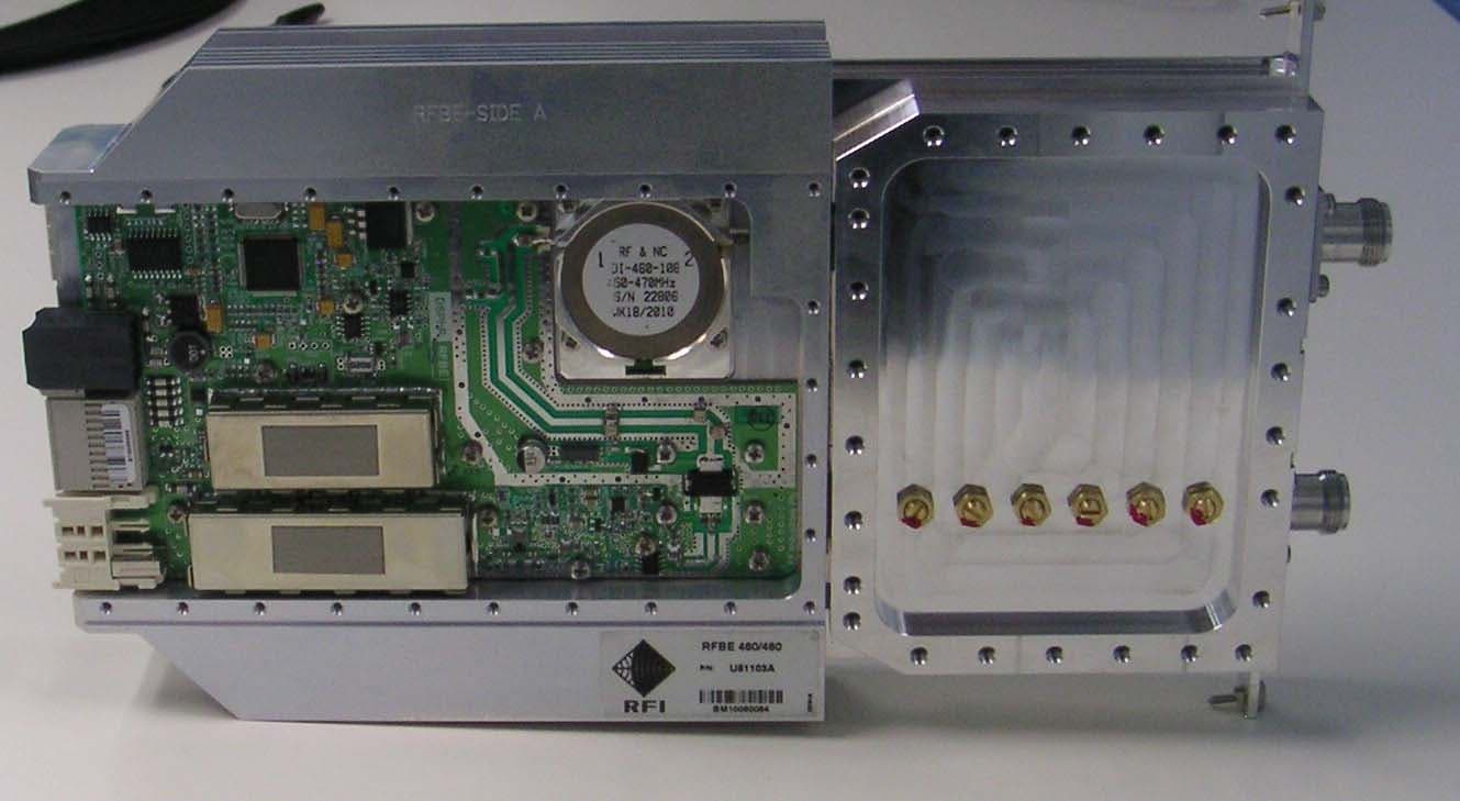
YK7045004701CXXXM
Aug 23, 2010RFBE Module
Equipment Class
TNB - Licensed Non-Broadcast Station Transmitter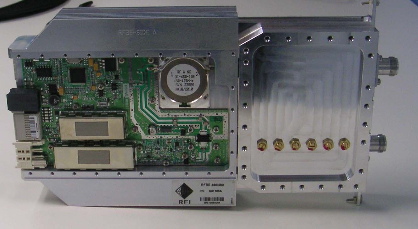
YK7040304201CXXXM
Aug 15, 2010RFBE Module
Equipment Class
TNB - Licensed Non-Broadcast Station Transmitter