YKLIRMFL02AMarubot Football League
IR Robot Co., Ltd.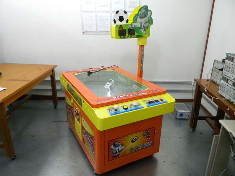
Click to zoom
Application Details
- Equipment Class
- DTS - Digital Transmission System
- Date of Grant
- Jul 25, 2010
- Application Purpose
- Original Equipment
- Date of Application
- Jul 23, 2010
- Equipment Note
- Marubot Football League
- Frequency Range
- 2405.00000000 - 2480.00000000
- Company
- IR Robot Co., Ltd.
- Country
- South Korea
Documents & Files
Document Text
Text extracted from the exhibit documents filed with the FCC. Open a document above to read the original.
Users Manual
www.irrobot.com MarubotFootballLeague (2 players) Instruction Manual (Score Bar Version) Important Please read the manual carefully before using this machine. Keep this manual for your reference at anytime. Specifications including design and color are subjected to change without notice. www.irrobot.com Table of Contents Table of Contents 5. Cleaning 32 6. Trouble Shooting 6.1 Power out . 33 6.2 The Robot is not moving . 34 6.3 The ball does not come out. 35 7. New Robot Replacement 36 8. Parts Replacement 8.1 Robot 39 8.1.1 Power Supplying Pins39 8.1.2 Tires 40 8.1.3 Magnetic Ball Holder 41 8.2 Machine 42 8.2.1 Lights 42 8.2.2 LEDs43 8.2.3 Control Parts (Joystick, Turbo Button, Steering, and Start Button) 43 9. Parts List 9.1 Machine 44 9.2 Robot 46 9.3 Block Diagram 47 10. Customer Service 48 Precautions for use2 1. Introduction 1.1 Product Information7 1.2 Components 8 1.3 Product Specifications 9 1.3.1 Machine 9 1.3.2 Robot14 2. Installation Instructions 2.1 General Instructions17 2.2 Installations 17 2.3 Handling the robot 22 2.4 How to set the robot speed 23 3. How to play? 24 4. Game Setting 4.1 Control Panel26 4.2 Sound Volume 26 4.3 Service Coin 26 4.4 Blow button 26 4.5 Mode, set, and enter button 27 4.5.1 Coin Setting28 4.5.2 Time Setting28 4.5.3 Credit Reset28 4.5.4 Attracting Sound Time Setting29 4.5.5 Ticket Dispenser Setting30 4.6 Coin Selector 31 www.irrobot.com WARNING Indicates a situation where disregarding the suggestions could result in death or serious injury. PRECAUTIONS FOR USE The following safety precautions are given throughout this manual. They must be strictly followed to protect those who install, use or maintain this product as well as to prevent other people’s injuries and property damages. People's injuries and property damages. • The following suggestions show the degree of danger and damage caused CAUTION Indicates a situation where disregarding the suggestions could result in injury or product damage. • The following graphic suggestions describe the types of precautions to be followed. Indicates a matter of which care should be taken. Indicates a matter which is forbidden. Indicates a matter which should be performed without fail. • The following graphic suggestions describe the types of precautions to be followed. In this instruction manual, some procedures require a qualified in-shop maintenance person or industry specialist. For such instructions, a qualified person must take care of the jobs. • Otherwise an electric shock, machine trouble, or a serious accident may result. • Replacing the machine parts, inspecting and maintaining the machines, and troubleshooting must be assigned only to a qualified in-shop maintenance person or industry specialist. This booklet gives instructions that hazardous jobs in particular must be handled by an industry specialist. Qualified in-shop maintenance person and industry specialist are defined as follows. Qualified in-shop maintenance person • A qualified in-shop maintenance person must have experience in maintaining amusement machines. Under the supervision of an amusement machines shop owner or manager, he or she routinely assembles, installs, inspects and maintains the amusement machines, or replaces their component units and consumable parts, in the amusement machines workshop and/or location. Jobs handled by qualified in-shop maintenance person • Assembling, installing, inspecting and maintaining amusement machines and replacing their component units and consumable parts. Industry specialist • An industry specialist must be engaged in designing, manufacturing, inspecting and servicing amusement machines. Or he or she must have an education in electrical, electronic and mechanical engineering, and routinely maintain and repair amusement machines. Jobs handled by industry specialist • Assembling and installing amusement machines and repairing and adjusting their electrical, electronic and mechanical component parts. Be sure to read the following www.irrobot.com Setting Up Be sure to consult your nearest dealer when setting up, moving or transporting this product. • This product should not be set up, moved or transported by any one other than an industry specialist. Doing so could result in injury or product damage. • When installing this product, set the 4 leg levelers evenly on the floor and make sure that the product is installed stably in a horizontal position. Unstable installation may result in injury or accident. • When installing this product, use caution not to apply undue force to opening and closing parts and other movable parts. Otherwise, injury and accident may result, or the product may be damaged. This product is an indoor game machine. Never set the game machine up outside. • Setting this product up outside could result in accidents or equipment damages. Do not set the game machine up near emergency exits. • Doing so could block exits in time of emergency and could result in death or serious injury. Do not set the game machine up. 1. In a place exposed to rain or moisture. 2. In a place exposed to direct sunlight. 3. In a place exposed to direct heat from air-conditioning and heating equipment, etc.. 4. Near hazardous flammable substance such as thinner and kerosene . • Otherwise an accident or malfunction may result. Do not place containers holding chemicals or water on or near the game machine. • Electrical shock or damage could be caused by water or foreign matter entering the inside of the machine. Do not place objects near the ventilating holes. • Doing so could cause the internal temperature to rise excessively, resulting in fire or equipment failure. Do not bend the power cord by force or place heavy objects on it. • Doing so could result in electrical shock or fire. Never plug or unplug the power cord with wet hands . • Doing so could result in electrical shock or fire. Never unplug the game machine by pulling the power cord. • Doing so could damage the cord, resulting in electrical shoc…
Text truncated - open the document above for the full version.
Cover Letter(s)
If you have not received all pages, please call the direct phone number. FAX : 031-428-5859 TEL : 031-428-5744 Federal Communications Commission 7435 Oakland Mills Road Columbia, MD 21046 Gentlemen: This letter is to comply with Section 0.457(d)(2)(i) and 0.459 pertaining to confidential material. We, IR Robot Co., Ltd.., would like the following documents regarding this submission for FCC ID: YKLIRMFL02A to be kept confidential. 1. Schematics 2. Parts List 3. Operational Description 4. Block diagram The above material contains trade secrets or technical data, which would customarily be guarded from competitors. We do not want these documents to be accessible to the general public. Sincerely, Jae Hyuk, Kyung / Manager
Cover Letter(s)
Chris Harvey From: Loh, Grace (Gunpo) [[email protected]] Sent: Friday, July 23, 2010 3:52 AM To: [email protected]; [email protected] Cc: [email protected]; Jeong, Feel (Gunpo) Subject: RE: IR Robot Co., Ltd., FCC ID: YKLIRMFL02A, Assessment NO.: AN10T0641, Notice#1 Attachments: apply-2.zip Page 1 of 3 7/23/2010 Dear Chris, Pls find attach to the revised documents. Thanks and regards, Grace Grace Loh/ 노 윤 정 Wireless Division Section Chief/ 과장 SGS Testing Korea Co., Ltd. 18-34, Sanbon-dong, Gunpo-si, Gyeonggi-do, Korea 435-040 Phone: +82 (0)31 428 5744 Mobile: +82 (0)10 2251 3461 Fax: +82 31 428 5859 E-mail : [email protected] citawireless_logo.gif -----Original Message----- From: [email protected] [mailto:[email protected]] Sent: Thursday, July 22, 2010 11:57 PM To: Jeong, Feel (Gunpo); Loh, Grace (Gunpo) Cc: [email protected]; [email protected] Subject: IR Robot Co., Ltd., FCC ID: YKLIRMFL02A, Assessment NO.: AN10T0641, Notice#1 Dear Feel Jeong and Grace Loh, You are listed as the Technical Contact for the above referenced TCB application. The following items need to be resolved before the review can be continued: 1. The Transmitter circuitry does not seem to be included in the schematics, which according to the Internal Photos and the Block Diagram are a module located on the User Board. Please provide the RF Schematics for the Transmitter Module (MG2455 ZIGBEE MODULE). Please provide the Schematics of the Transmitter RF Board. -> Attach to the RF Schematics of the module. 2. Labeling and Manual Information: The FCC ID Label exhibit shows the label location at on game controller, which seems to be a strange location (typically the labels are located near the name-plate, power inlet. Please confirm the Label Location for this device. Additionally, FCC 15.19 requires devices to be labeled with the FCC Compliance Statement unless the device is too small. This large device should be labeled with the FCC Compliance Statement of FCC 15.19. Additionally, since this device is also a Digital Device, the FCC Manual statements of FCC 15.105 should also be located in the manual. -> Updated FCC ID Label and user manual 3. You have requested the Parts List and Block Diagram to be held confidential, but these exhibits are also contained in the Users Manual which can not be held confidential. Please provide a Users Manual exhibit that does not contain the confidential information. -> Updated user manual 4. Please provide the Antenna Specification exhibit. -> Attach to the antenna spec The items indicated above must be submitted before processing can continue on the above referenced application. Failure to provide the requested information within 30 days of the original e-mail date may result in application dismissal and forfeiture of the filing fee. Also, please note that partial responses increase processing time and should not be submitted. Any questions about the content of this correspondence should be directed to the e-mail address listed below the name of the sender. Best regards, Chris Harvey [email protected] Information in this email and any attachments is confidential and intended solely for the use of the individual(s) to whom it is addressed or otherwise directed. Please note that any views or opinions presented in this email are solely those of the author and do not Page 2 of 3 7/23/2010 necessarily represent those of the Company. Finally, the recipient should check this email and an y attachments for the presence of viruses. The Company accepts no liability for any damage caused by any virus transmitted by this email. All SGS services are rendered in accordance with the applicable SGS conditions of service available on request and accessible at http://www.sgs.com/terms_and_conditions.htm Page 3 of 3 7/23/2010
External Photos
External photos of EUT Front view of EUT Rear view of EUT
ID Label/Location Info
FCC ID Label 1. FCC ID label drawing IR Robot Co., Ltd. Model : IRMFL-02A FCC ID : YKLIRMFL02A 2. FCC ID label location
Internal Photos
Internal photos of EUT Inter view of EUT Top view of Main PCB Bottom view of Main PCB Top view of RF module PCB Bottom view of RF module PCB Top view of Audio module Bottom view of Audio module Top view of Coin module Bottom view of Coin module Top view of Connector board Bottom view of Connector board Top view of Control board Bottom view of Control board Top view of Display module 1 Bottom view of Display module 1 Top view of Display module 2 Bottom view of Display module 2 Top view of Display module 3 Bottom view of Display module 3 Top view of Score control board Bottom view of Score control board Power Supply Power Supply Label Top view of Power supply board Bottom view of Power supply board The Fan Noise Filter
RF Exposure Info
Reprot Number: F690501/RF-RTL003989 Page: 34 of 35 The results shown in this test report refer only to the sample(s) tested unless otherwise stated. This test report cannot be reproduced, except in full, without prior written permission of the Company. SGS Testing Korea Co., Ltd. 8-34, Sanbon-dong, Gunpo-si, Gyeonggi-do, Korea, 435-040 Tel. +82 31 428 5700 / Fax. +82 31 427 2371 www.electrolab.kr.sgs.com 8. RF Exposure Evaluation 8.1 Environmental evaluation and exposure limit according to FCC CFR 47 part 1, 1.1307(b), 1.1310 According to FCC 1.1310 : The criteria listed in the following table shall be used to evaluate the environment impact of human exposure to radio frequency (RF) radiation as specified in §1.1307(b) LIMITS FOR MAXIMUM PERMISSIBLE EXPOSURE (MPE) 8.1.1. Friis transmission formula: Pd = (Pout*G)/(4*pi*R 2 ) Where Pd = power density in ㎽/㎠ Pout = output power to antenna in ㎽ G = gain of antenna in linear scale Pi = 3.1416 R = distance between observation point and center of the radiator in ㎝ Pd the limit of MPE, 1 ㎽/㎠. If we know the maximum gain of the antenna and the total power input to the antenna, through the calculation, we will know the distance where the MPE limit is reached. Frequency Range (㎒) Electric Field Strength(V/m) Magnetic Field Strength (A/m) Power Density (㎽/㎠) Average Time (A) Limits for Occupational /Control Exposures 300 – 1 500 -- -- F/300 6 1 500 – 100 000 -- -- 5 6 (B) Limits for General Population/Uncontrol Exposures 300 – 1 500 -- -- F/1500 6 1 500 – 100 000 -- -- 1 30 Reprot Number: F690501/RF-RTL003989 Page: 35 of 35 The results shown in this test report refer only to the sample(s) tested unless otherwise stated. This test report cannot be reproduced, except in full, without prior written permission of the Company. SGS Testing Korea Co., Ltd. 8-34, Sanbon-dong, Gunpo-si, Gyeonggi-do, Korea, 435-040 Tel. +82 31 428 5700 / Fax. +82 31 427 2371 www.electrolab.kr.sgs.com 8.1.2. Test Result of RF Exposure Evaluation Test Item : RF Exposure Evaluation Data Test Mode : Normal Operation 8.1.3. Output Power into Antenna & RF Exposure Evaluation Distance Channel Channel Frequency (㎒) Output Average Power to Antenna (㏈m) Antenna Gain (㏈i) Power Density at 20㎝ (㎽/㎠) LIMITS (㎽/㎠) Low 2 405 -8.58 0 0.000 03 1 Middle 2 445 -8.21 0 0.000 03 1 High 2 480 -8.62 0 0.000 03 1 Note : 1. The power density Pd (5th column) at a distance of 20㎝ calculated from the friis transmission formula is far below the limit of 1 ㎽/㎠ .
Test Report
Reprot Number: F690501/RF-RTL003989 Page: 2 of 35 The results shown in this test report refer only to the sample(s) tested unless otherwise stated. This test report cannot be reproduced, except in full, without prior written permission of the Company. SGS Testing Korea Co., Ltd. 8-34, Sanbon-dong, Gunpo-si, Gyeonggi-do, Korea, 435-040 Tel. +82 31 428 5700 / Fax. +82 31 427 2371 www.electrolab.kr.sgs.com INDEX Table of contents 1. General information --------------------------------------------------------------------------------------3 2. Transmitter radiated spurious emissions and conducted spurious emission --------------7 3. 6 ㏈ bandwidth ------------------------------------------------------------------------------------------- 16 4. Maximum peak output power --------------------------------------------------------------------------20 5. Power Spectral Density --------------------------------------------------------------------------------- 24 6. Transmitter AC Power Line Conducted Emission-------------------------------------------------28 7. Antenna Requirement ----------------------------------------------------------------------------------- 33 8. RF Exposure evaluation ----------------------------------------------------------------------- 34 Reprot Number: F690501/RF-RTL003989 Page: 3 of 35 The results shown in this test report refer only to the sample(s) tested unless otherwise stated. This test report cannot be reproduced, except in full, without prior written permission of the Company. SGS Testing Korea Co., Ltd. 8-34, Sanbon-dong, Gunpo-si, Gyeonggi-do, Korea, 435-040 Tel. +82 31 428 5700 / Fax. +82 31 427 2371 www.electrolab.kr.sgs.com 1. General Information 1.1. Testing Laboratory SGS Testing Korea Co., Ltd. - Wireless Div. 2FL, 18-34, Sanbon-dong, Gunpo-si, Gyeonggi-dong, Korea - 705, Dongcheon-dong Suji-gu, Yongin-si, Gyeonggi-do, Korea www.electrolab.kr.sgs.com Telephone : +82 +31 428 5700 FAX : +82 +31 427 2371 1.2. Details of Applicant Applicant : IR Robot Co., Ltd. Address : 401-1302-2 Bucheon Techno-Park 193 Yakdae-dong, Wonmi-gu, Bucheon-si, Gyonggi-do, Korea Contact Person : Sim, Jeong Seob Phone No. : +82 +32 326 3466 Fax No. : +82 +32 326 3468 1.3. Description of EUT Kind of Product Marubot Football League Model Name IRMFL-02A Serial Number N/A Frequency Range 2 405 ㎒ ~ 2 480 ㎒ Modulation Technique DSSS Number of Channels 16 Antenna Type Integral Type (Chip Antenna) Antenna Gain 0 ㏈i 1.4. Declaration by the manufacturer - The EUT has 2 modules Except the co-location transmitting mode. - All modules of hardware and software are same. So, we choose and test a module for representative at conducted test items, not radiated. Reprot Number: F690501/RF-RTL003989 Page: 4 of 35 The results shown in this test report refer only to the sample(s) tested unless otherwise stated. This test report cannot be reproduced, except in full, without prior written permission of the Company. SGS Testing Korea Co., Ltd. 8-34, Sanbon-dong, Gunpo-si, Gyeonggi-do, Korea, 435-040 Tel. +82 31 428 5700 / Fax. +82 31 427 2371 www.electrolab.kr.sgs.com 1.5. Test Equipment List EQUIPMENT MANUFACTURER MODEL CAL DUE. Signal Generator R & S SMR40 Sep. 25, 2010 Spectrum Analyzer R & S FSV30 Mar. 31, 2011 Attenuator Agilent 8494B Apr. 02, 2011 Preamplifier H.P 8447F Jul. 05, 2011 Preamplifier Agilent 8449B Mar. 31, 2011 High Pass Filter Wainwright WHK3.0/18G-10SS Sep. 29, 2010 Test Receiver R & S ESU26 Apr. 08, 2011 Bilog Antenna SCHWARZBECK MESSELEKTRONIK VULB9163 Jul. 22, 2010 Horn Antenna R & S HF 906 Oct. 08, 2011 Horn Antenna Schwarzbeck Mess-Elektronik BBHA9170 Jun. 29, 2012 Anechoic Chamber SY Corporation L × W × H (9.6 m×6.4 m×6.6 m) Jan. 27, 2011 Two-Line V-Network R & S ENV216 Jan. 06, 2011 Test Receiver R & S ESHS10 Jul. 13, 2011 Anechoic Chamber SY Corporation L × W × H (6.5 m×3.5 m×3.5 m) N.C.R Reprot Number: F690501/RF-RTL003989 Page: 5 of 35 The results shown in this test report refer only to the sample(s) tested unless otherwise stated. This test report cannot be reproduced, except in full, without prior written permission of the Company. SGS Testing Korea Co., Ltd. 8-34, Sanbon-dong, Gunpo-si, Gyeonggi-do, Korea, 435-040 Tel. +82 31 428 5700 / Fax. +82 31 427 2371 www.electrolab.kr.sgs.com 1.6. Summary of Test Results The EUT has been tested according to the following specifications: APPLIED STANDARD:FCC Part15 subpart C Standard section Test Item Result 15.205(a) 15.209 15.247(d) Transmitter Radiated Spurious Emissions Conducted Spurious Emission Complied 15.247(a)(2) 6 ㏈ Bandwidth Complied 15.247(b)(3) Maximum Peak Output Power Complied 15.247(e) Power Spectral Density Complied 15.207 Transmitter AC Power Line Conducted Emission Complied 15.247(i) 1.1307(b)(1) RF exposure evaluation Complied Reprot Number: F690501/RF-RTL003989 Page: 6 of 35 The results shown in this test report refer only to the sample(s) tested unless otherwise stated. This test report cannot be reproduced, except in full, without prior written permission of the Company. SGS Testing Korea Co., Ltd. 8-34, Sanbon-dong, Gunpo-si, Gyeonggi-do, Korea, 435-040 Tel. +82 31 428 5700 / Fax. +82 31 427 2371 www.electrolab.kr.sgs.com 1.7. Conclusion of worst-case The field strength of spurious emission was measured when all modules were made to the transmission status only for investigating. 1.8 Test report revision Revision Report number Description 0 F690501/RF-RTL003989 Initial Reprot Number: F690501/RF-RTL003989 Page: 7 of 35 The results shown in this test report refer only to the sample(s) tested unless otherwise stated. This test report cannot be reproduced, except in full, without prior written permission of the Company. SGS Testing Korea Co., Ltd. 8-34, Sanbon-dong, Gunpo-si, Gyeonggi-do, Korea, 435-040 Tel. +82 31 428 5700 / Fax. +82 31 427 2371 www.electrolab.kr.sgs.com 2. Transmitter Radiated Spurious Emissions and Conducted Spurious Emission 2.1. Test Setup 2.1.1. Transmitter Radiated Spurious Emissions The diag…
Text truncated - open the document above for the full version.
Test Setup Photos
Test setup photos of EUT A. Photo of Field Strength & Spurious Emission Test B. Photos of conducted power line test
Contact Information
Applicant
Jae Hyuk Kyung(manager)
Test Firm
SGS Korea Co., Ltd.Elan Lee
Technical Specifications
| # | Rule Parts | Frequency Range | Power Output |
|---|---|---|---|
| 1 | 15C | 2.40 GHz - 2.48 GHz | 1.64 mW |
Other Applications from IR Robot Co., Ltd.
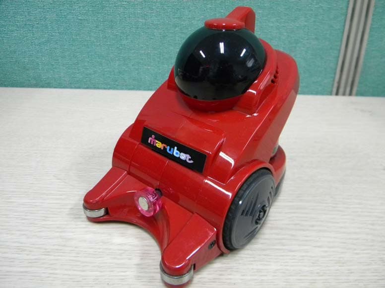
YKLIRMP0200001
Jul 25, 2010Marubot
Equipment Class
DTS - Digital Transmission System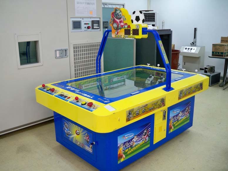
YKLIRMFL04A
Jul 25, 2010Marubot Football League
Equipment Class
DTS - Digital Transmission System