YKLIRMP0200001Marubot
IR Robot Co., Ltd.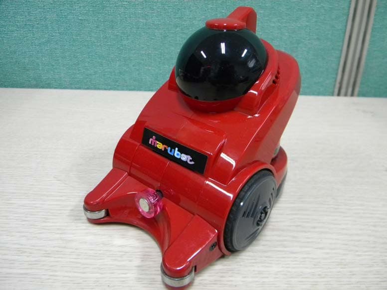
Click to zoom
Application Details
- Equipment Class
- DTS - Digital Transmission System
- Date of Grant
- Jul 25, 2010
- Application Purpose
- Original Equipment
- Date of Application
- Jul 23, 2010
- Equipment Note
- Marubot
- Frequency Range
- 2405.00000000 - 2480.00000000
- Company
- IR Robot Co., Ltd.
- Country
- South Korea
Documents & Files
Document Text
Text extracted from the exhibit documents filed with the FCC. Open a document above to read the original.
Users Manual
www.irrobot.com Service Manual Marubot FootballLeague IMPORTANT Please read the manual carefully and keep it in mind before repair the robot. Put this manual within touch of your reference in anytime. < ROBOT > www.irrobot.com < CONTENTS > < CONTENTS > 1. PLASTIC PARTS2 2-1) PLASTIC COMPOSITION 2. CIRCUIT PARTS4 3-1) MAIN BOARD 3-2) MAIN BOARD CABLE 3-3) POWER BOARD 3-4) BATTERY 3-5) MOTOR 3. ACCESSORY PARTS11 4-1) ACCESSORY COMPOSITION 4. STICKER PARTS13 5. BLOCK DIAGRAM14 6. REPLACEMENT15 7. TROUBLE SHOOTING19 8-1) POWER OUT 8-2) TURN DEFECT 8-3) MOVING DEFECT 8. PART LIST22 www.irrobot.com 1. PLASTIC PARTS 2 1 4 5 6 8 7 9 3 12 Colors (RED / WHITE) MOTOR CAP 6 12 Colors (RED / WHITE) BUMPER—BOTTOM 5 12 Colors (RED / WHITE) BUMPER-TOP 4 1 BASE 3 1 HEAD 7 12 Colors (RED / WHITE) BODY-RIGHT 2 12 Colors (RED / WHITE) BODY-LEFT 1 NoPARTS DESCRIPTIONQ’Ty 8 FACE FACE WINDOW1 9 WHEEL Front Tire Wheel2 www.irrobot.com 1. Body-Left2. Body-Right 3. BASE 4. BUMPER-TOP 5. BUMPER-BOTTOM 6. MOTOR CAP 7. HEAD 8. FACE 9. WHEEL9. WHEEL 1-1) PLASTIC COMPOSITION www.irrobot.com 1Power supply Board POWER BOARD 2 2NIDEC (BL-DC Motor W/Gear) MOTOR 4 1Lithium Polymer (7.4V 1000mAH) BATTERY 3 1Robot Controller + Face Expression MAIN BOARD 1 NoPARTSDESCRIPTIONQ’Ty 1 2 3 4 2. CIRCUIT PARTS www.irrobot.com 2-1) MAIN BOARD < TOP > < BOTTOM > Battery (Charge/Discharge)BATT15 Motor Control (Right)MOTOR R14 Download port (to Power Board)ISP6 Zigbee ModuleJ22 Zigbee ModuleJ11 RemarkDescriptionReference NoNo DC Power In (to Power Board)PCON17 Motor Control (Left)MOTOR L13 3 5 4 6 7 1 2 •Assembly (Zigbee Module) INSERT www.irrobot.com 2-2) MAIN BOARD CABLE 2-2-1) MOTOR CABLE 2-2-2) ISP CABLE 115mm MOTOR CON MAIN BOARD MOTOR L1 or MOTOR R1 Molex : 5264-05 1 : ORANGE (DIR) 2 : WHITE (PWM) 3 : YELLOW(ENABLE) 4 : RED(12V) 5 : BLACK (GND) 3 4 2 1 5 5 1 2 3 4 1 : ORANGE (DIR) 2 : WHITE (PWM) 3 : YELLOW(ENABLE) 4 : RED(12V) 5 : BLACK (GND) < MOTOR > CON AWG28 55mm MAIN BOARD ( ISP )POWER BOARD ( J3 ) YEON-HO: YDH 200-06 YEON-HO: YDH 200-06 AWG26 1 : RED (MISO) 2 : BLACK (MOSI) 3 : BLACK (SCK) 4 : BLACK (RST_CTL) 5 : BLACK (RST_FACE) 6 : BLACK (TP) 1 : RED (MISO) 2 : BLACK (MOSI) 3 : BLACK (SCK) 4 : BLACK (RST_CTL) 5 : BLACK (RST_FACE) 6 : BLACK (TP) www.irrobot.com 2-2-3) POWER CABLE 55mm MAIN BOARD (PCON)POWER BOARD (PCON) YEON-HO: YDH 200-10 YEON-HO: YDH 200-10 AWG26 1 : RED ( PB 12V) 2 : BLACK (PB 12V) 3,4: BLACK (PB GND) 5 : BLACK (5V) 6 : BLACK (VR) 7 : BLACK (DIP S/W 0) 8 : BLACK (DIP S/W 1) 9: BLACK (DIP S/W 2) 10 : BLACK (DIP S/W 3) 11,12 : BLACK (GND) 1 : RED ( PB 12V) 2 : BLACK (PB 12V) 3,4: BLACK (PB GND) 5 : BLACK (5V) 6 : BLACK (VR) 7 : BLACK (DIP S/W 0) 8 : BLACK (DIP S/W 1) 9: BLACK (DIP S/W 2) 10 : BLACK (DIP S/W 3) 11,12 : BLACK (GND) www.irrobot.com 2-3) POWER BOARD Download portJ32 DC Power OutPCON1 RemarkDescriptionReference NoNo Robot Program Download Port DATA3 < BOTTOM > < TOP > 1 2 3 www.irrobot.com 2-4) BATTERY (1)44(W)x35(L)x14.5(T)BATTERY2 Molex 5264-02HOUSING1 RemarkDescriptionPartsNo 2P , 60mm (AWG 26)WIRE3 1 2 3 •Note 1) Battery Specification - Lithium Polymer Battery ( 2 Cell ) - Capacity : 1,050mAh (Typ) - Voltage : 7.4V (Normal) - Charge Voltage : 8.4V www.irrobot.com 2-5) MOTOR •Note 1) Motor Specification - BL-DC Motor ( NIDEC 13H570 ) - Operating Voltage : 12V (Normal) - Operating Current : 0.5A (Max) - Run Torque : 6.2mN m (Max) (1)35(W)x25(L)x25(T)MOTOR2 IG 22 (1/4)GEAR1 RemarkDescriptionPartsNo Motor Control ( Connect the Main Board )CON3 1 2 3 www.irrobot.com 1SPONGE8 1BH M3x4 TappingSCREW #19 1Ball guideMAGNETIC HOLDER7 2625 ZZ (5,16,5)BEARING6 25IRON BALL5 6PSP-280G-080 (2.5g)POWER SUPPLY PIN4 1 SetAcetal + PinREAR TIRE SET3 2SNAP RING2 2RubberFRONT TIRE1 8BH M2x6 MachineSCREW #513 2FH M2.6x15 TappingSCREW #412 2FH M3x8 TappingSCREW #311 14PH M3x6 TapppingSCREW #210 NoPARTS DESCRIPTIONQ’Ty 1 2 3 4 12 6 11 7 13 9 10 5 8 3. ACCESSORY PARTS www.irrobot.com 3-1) ACCESSORY COMPOSITION 1. Front Tire2. Snap Ring3. Rear Tire Set PinAcetal Tire 4. Power Supply Pin5. Iron ball6. Bearing7. Magnetic Holder 9. BH M3x4 Tapping < Screws > 10. PH M3x6 Tapping 11. FH M3x8 Tapping 12. FH M2.6x15 Tapping 13. BH M2x6 Machine 8. Sponge www.irrobot.com 1TEAM STICKER3 1 SetSIDE STICKER2 1FRONT STICKER1 NoPARTS DESCRIPTIONQ’Ty 1 2 3 4. STICKER PARTS www.irrobot.com 6. REPLACEMENT 2) Pull out the front wheel. *Turn off the Robot power switch before replacement parts. 1) Disentangle the snap ring with a snap ring pliers or a pincette. < A snap ring pliers >< Snap Ring > < A pincette > 3) Releasing 5 screws on the robot bottom. Front Wheel and Tire Replacement www.irrobot.com 4) Releasing 2 screws on the bumper side. 5) Separate the Bumper Set. Lift up the magnetic holder and pull it out to the front. Bumper Set, Magnetic Holder Replacement 6) Lift up the front of Body case. 7) Hold the Body cover and Bottom case in hand. Pull the Body cover out of the Bottom case. < Separation of Body cover > www.irrobot.com 8) Unplug the Motor(Left, Right) cable and Battery Cable. Remove the Battery. MOTOR LEFT CABLE MOTOR RIGHT CABLE BATTERY CABLE Battery Replacement 9) Release 3 screws on the Main board. 10) Lift up Main Board. Unplug the ISP Cable and Power Cable on the Main Board. < Separation of Main Board > POWER CABLE ISP CABLE Main Board Replacement www.irrobot.com 11) Unplug the ISP Cable and Power Cable on the Power Board. Releasing 3 screws on the Power Board. < Separation of Main Board > Power Board Replacement 12) Use small (+) Driver releasing 8 screws on the Motor cap. Check the Power supply pins before replacement Power Board. 13) Use small (-) Driver lift up the Motor Cap. Uncover the Motor cap. < Separation of Motor Cap > Motor, Motor Cable Replacement www.irrobot.com 7-1) POWER OUT Robot is not working. (Face LED OFF) Check the Power Supply Pins. ( Battery, Power Board ) 7. TROUBLE SHOOTING RO BO T Po w e r O u t Ro b o t Po w e r S/ W O N ? Turn on the Switch No Yes Po w e r Su p p l y Pi n s condition OK? …
Text truncated - open the document above for the full version.
Cover Letter(s)
Date: July. 12, 2010 Federal Communications Commission 7435 Oakland Mills Road Columbia MD 21046 c.c. Compliance Certification Services Certification Division 47173 Benicia Street Fremont, CA 94538, USA To whom it may concern: I, the undersigned, hereby authorize Lab Manager Jim. Kim of SGS Testing Korea Co., Ltd and hereafter referred to as SGS Testing Korea, to act on our behalf in all manners relating to application for equipment authorization, including signing of all documents relating to these matters. Any and all acts carried out by Lab Manager Jim. Kim of SGS Testing Korea Co., Ltd on our behalf shall have the same effect as acts of our own. I, the undersigned, hereby certify that we are not subject to a denial of federal benefits, that includes FCC benefits, pursuant to Section 5301 of the Anti-Drug Abuse Act of 1988, 21 U.S.C. 853(a). In authorizing SGS Testing Korea as our agent, we still recognize that we are responsible to: a) comply with the relevant provisions of the certification program; b) make all necessary arrangements for the conduct of the evaluation, including provision for examining documentation and access to all areas, records (including internal audit reports) and personnel for the purposes of evaluation (e.g. testing, inspection, assessment, surveillance, reassessment) and resolution of complaints; c) make claims regarding certification only in respect of the scope for which certification has been granted; d) do not use our product certification in such a manner as to bring the Certification Division into disrepute and not make any statement regarding our product certification which the Certification Division may consider misleading or unauthorized; e) upon suspension or cancellation of certification, discontinue use of all advertising matter that contains any reference thereto and return any certification documents as required by the Certification Division; f) use certification only to indicate the products are certified as being in conformity with specified standards; g) endeavor to ensure that no certificate or report nor any part thereof is used in a misleading manner; h) ensure that any reference to our product certification in communication media such as documents, brochures or advertising, complies with the requirements of the Certification Division; i) keep a record of all complaints made known to the us relating to the product’s compliance with requirements of the relevant standard and to make these records available to the Certification Division when requested; j) take appropriate action with respect to such complaints and any deficiencies found in products or services that affect compliance with the requirements for certification; k) document the actions taken. This authorization is valid until further written notice from the applicant. Sincerely Yours, Jae Hyuk, Kyung / Manager REMARK: 1. This authorization letter will be sent along with your application when filing with the Certification Division. 2. Please follow the format and type it on company letterhead and send original to us. 3. Authorized signature must be in agreement with grantee code contact in FCC database.
Cover Letter(s)
If you have not received all pages, please call the direct phone number. FAX : 031-428-5859 TEL : 031-428-5744 Federal Communications Commission 7435 Oakland Mills Road Columbia, MD 21046 Gentlemen: This letter is to comply with Section 0.457(d)(2)(i) and 0.459 pertaining to confidential material. We, IR Robot Co., Ltd.., would like the following documents regarding this submission for FCC ID: YKLIRMP0200001 to be kept confidential. 1. Schematics 2. Parts List 3. Operational Description 4. Block diagram The above material contains trade secrets or technical data, which would customarily be guarded from competitors. We do not want these documents to be accessible to the general public. Sincerely, Jae Hyuk, Kyung / Manager
Cover Letter(s)
Chris Harvey From: Loh, Grace (Gunpo) [[email protected]] Sent: Friday, July 23, 2010 3:26 AM To: [email protected]; [email protected] Cc: [email protected]; Jeong, Feel (Gunpo) Subject: RE: IR Robot Co., Ltd., FCC ID: YKLIRMP0200001, Assessment NO.: AN10T0643, Notice#1 Attachments: apply-2.zip Page 1 of 3 7/23/2010 Dear Chris, Pls find attach to the revised documents. Pls refer to the rely as below. Thanks and regards, Grace Grace Loh/ 노 윤 정 Wireless Division Section Chief/ 과장 SGS Testing Korea Co., Ltd. 18-34, Sanbon-dong, Gunpo-si, Gyeonggi-do, Korea 435-040 Phone: +82 (0)31 428 5744 Mobile: +82 (0)10 2251 3461 Fax: +82 31 428 5859 E-mail : [email protected] citawireless_logo.gif -----Original Message----- From: [email protected] [mailto:[email protected]] Sent: Thursday, July 22, 2010 11:54 PM To: Jeong, Feel (Gunpo); Loh, Grace (Gunpo) Cc: [email protected]; [email protected] Subject: IR Robot Co., Ltd., FCC ID: YKLIRMP0200001, Assessment NO.: AN10T0643, Notice#1 Dear Feel Jeong and Grace Loh, You are listed as the Technical Contact for the above referenced TCB application. The following items need to be resolved before the review can be continued: 1. The Transmitter circuitry does not seem to be included in the schematics, which according to the Internal Photos and the Block Diagram are a module located on the User Board. Please provide the RF Schematics for the Transmitter Module (MG2455 ZIGBEE MODULE). Please provide the Schematics of the Transmitter RF Board. -> Attach to the schematics of RF Module 2. For the required Users Manual exhibit you have provided a Service Manual that seems to contain information that could be considered company confidential. The Users Manual exhibits can not be held as permanently confidential for FCC/TCB Certification filings. 3. You have requested the Parts List and Block Diagram to be held confidential, but these exhibits are also contained in the Users Manual (Service Manual) which can not be held confidential. Please provide a Users Manual exhibit that does not contain the confidential information. -> Attach to the revised user manual 4. Please provide the Antenna Specification exhibit for this transmitter. -> Attach to the antenna spec. 5. This robot device operates on a rechargeable battery which is charged from the Game Console onto which this robot is installed. If the transmitter will function while the battery is charging from the game console, then this would be considered indirect connection to the AC power, which must be tested for AC Conducted Emissions. Please provide AC Conducted emissions compliance information if needed. -> Transmitter is not function while the battery is charging. The items indicated above must be submitted before processing can continue on the above referenced application. Failure to provide the requested information within 30 days of the original e-mail date may result in application dismissal and forfeiture of the filing fee. Also, please note that partial responses increase processing time and should not be submitted. Any questions about the content of this correspondence should be directed to the e-mail address listed below the name of the sender. Best regards, Chris Harvey [email protected] Page 2 of 3 7/23/2010 Information in this email and any attachments is confidential and intended solely for the use of the individual(s) to whom it is addressed or otherwise directed. Please note that any views or opinions presented in this email are solely those of the author and do not necessarily represent those of the Company. Finally, the recipient should check this email and an y attachments for the presence of viruses. The Company accepts no liability for any damage caused by any virus transmitted by this email. All SGS services are rendered in accordance with the applicable SGS conditions of service available on request and accessible at http://www.sgs.com/terms_and_conditions.htm Page 3 of 3 7/23/2010
External Photos
External photos of EUT Front view of EUT Rear view of EUT
ID Label/Location Info
FCC ID Label 1. FCC ID label drawing IR Robot Co., Ltd. Model : IRMP 02 00001 FCC ID : YKLIRMP0200001 2. FCC ID label location
Internal Photos
Internal photos of EUT Inter view of EUT Top view of Main PCB Bottom view of Main PCB Top view of RF module PCB Bottom view of RF module PCB Top view of LED board Bottom view of LED board Top view of Power board Bottom view of Power board The Motor The Battery
RF Exposure Info
Report Number: F690501/RF-RTL003987 Page: 29 of 30 The results shown in this test report refer only to the sample(s) tested unless otherwise stated. This test report cannot be reproduced, except in full, without prior written permission of the Company. SGS Testing Korea Co., Ltd. 8-34, Sanbon-dong, Gunpo-si, Gyeonggi-do, Korea, 435-040 Tel. +82 31 428 5700 / Fax. +82 31 427 2371 www.electrolab.kr.sgs.com 7. RF Exposure Evaluation 7.1 Environmental evaluation and exposure limit according to FCC CFR 47 part 1, 1.1307(b), 1.1310 According to FCC 1.1310 : The criteria listed in the following table shall be used to evaluate the environment impact of human exposure to radio frequency (RF) radiation as specified in §1.1307(b) LIMITS FOR MAXIMUM PERMISSIBLE EXPOSURE (MPE) 7.1.1. Friis transmission formula: Pd = (Pout*G)/(4*pi*R 2 ) Where Pd = power density in ㎽/㎠ Pout = output power to antenna in ㎽ G = gain of antenna in linear scale Pi = 3.1416 R = distance between observation point and center of the radiator in ㎝ Pd the limit of MPE, 1 ㎽/㎠. If we know the maximum gain of the antenna and the total power input to the antenna, through the calculation, we will know the distance where the MPE limit is reached. Frequency Range (㎒) Electric Field Strength(V/m) Magnetic Field Strength (A/m) Power Density (㎽/㎠) Average Time (A) Limits for Occupational /Control Exposures 300 – 1 500 -- -- F/300 6 1 500 – 100 000 -- -- 5 6 (B) Limits for General Population/Uncontrol Exposures 300 – 1 500 -- -- F/1500 6 1 500 – 100 000 -- -- 1 30 Report Number: F690501/RF-RTL003987 Page: 30 of 30 The results shown in this test report refer only to the sample(s) tested unless otherwise stated. This test report cannot be reproduced, except in full, without prior written permission of the Company. SGS Testing Korea Co., Ltd. 8-34, Sanbon-dong, Gunpo-si, Gyeonggi-do, Korea, 435-040 Tel. +82 31 428 5700 / Fax. +82 31 427 2371 www.electrolab.kr.sgs.com 7.1.2. Test Result of RF Exposure Evaluation Test Item : RF Exposure Evaluation Data Test Mode : Normal Operation 7.1.3. Output Power into Antenna & RF Exposure Evaluation Distance Channel Channel Frequency (㎒) Output Average Power to Antenna (㏈m) Antenna Gain (㏈i) Power Density at 20㎝ (㎽/㎠) LIMITS (㎽/㎠) Low 2 405 -9.20 0 0.000 02 1 Middle 2 445 -9.05 0 0.000 02 1 High 2 480 -9.86 0 0.000 02 1 Note : 1. The power density Pd (5th column) at a distance of 20㎝ calculated from the friis transmission formula is far below the limit of 1 ㎽/㎠ .
Test Report
Report Number: F690501/RF-RTL003987 Page: 2 of 30 The results shown in this test report refer only to the sample(s) tested unless otherwise stated. This test report cannot be reproduced, except in full, without prior written permission of the Company. SGS Testing Korea Co., Ltd. 8-34, Sanbon-dong, Gunpo-si, Gyeonggi-do, Korea, 435-040 Tel. +82 31 428 5700 / Fax. +82 31 427 2371 www.electrolab.kr.sgs.com INDEX Table of contents 1. General information --------------------------------------------------------------------------------------3 2. Transmitter radiated spurious emissions and conducted spurious emission --------------7 3. 6 ㏈ bandwidth ------------------------------------------------------------------------------------------- 16 4. Maximum peak output power --------------------------------------------------------------------------20 5. Power Spectral Density --------------------------------------------------------------------------------- 24 6. Antenna Requirement ----------------------------------------------------------------------------------- 28 7. RF Exposure evaluation ----------------------------------------------------------------------- 29 Report Number: F690501/RF-RTL003987 Page: 3 of 30 The results shown in this test report refer only to the sample(s) tested unless otherwise stated. This test report cannot be reproduced, except in full, without prior written permission of the Company. SGS Testing Korea Co., Ltd. 8-34, Sanbon-dong, Gunpo-si, Gyeonggi-do, Korea, 435-040 Tel. +82 31 428 5700 / Fax. +82 31 427 2371 www.electrolab.kr.sgs.com 1. General Information 1.1. Testing Laboratory SGS Testing Korea Co., Ltd. - Wireless Div. 2FL, 18-34, Sanbon-dong, Gunpo-si, Gyeonggi-dong, Korea - 705, Dongcheon-dong Suji-gu, Yongin-si, Gyeonggi-do, Korea www.electrolab.kr.sgs.com Telephone : +82 +31 428 5700 FAX : +82 +31 427 2371 1.2. Details of Applicant Applicant : IR Robot Co., Ltd. Address : 401-1302-2 Bucheon Techno-Park 193 Yakdae-dong, Wonmi-gu, Bucheon-si, Gyonggi-do, Korea Contact Person : Sim, Jeong Seob Phone No. : +82 +32 326 3466 Fax No. : +82 +32 326 3468 1.3. Description of EUT Kind of Product Marubot Model Name IRMP 02 00001 (the addition of model name : IRMP 02 00002) Serial Number N/A Frequency Range 2 405 ㎒ ~ 2 480 ㎒ Modulation Technique DSSS Number of Channels 16 Antenna Type Integral Type (Chip Antenna) Antenna Gain 0 ㏈i 1.4. Declaration by the manufacturer - N/A. Report Number: F690501/RF-RTL003987 Page: 4 of 30 The results shown in this test report refer only to the sample(s) tested unless otherwise stated. This test report cannot be reproduced, except in full, without prior written permission of the Company. SGS Testing Korea Co., Ltd. 8-34, Sanbon-dong, Gunpo-si, Gyeonggi-do, Korea, 435-040 Tel. +82 31 428 5700 / Fax. +82 31 427 2371 www.electrolab.kr.sgs.com 1.5. Test Equipment List EQUIPMENT MANUFACTURER MODEL CAL DUE. Signal Generator R & S SMR40 Sep. 25, 2010 Spectrum Analyzer R & S FSV30 Mar. 31, 2011 Attenuator Agilent 8494B Apr. 02, 2011 Preamplifier H.P 8447F Jul. 05, 2011 Preamplifier Agilent 8449B Mar. 31, 2011 High Pass Filter Wainwright WHK3.0/18G-10SS Sep. 29, 2010 Test Receiver R & S ESU26 Apr. 08, 2011 Bilog Antenna SCHWARZBECK MESSELEKTRONIK VULB9163 Jul. 22, 2010 Horn Antenna R & S HF 906 Oct. 08, 2011 Horn Antenna Schwarzbeck Mess-Elektronik BBHA9170 Jun. 29, 2012 Anechoic Chamber SY Corporation L × W × H (9.6 m×6.4 m×6.6 m) Jan. 27, 2011 Report Number: F690501/RF-RTL003987 Page: 5 of 30 The results shown in this test report refer only to the sample(s) tested unless otherwise stated. This test report cannot be reproduced, except in full, without prior written permission of the Company. SGS Testing Korea Co., Ltd. 8-34, Sanbon-dong, Gunpo-si, Gyeonggi-do, Korea, 435-040 Tel. +82 31 428 5700 / Fax. +82 31 427 2371 www.electrolab.kr.sgs.com 1.6. Summary of Test Results The EUT has been tested according to the following specifications: APPLIED STANDARD:FCC Part15 subpart C Standard section Test Item Result 15.205(a) 15.209 15.247(d) Transmitter Radiated Spurious Emissions Conducted Spurious Emission Complied 15.247(a)(2) 6 ㏈ Bandwidth Complied 15.247(b)(3) Maximum Peak Output Power Complied 15.247(e) Power Spectral Density Complied 15.207 Transmitter AC Power Line Conducted Emission Complied 15.247(i) 1.1307(b)(1) RF exposure evaluation Complied Report Number: F690501/RF-RTL003987 Page: 6 of 30 The results shown in this test report refer only to the sample(s) tested unless otherwise stated. This test report cannot be reproduced, except in full, without prior written permission of the Company. SGS Testing Korea Co., Ltd. 8-34, Sanbon-dong, Gunpo-si, Gyeonggi-do, Korea, 435-040 Tel. +82 31 428 5700 / Fax. +82 31 427 2371 www.electrolab.kr.sgs.com 1.7. Information of added model name Model information IRMP 02 00001 Red Color (Basic) IRMP 02 00002 White Color 1.8 Test report revision Revision Report number Description 0 F690501/RF-RTL003987 Initial Report Number: F690501/RF-RTL003987 Page: 7 of 30 The results shown in this test report refer only to the sample(s) tested unless otherwise stated. This test report cannot be reproduced, except in full, without prior written permission of the Company. SGS Testing Korea Co., Ltd. 8-34, Sanbon-dong, Gunpo-si, Gyeonggi-do, Korea, 435-040 Tel. +82 31 428 5700 / Fax. +82 31 427 2371 www.electrolab.kr.sgs.com 2. Transmitter Radiated Spurious Emissions and Conducted Spurious Emission 2.1. Test Setup 2.1.1. Transmitter Radiated Spurious Emissions The diagram below shows the test setup that is utilized to make the measurements for emission from 30 ㎒ to 1 ㎓ Emissions. The diagram below shows the test setup that is utilized to make the measurements for emission from 1 ㎓ to 24 ㎓ Emissions. Report Number: F690501/RF-RTL003987 Page: 8 of 30 The results shown in this test report refer only to the sample(s) tested unless otherwise stated. This test report cannot be reproduced, except in full, without prior written permis…
Text truncated - open the document above for the full version.
Test Setup Photos
Test setup photos of EUT Photo of Field Strength & Spurious Emission Test
Contact Information
Applicant
Jae Hyuk Kyung(manager)
Test Firm
SGS Korea Co., Ltd.Elan Lee
Technical Specifications
| # | Rule Parts | Frequency Range | Power Output |
|---|---|---|---|
| 1 | 15C | 2.40 GHz - 2.48 GHz | 1.06 mW |
Other Applications from IR Robot Co., Ltd.
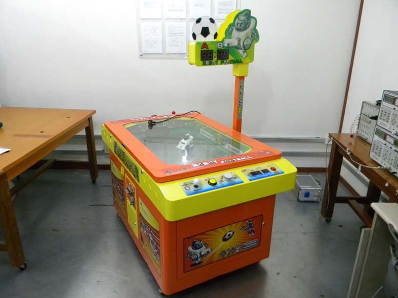
YKLIRMFL02A
Jul 25, 2010Marubot Football League
Equipment Class
DTS - Digital Transmission System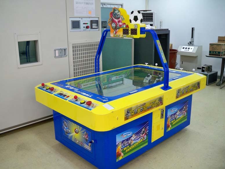
YKLIRMFL04A
Jul 25, 2010Marubot Football League
Equipment Class
DTS - Digital Transmission System