YMD-ECL2010DCM1Ecolab Hand Hygiene Monitoring System
Ecolab Inc.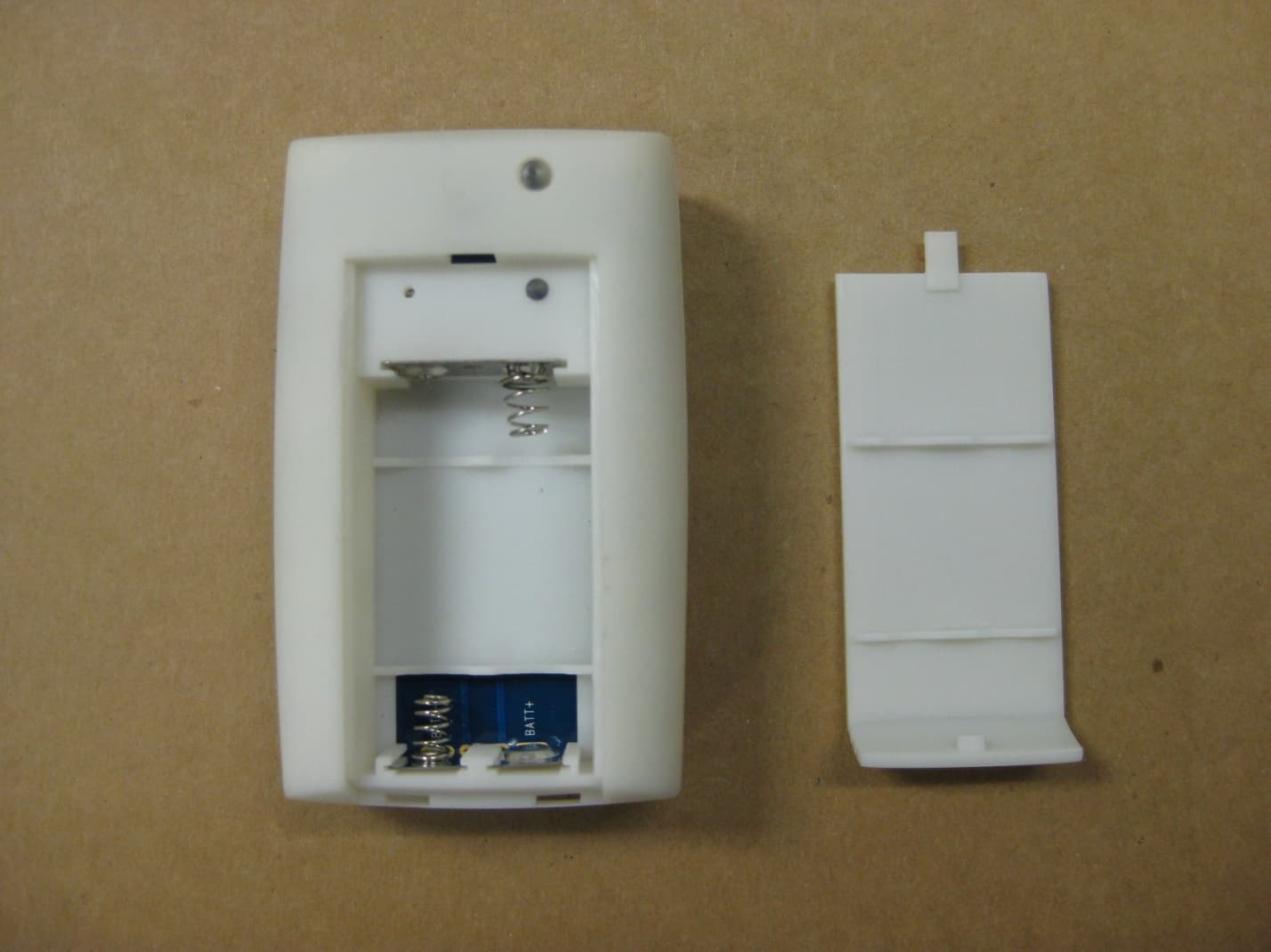
Click to zoom
Application Details
- Equipment Class
- DXX - Part 15 Low Power Communication Device Transmitter
- Date of Grant
- Nov 14, 2010
- Application Purpose
- Original Equipment
- Date of Application
- Nov 14, 2010
- Equipment Note
- Ecolab Hand Hygiene Monitoring System
- Frequency Range
- 0.13480000 - 0.13480000
- Company
- Ecolab Inc.
- Country
- United States
Documents & Files
Document Text
Text extracted from the exhibit documents filed with the FCC. Open a document above to read the original.
Users Manual
Ecolab Hand Hygiene Monitoring System User Manual Dispenser and Dispenser Communication Module Installation of Hand Hygiene Dispenser CAUTION: The bottom of the dispenser should be mounted about 10 inches (25cm) above horizontal surfaces. Shorter distances may be acceptable depending on the reflectivity of the surface over which the dispenser is being mounted. The LED indicator can be used to determine the minimum acceptable distance over a particular surface. This can be accomplished by installing batteries in the dispenser (reference step 4. Battery Installation), verifying the dispenser is working correctly, then bringing the bottom of the dispenser towards the surface and watching the dispenser LED change from a once per 0.5 second green flash, to an alternating green and red flash. (See step 5, Dispenser Status Indicator.) Do not install in showers or in direct contact with water. The dispenser can be installed either by using the tape that is supplied on the back of the dispenser, or by using screws and anchors. Before installation of the dispenser, make sure the cable which connects the dispenser to the communication module is routed under the chassis of the dispenser. Connect the communication cable to the pins on the sensor board inside the dispenser. 1. Installing unit with adhesive tape A. Clean and thoroughly dry the wall that the dispenser is to be mounted to. Alcohol wipes work well for hard surfaces such as ceramic tile. B. Remove the protective backing on the tape that is affixed to the back of the dispenser. Ensure proper location. Mount the unit at the desired location by pressing unit against mounting surface. C. Open the front cover and apply pressure to the back plate for at least 30 seconds to assure a good bond between the tape and the wall. 2. Installing unit with screws and anchors. The dispenser is designed to match many of the screw holes of Ecolab and some competitive dispensers. By positioning the dispenser appropriately on the wall, it may be possible to use the previous anchor locations. A. Use # 8 screws and appropriate anchors (use at least 4 screws to secure the dispenser to the wall, space them out as far as possible on the back plate of the dispenser). B. Keep the cover fully open. C. Place the unit against the wall at the desired location. i. Using the holes on the back of the dispenser as a template, mark the wall with a pencil or sharp object. ii. Using an appropriately sized drill bit for the anchors, drill the holes iii. Insert anchors into the holes. iv. Screw the dispenser onto the wall. v. Installation of Communication Module 1. Locate the Communication Module (CM) near the dispenser. 2. Route the unconnected end of the communication cable though the rectangular cutout in the chassis of the CM. 3. Using steps 1 or 2 in the Dispenser installation instruction above, attach CM to the wall. 4. Connect the free end of the communication cable to the CM PWA. 5. Snap the cover to the chassis of the CM 6. Insert two AA batteries into the CM and snap the battery door into place A hand hygiene event is communicated to the badge each time the dispenser is activated to dispense product. Communication with a badge can be verified by observing the activation of the green LED on the badge and dispenser when product is dispensed. NOTE: For communication between the badge and the dispenser to be initiated successfully, the badge must be within three (3) feet of the dispenser. FCC Compliance Statements (Data Collection Station, Dispenser Communication Module) Compliance Statement (Part 15.19) This device complies with Part 15 of the FCC Rules. Operation is subject to the following two conditions: 1. This device may not cause harmful interference, and 2. This device must accept any interference received, including interference that may cause undesired operation. Warning (Part 15.21) Changes or modifications not expressly approved by the party responsible for compliance could void the user’s authority to operate the equipment. FCC Interference Statement (Part 15.105 (b) This equipment has been tested and found to comply with the limits for a Class B digital device, pursuant to Part 15 of the FCC Rules. These limits are designed to provide reasonable protection against harmful interference in a residential installation. This equipment generates uses and can radiate radio frequency energy and, if not installed and used in accordance with the instructions, may cause harmful interference to radio communications. However, there is no guarantee that interference will not occur in a particular installation. If this equipment does cause harmful interference to radio or television reception, which can be determined by turning the equipment off and on, the user is encouraged to try to correct the interference by one of the following measures: - Reorient or relocate the receiving antenna. - Increase the separation between the equipment and receiver. - Connect the equipment into an outlet on a circuit different from that to which the receiver is connected. - Consult the dealer or an experienced radio/TV technician for help. RF Exposure (OET Bulletin 65) To comply with FCC/IC RF exposure requirements for mobile transmitting devices, this transmitter should only be used or installed at locations where there is at least 20cm separation distance between the antenna and all persons. To comply with FCC/IC RF exposure limits for general population / uncontrolled exposure, the antenna(s) used for this transmitter must be installed to provide a separation distance of at least 20 cm from all persons and must not be co-located or operating in conjunction with any other antenna or transmitter. Industry Canada Compliance Statement Section 7.1.5 of RSS‐GEN Operation is subject to the following two conditions: 1) this device may not cause interference, and 2) this device must accept any interference, including interference that may cause undesired operation of the device.
Cover Letter(s)
370 Wabasha Street N St. Paul, MN 55102 Request for Confidentiality Date: July 16, 2010 Subject: Confidentiality Request for FCC ID: YMD-ECL2010DCM1 Pursuant to FCC 47 CRF 0.457(d) and 0.459 and IC RSP-100, Section 10, the applicant requests that a part of the subject FCC application be held confidential. Type of Confidentiality Requested Exhibit Short Term Permanent Block Diagrams Short Term External Photos Short Term Permanent* Internal Photos Short Term Permanent Operation Description/Theory of Operation Short Term Permanent Parts List & Placement/BOM Short Term Permanent Tune-Up Procedure Short Term Permanent Schematics Short Term Test Setup Photos Short Term Permanent* User’s Manual *Note: ______(Insert Explanation as Necessary)______ Ecolab Inc. has spent substantial effort in developing this product and it is one of the first of its kind in industry. Having the subject information easily available to "competition" would negate the advantage they have achieved by developing this product. Not protecting the details of the design will result in financial hardship. Permanent Confidentiality: The applicant requests the exhibits listed above as permanently confidential be permanently withheld from public review due to materials that contain trade secrets and proprietary information not customarily released to the public. Sincerely, Pete A. Carlson Senior Regulatory Specialist PETE A. CARLSON Sr. Regulatory Specialist Law & Regulatory Affairs T 651.293.2478 F 651.225.3122
Cover Letter(s)
370 Wabasha Street N St. Paul, MN 55102 July 15, 2010 American Telecommunications Certification Body, Inc. 6731 Whittier Avenue Suite C110 McLean, VA 22101 To Whom It May Concern: LS Research, LLC is authorized to act on our behalf, until otherwise notified, for applications to American Telecommunications Certification Body, Inc. (ATCB). On our behalf, we appoint Thomas T. Smith, Ken Boston and Ryan Urness of LS Research, LLC, W66 N220 Commerce Court, Cedarburg, Wisconsin 53012 USA to act as our agent in the preparation and signing of documentation for this application for equipment certification. We certify that we are not subject to denial of federal benefits, including FCC benefits, pursuant to Section 5301 of the Anti-Drug Abuse Act of 1988, U.S.C. 862. Further, no party, as defined in 47 CFR 1.2002 (b) to the application is subject to denial of federal benefits, including FCC benefits. Thank you. Best regards, Pete A. Carlson PETE A. CARLSON Sr. Regulatory Specialist Law & Regulatory Affairs T 651.293.2478 F 651.225.3122
External Photos
EXTERNAL PHOTOS Company Name Ecolab Inc. Model # DCM1PT FCC ID # YMD‐ECL2010DCM1 IC # 9120A‐ECL2010DCM1 Page 1 of 3 View of Case EXTERNAL PHOTOS Company Name Ecolab Inc. Model # DCM1PT FCC ID # YMD‐ECL2010DCM1 IC # 9120A‐ECL2010DCM1 Page 2 of 3 Side View of Case EXTERNAL PHOTOS Company Name Ecolab Inc. Model # DCM1PT FCC ID # YMD‐ECL2010DCM1 IC # 9120A‐ECL2010DCM1 Page 3 of 3 With Battery Cover removed
ID Label/Location Info
Label Material for YMD‐ECL2010DCM1 3M 3400-B, permanent adhesive, size 1" x 2 5/8"
Internal Photos
INTERNAL PHOTOS Company Name Ecolab Inc. Model # DCM1PT FCC ID # YMD‐ECL2010DCM1 IC # 9120A‐ECL2010DCM1 Page 1 of 4 Front Side of RF Board INTERNAL PHOTOS Company Name Ecolab Inc. Model # DCM1PT FCC ID # YMD‐ECL2010DCM1 IC # 9120A‐ECL2010DCM1 Page 2 of 4 Backside of Board INTERNAL PHOTOS Company Name Ecolab Inc. Model # DCM1PT FCC ID # YMD‐ECL2010DCM1 IC # 9120A‐ECL2010DCM1 Page 3 of 4 Close‐up of RF Section with Shield Removed and Chip Antenna INTERNAL PHOTOS Company Name Ecolab Inc. Model # DCM1PT FCC ID # YMD‐ECL2010DCM1 IC # 9120A‐ECL2010DCM1 Page 4 of 4 Close‐up of Low Frequency RF Antenna
Test Report
W66 N220 Commerce Court ● Cedarburg, WI 53012 ● USA Phone: 262.375.4400 ● Fax: 262.375.4248 www.lsr.com TEST REPORT # 310192 LSR Job #: C-942 Compliance Testing of: Dispenser Communication Module Test Date(s): June 29 th - July 14 th , August 13 th , 18 th , and 19 th 2010. Prepared For: Ecolab 655 Lone Oak Drive F6 Eagan, MN 55121 In accordance with: Federal Communications Commission (FCC) Part 15, Subpart C, Section 15.249 and 15.209 Industry Canada (IC) RSS 210 Annex 2 Transmitters Operating in the Frequency Band 902 MHz – 928 MHz and 9 kHz to 490 kHz This Test Report is issued under the Authority of: Signature: Date: 08.27.10 Test Report Reviewed by: Thomas T. Smith, Manager EMC Test Services Signature: Date: 08.27.10 Tested by: Khairul Aidi Zainal, Senior EMC Engineer Signature: Date: 08.27.10 This Test Report may not be reproduced, except in full, without written approval of LS Research, LLC. Prepared For: Ecolab EUT: Dispenser Communication Module LS Research, LLC Report #310192 Model #:DCM1PT Template: 15.249 8-11-2010 LSR Job #:C-942 Serial #:10240154 Page 2 of 41 TABLE OF CONTENTS (page 1 of 2) EXHIBIT 1: INTRODUCTION 1.1 Scope 4 1.2 Normative References 4 1.3 LS Research, LLC Test Facility 5 1.4 Location of Testing 5 1.5 Test Equipment Utilized 5 EXHIBIT 2: PERFORMANCE ASSESSMENT 2.1 Client Information 6 2.2 Equipment Under Test (EUT) Information 6 2.3 Associated Antenna Description 6 2.4 EUT’s Technical Specifications 7 2.5 Product Description 8 EXHIBIT 3: EUT OPERATING CONDITIONS & CONFIGURATIONS DURING TESTS 3.1 Climate Test Conditions 9 3.2 Applicability & Summary of EMC Emission Test Results 9 3.3 Modifications Incorporated in the EUT for Compliance Purposes 9 3.4 Deviations & Exclusions from Test Specifications 9 EXHIBIT 4: DECLARATION OF CONFORMITY 10 EXHIBIT 5: RADIATED EMISSIONS TESTING 5.1 Test Setup 11 5.2 Test Procedure 11 5.3 Test Equipment Utilized 12 5.4 Test Results 12 5.5 Calculation of Radiated Emissions Limits 14 5.6 Radiated Emissions Test Data Chart 16 5.7 Test Setup Photo(s) – Radiated Emissions Test 20 5.8 Screen Captures – Radiated Emissions Test 21 EXHIBIT 6: CONDUCTED EMISSIONS TEST, AC POWER LINE 28 Prepared For: Ecolab EUT: Dispenser Communication Module LS Research, LLC Report #310192 Model #:DCM1PT Template: 15.249 8-11-2010 LSR Job #:C-942 Serial #:10240154 Page 3 of 41 TABLE OF CONTENTS (Page 2 of 2) EXHIBIT 7: OCCUPIED BANDWIDTH 7.1 Limits 29 7.2 Method of Measurements 29 7.3 Test Data 29 7.4 Screen Captures – Occupied Bandwidth 30 EXHIBIT 8: BAND-EDGE MEASUREMENTS 8.1 Method of Measurements 32 EXHIBIT 9: FREQUENCY & POWER STABILITY OVER VOLTAGE VARIATIONS 34 APPENDICES APPENDIX A: TEST EQUIPMENT LIST 35 APPENDIX B: TEST STANDARDS – RADIO 37 APPENDIX C: UNCERTAINTY STATEMENT 38 APPENDIX D: ANTENNA SPECIFICATIONS 39 Prepared For: Ecolab EUT: Dispenser Communication Module LS Research, LLC Report #310192 Model #:DCM1PT Template: 15.249 8-11-2010 LSR Job #:C-942 Serial #:10240154 Page 4 of 41 EXHIBIT 1. INTRODUCTION 1.1 SCOPE References: FCC Part 15, Subpart C, Section 15.249 and 15.209 FCC Part 2, Section 2.1043 paragraph (b)1. RSS GEN and RSS 210 Annex 2 Title: FCC : Telecommunication – Code of Federal Regulations, CFR 47, Part 15. IC : Low-power License-exempt Radio-communication Devices (All Frequency Bands): Category I Equipment Purpose of Test: To gain FCC and IC Certification Authorization for Low- Power License-Exempt Transmitters. Test Procedures: Both conducted and radiated emissions measurements were conducted in accordance with American National Standards Institute ANSI C63.4 – American National Standard for Methods of Measurement of Radio-Noise Emissions from Low-Voltage Electrical and Electronic Equipment in the Range of 9 kHz to 40 GHz. Environmental Classification: • Commercial, Industrial or Business • Residential 1.2 NORMATIVE REFERENCES Publication Title 47 CFR, Parts 0-15 (FCC) Code of Federal Regulations - Telecommunications RSS 210 Low-power License-exempt Radio-communication Devices (All Frequency Bands): Category I Equipment ANSI C63.4 American National Standard for Methods of Measurement of Radio-Noise Emissions from Low-Voltage Electrical and Electronic Equipment in the Range of 9 kHz to 40 GHz. CISPR 16-1-1 Specification for radio disturbance and immunity measuring apparatus and methods. Part 1-1: Measuring Apparatus. CISPR 16-2-1 Specification for radio disturbance and immunity measuring apparatus and methods. Part 201: Conducted disturbance measurement. Prepared For: Ecolab EUT: Dispenser Communication Module LS Research, LLC Report #310192 Model #:DCM1PT Template: 15.249 8-11-2010 LSR Job #:C-942 Serial #:10240154 Page 5 of 41 1.3 LS Research, LLC TEST FACILITY LS Research, LLC is accredited by A2LA (American Association for Laboratory Accreditation) to conform to ISO/IEC 17025, 2005 “General Requirements for the Competence of Calibration and Testing Laboratories”. LS Research, LLC’s scope of accreditation includes all test methods listed herein, unless otherwise noted. A copy of the accreditation may be accessed on our web site: www.lsr.com . Accreditation status can be verified at A2LA’s web site: www.a2la2.net . 1.4 LOCATION OF TESTING All testing was performed at LS Research, LLC, W66 N220 Commerce Court, Cedarburg, Wisconsin, 53012 USA, utilizing the facilities listed below, unless otherwise noted. List of Facilities Located at LS Research, LLC: • Compact Chamber • Semi-Anechoic Chamber • Open Area Test Site (OATS) 1.5 TEST EQUIPMENT UTILIZED A complete list of equipment utilized in testing is provided in Appendix A of this test report. Calibration dates are indicated in Appendix A. All test equipment is calibrated in accordance with A2LA standards. Prepared For: Ecolab EUT: Dispenser Communication Module LS Research, LLC Report #310192 Model #:DCM1PT Template: 15.249 8-11-2010 LSR Job #:C-942 Serial #:10240154 Page 6 of 41 EXHIBIT 2. PERFORMANCE ASSESSMENT 2.1 CLIENT INFORMATION 2.2 EQUIPMENT UNDER TEST (EUT) IN…
Text truncated - open the document above for the full version.
Test Setup Photos
TEST SETUP PHOTOS Company Name Ecolab Inc. Model # DCM1PT FCC ID # YMD‐ECL2010DCM1 IC # 9120A‐ECL2010DCM1 Page 1 of 1 Radiated Emissions Setup Photos EUT Vertical (V) EUT Flat (F) EUT Side (S) Low Frequency OATS Measurement
Contact Information
Applicant
Pete A Carlson(Sr. Regulatory Specialist)
Test Firm
LS Research, LLCRyan Urness
Technical Specifications
| # | Rule Parts | Frequency Range | Power Output |
|---|---|---|---|
| 2 | 15C | 0.1348 MHz - 0.1348 MHz | - |
Other Applications from Ecolab Inc.
YMD-ECL2010BGE1
Nov 14, 2010Ecolab Hand Hygiene Monitoring System
Equipment Class
DXX - Part 15 Low Power Communication Device Transmitter
YMD-ECL2010DCS1
Nov 07, 2010Hand Hygeine System
Equipment Class
DXX - Part 15 Low Power Communication Device Transmitter