FCCID.CO- FCC ID Database
HomeCompaniesEquipment ClassesSearch

© 2026 FCC ID Database. All rights reserved.

AboutContactData sourced from FCC public records
  1. Home/
  2. eComm Solutions Inc./
  3. YMWK2XXV01

YMWK2XXV01MuziLighter

eComm Solutions Inc.
MuziLighter - FCC ID YMWK2XXV01 - eComm Solutions Inc.
Click to zoom

Application Details

Equipment Class
DSS - Part 15 Spread Spectrum Transmitter
Date of Grant
Sep 06, 2010
Application Purpose
Original Equipment
Date of Application
Sep 04, 2010
Equipment Note
MuziLighter
Frequency Range
2402.00000000 - 2480.00000000
Company
eComm Solutions Inc.
Country
Taiwan

Documents & Files

Select a file to view

Users Manual

↗

Cover Letter(s)

↗
↗

External Photos

↗

ID Label/Location Info

↗

Internal Photos

↗
↗

RF Exposure Info

↗

Test Report

↗

Test Setup Photos

↗

Document Text

Text extracted from the exhibit documents filed with the FCC. Open a document above to read the original.

Users Manual

Page 1 of 7 MuziLighter K220 User Manual Page 2 of 7 Preface Warning Do not attempt to service WUSA product yourself. Never attempt to open nor disassemble your WUSA product. For all service, please contact your local authorized service center. Changes or modifications not expressly approved by the party responsible for compliance could void the user's authority to operate the equipment. This equipment complies with FCC RF radiation exposure limits set forth for an uncontrolled environment. This device and its antenna must not be co-located or operating in conjunction with any other antenna or transmitter. This device complies with Part 15 of the FCC Rules. Operation is subject to the following two conditions: (1) This device may not cause harmful interference, and (2) This device must accept any interference received, including interference that may cause undesired operation. 注意事項 請勿擅自變更本產品的任何零件。產品維修請洽各區域之經銷商或授權維修中 心。本產品符合低功率電波幅射性電機管理辦法之檢測,依該法第十二條與第十 四條規定: 1. 經型式認證合格之低功率射頻電機,非經許可,公司、商號或使用者均不得 擅自變更頻率、加大功率或變更原設計之特性及功能. 2. 低功率射電機之使用不得影響飛航安全及干擾合法通信;經發現有干擾現象 時,應立即停用,並改善至無干擾時方得繼續使用。前項合法通信,指依電 信法規定作業之無線電通信。低功率射頻電機須忍受合法通信或工業、科學 及醫療用電波幅射性電機設備之干擾。 Trademarks WUSA and the WUSA logo are the trademarks of eComm Solutions Inc. All other product and brand names are registered trademark, trademarks or service marks of their respective owners. As the Bluetooth ® word mark and logos are registered trademarks owned by Bluetooth SIG, Inc. and any use of such marks in this article is under license. Page 3 of 7 Illustration Control Pad Button Long Press (4 seconds or more) Click Power Phone pick up Call out (double click) Head light control Play / Pause Next Volume up Back Volume down A : Control Pad B : Speakers C : Head Light D : USB (Charging) E : Microphone Page 4 of 7 Getting Started Pairing K220 with your Bluetooth ® devices Step 1. Set your Bluetooth ® device to pairing mode or discovering a new device. Step 2. Hold the ‘P’ while K220 is OFF until the Blue and Red lights are blinking. Step 3. The pairing code is ‘0000’. Step 4. When pairing light turns to Blue, K220 is ready for your Bluetooth ® devices. Play music from K220 Step 1. Link K220 with your Bluetooth ® Device. Step 2. Set audio output in your Bluetooth ® device to K220. Step 3. K220 will perform as a wireless speaker of your Bluetooth ® device. Step 4. You may control the volume and select the track if your Bluetooth ® device is compliant with Bluetooth ® AVRCP profile. Phone answering Step 1. Link K220 with your Bluetooth ® mobile phone. Step 2. Click ‘P’ on the control pad to pick up or hang up the phone call. Step 3. You may call out your last number by double click the ‘P’. Head light control Step 1. Press the Head Light Control button at the control pad to turn ON the light. Step 2. Keep pressing the button, the light will be changed from Full Bright mode, Power Saving mode, Flashing mode and OFF. Charging Step 1. Connect the USB cable to USB port for charging. Step 2. The RED charging light (‘+’) will turn OFF when the battery is fully charged. Page 5 of 7 Installation K220 on your bike Step 1. Mount the ring bracket onto your bike handle bar. Step 2. Cut the rubber pads to the desired length that fit your bike and ring bracket. Fasten the screw with the docking adaptor at desired tilt angle. Step 3. Slide K220 into the docking adaptor with your desired direction.. Step 4. Please keep the docking clip securely locked when mounting your K220 on the bike. Bag Clip For your convenience in hiking or any outdoors activities, K220 can be hanged on your bag with Bag Clip. Page 6 of 7 Warranty Thank your for purchasing WUSA product. You are entitled to one (1) year limited warranty service according to the terms and conditions in the limited warranty statement within the warranty period in the country or locality where the WUSA product is marketed. The warranty period starts on the date of purchase. Your dated sales receipt, which shows the date of purchase, is your proof of your purchase date. You may be required to provide the date of purchase as a condition of receiving warranty service. Your WUSA product is warranted to be free from defects in material and workmanship under the normal use during the limited warranty period except the scratch on the appearance. Battery life is not warranted. As with all batteries, battery capacity will decrease with time or use. The defective material of your returned WUSA product will be repaired or replaced with the new, or equivalent to new, spared material in the provided warranty service. The replacement part takes on either the limited warranty status of the removed part, or the thirty (30) day limited warranty of the spare part, whichever is longer. Customer Service Your WUSA product is designed with the latest technology to provide a trouble free operation. Based on your purchase agreement, you are offered with variety technical support options*. Should you think your WUSA product needs technical support or repair, please contact your local dealer or WUSA authorized service center for service. *Your service program is only valid in the region where your WUSA product is purchased, and NOT transferable to another country or region. Page 7 of 7 Specifications „ Bluetooth ® 2.0 „ Bluetooth ® profiles supported: ¾ A2DP, AVRCP, Hand Free & Headset „ 1.5 Walt x 2 internal speakers „ Build-in microphone „ Cool white high luminance light LED „ Water resist on top cover „ 2400 mAH or 1600 mAH (with selected models) Rechargeable Li-Ion battery, charging through USB port

External Photos

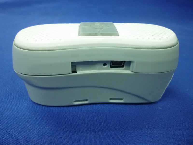
FCC ID: YMWK2XXV01 page Audix Technology (Shenzhen) Co., Ltd. Report No. ACS-F10221 15-1 15. PHOTOGRAPH OF EUT Figure 1 General Appearance of the EUT Figure 2 General Appearance of the EUT FCC ID: YMWK2XXV01 page Audix Technology (Shenzhen) Co., Ltd. Report No. ACS-F10221 15-2 Figure 3 General Appearance of the EUT Figure 4 General Appearance of the EUT FCC ID: YMWK2XXV01 page Audix Technology (Shenzhen) Co., Ltd. Report No. ACS-F10221 15-3 Figure 5 General Appearance of the EUT Figure 6 General Appearance of the EUT

ID Label/Location Info

Label Location

Internal Photos

Antenna Location

Internal Photos

FCC ID: YMWK2XXV01 page Audix Technology (Shenzhen) Co., Ltd. Report No. ACS-F10221 15-4 Figure 7 Inside of the EUT Figure 8 Inside of the EUT FCC ID: YMWK2XXV01 page Audix Technology (Shenzhen) Co., Ltd. Report No. ACS-F10221 15-5 Figure 9 Inside of the EUT Figure 10 Inside of the EUT FCC ID: YMWK2XXV01 page Audix Technology (Shenzhen) Co., Ltd. Report No. ACS-F10221 15-6 Figure 11 Inside of the EUT Figure 12 Inside of the EUT FCC ID: YMWK2XXV01 page Audix Technology (Shenzhen) Co., Ltd. Report No. ACS-F10221 15-7 Figure 13 USB Cable

RF Exposure Info

RF Exposure Statement 1. Standard Applicable According to 1.1307 (b)(1), systems operating under the provisions of this section shall be operated in a manner that ensure that the public is not exposed to radio frequency energy level in excess of the Commission’s guideline. This is a mobile device, but then in normal use, sometimes the antenna position may have a distance below 20cm from user . 2. Measurement Result: The operation frquency of this dievice is 2402MHz to 2480MHz The max peak output power is 0.06 dBm , lower than that low threshold 60/f GHz mW = (24.19 mW/13.8dBm) The SAR/MPE measurement is not necessary.

Test Report

FCC ID: YMWK2XXV01 Audix Technology (Shenzhen) Co., Ltd. Report No. ACS-F10221 APPLICATION FOR CERTIFICATION On Behalf of eComm Solutions Inc. MuziLighter Model Number: K220 FCC ID: YMWK2XXV01 Prepared for : eComm Solutions Inc. Suite 3F20, 5 Hsin-Yi Road Section 5, Taipei 11011, Taiwan Prepared By : Audix Technology (Shenzhen) Co., Ltd. No. 6, Ke Feng Rd., 52 Block, Shenzhen Science & Industrial Park, Nantou, Shenzhen, Guangdong, China Tel: (0755) 26639496 Report Number : ACS-F10221 Date of Test : Aug.05~10, 2010 Date of Report : Aug.16, 2010 FCC ID: YMWK2XXV01 Audix Technology (Shenzhen) Co., Ltd. Report No. ACS-F10221 TABLE OF CONTENTS Description Page 1. SUMMARY OF STANDARDS AND RESULTS .................................................................. 1-1 1.1. Description of Standards and Results ............................................................................................. 1-1 2. GENERAL INFORMATION .................................................................................................. 2-1 2.1. Description of Device (EUT) ......................................................................................................... 2-1 2.2. Test information ............................................................................................................................. 2-2 2.3. Tested Supporting System Details ................................................................................................. 2-2 2.4. Test Facility .................................................................................................................................... 2-3 2.5. Test Uncertainty (95% confidence levels, k=2) ............................................................................. 2-3 3. POWER LINE CONDUCTED EMISSION TEST ................................................................ 3-1 3.1. Test Equipments ............................................................................................................................. 3-1 3.2. Block Diagram of Test Setup ......................................................................................................... 3-1 3.3. Power Line Conducted Emission Test Limits ................................................................................ 3-1 3.4. Configuration of EUT on Test ....................................................................................................... 3-2 3.5. Operating Condition of EUT .......................................................................................................... 3-2 3.6. Test Procedure ................................................................................................................................ 3-2 3.7. Power Line Conducted Emission Test Results............................................................................... 3-2 4. RADIATED EMISSION TEST ............................................................................................... 4-1 4.1. Test Equipment .............................................................................................................................. 4-1 4.2. Block Diagram of Test Setup ......................................................................................................... 4-1 4.3. Radiated Emission Limit ................................................................................................................ 4-2 4.4. EUT Configuration on Test ............................................................................................................ 4-3 4.5. Operating Condition of EUT .......................................................................................................... 4-3 4.6. Test Procedure ................................................................................................................................ 4-4 4.7. Radiated Emission Test Results ..................................................................................................... 4-4 5. CONDUCTED SPURIOUS EMISSIONS .............................................................................. 5-1 5.1. Test Equipment .............................................................................................................................. 5-1 5.2. Limit ............................................................................................................................................... 5-1 5.3. Test Procedure ................................................................................................................................ 5-1 5.4. Test result ....................................................................................................................................... 5-2 6. CARRIER FREQUENCY SEPARATION TEST ................................................................. 6-7 6.1. Test Equipment .............................................................................................................................. 6-7 6.2. Limit ............................................................................................................................................... 6-7 6.3. Test Results. ................................................................................................................................... 6-7 7. 20 DB BANDWIDTH TEST .................................................................................................... 7-1 7.1. Test Equipment .............................................................................................................................. 7-1 7.2. Limit ............................................................................................................................................... 7-1 7.3. Test Results .................................................................................................................................... 7-1 8. NUMBER OF HOPPING FREQUENCY TEST ....................................................…

Text truncated - open the document above for the full version.

Test Setup Photos

FCC ID: YMWK2XXV01 page Audix Technology (Shenzhen) Co., Ltd. Report No. ACS-F10221 14-1 14. PHOTOGRAPH OF TEST 14.1.Photos of Power Line Conducted Emission Test FCC ID: YMWK2XXV01 page Audix Technology (Shenzhen) Co., Ltd. Report No. ACS-F10221 14-2 14.2.Photos of Radiated Emission Test (In Anechoic Chamber) 30~1000MHz FCC ID: YMWK2XXV01 page Audix Technology (Shenzhen) Co., Ltd. Report No. ACS-F10221 14-3 FCC ID: YMWK2XXV01 page Audix Technology (Shenzhen) Co., Ltd. Report No. ACS-F10221 14-4 Above 1000MHz

Contact Information

Applicant

Frank Lay(Mr.)
[email protected]+886.2.87804549Fax: +886.2.87804519

Technical Contact

AUDIXKen Lu
[email protected]86-755-26639497

52 Block Shenzhen Science&Industry · Shenzhen · China

Test Firm

Audix Technology (Shenzhen) Co., Ltd.Smart Tsai
[email protected]86-755-26639495Fax: 86-755-26632877

Technical Specifications

#Rule PartsFrequency RangePower Output
115C2.40 GHz - 2.48 GHz1.00 mW
Confidentiality
Long Term
Grant Notes
Power Output is Conducted.

Other Applications from eComm Solutions Inc.
All-in-One Cycling Kit - FCC ID YMWK23XX01 - eComm Solutions Inc.
YMWK23XX01

All-in-One Cycling Kit

Dec 29, 2013

Equipment Class

DSS - Part 15 Spread Spectrum Transmitter