Text extracted from the exhibit documents filed with the FCC. Open a document above to read the original.
User’s Manual – BC5100 System: BC5000 Glasses and BC100 Emitter BC100 3D Emitter Manual The BC100 3D Emitter connects a 3D-Ready TV to the BC5000 LCD Shutter Glasses for the ultimate in 3D stereoscopic viewing. This document describes the features, connection, setup, and operation of the BC100 3D Emitter. Features RF synchronization for uninterruptable 3D glasses performance Ready to watch compatibility with 3D Ready TVs equipped with a 3D Emitter Port IR sync learning capability for use with IR 3D sync based frame sequential 3D Ready TVs LED indicators assist with IR Sensor placement Management Software enables Upgrade functionality for compatibility with future 3D TVs Manual performance adjustment capability Connections 3D Ready TV with 3D Emitter Port 1: Connect the emitter to the TV using the 3D Glasses Emitter/3D SYNC Out Port as shown below. Place the BC100 3D Emitter behind the TV. 3D Ready TV with IR Emitter 1. Connect the included BC010 IR sensor to the BC100 3D Emitter. Place the IR sensor in the approximate locations shown in the image below – see the section 3D Ready TV with IR Emitter for proper placement of the IR sensor. 2. Power the BC100 3D Emitter using USB port on the 3D Ready TV. 1 : B C 0 1 0 I R S e n s o r ( s u p p l i e d ) Back or Side of TV 2: USB A to Micro B Cable (Supplied) Basic Features RF Communication of Synchronization Signal RF communications enables the BC5100 3D System to provide an awesome and uninterruptable 3D viewing experience. Line of sight obstructions, emitter placement and viewer seating arrangements have no impact on the performance of the emitter to glasses synchronization. Optimal seating distance and viewing angle is determined by the capabilities of the 3D Ready TV coupled to the BC5100 3D System. LED Indicators The BC100 3D Emitter uses 5 multicolored LEDs to indicate modes of operation or other information. The LEDs are located on the top of the emitter close to the joystick and display red, green, or orange. Joystick The BC100 3D Emitter uses a joystick to allow the user to enable various modes and change settings. The joystick has two axes and a center button function. Function of the axes and buttons are dependent on the operating mode as described in following sections. Modes of Operation The BC100 3D Emitter has 5 modes of operation. Normal IR Signal Strength Manual Tuning of Glasses Performance Pairing the BC100 with BC5000 Glasses IR Signal Search and Learning Accessing Modes During normal operation, the joystick is used to access different modes of operation. Press and hold the joystick to cycle through the available modes. Release the joystick to select a mode. In any mode, the normal mode of operation resumes after 60 seconds of inactivity. Normal Operation During normal operating mode, the BC100 3D Emitter interprets 3D signals from the TV and controls the BC5000 Series LCD Shutter Glasses through RF. No LEDs are active. IR Signal Strength Indicator The signal strength indicator provides a visual IR signal quality measurement. The number of lit green LEDs indicates the quality of the IR signal, with more green LEDs equating to better IR reception. Use this mode to determine the ideal location for placement of the IR sensor. Manual Performance Tuning The BC100 3D Emitter and BC5000 LCD Shutter Glasses are preprogrammed to work with a wide variety of TVs and 3D content. The manual performance tuning mode enables the 3D system performance to be fine tuned. Warning, use of this feature can result in improper or undesirable operation. 3D Emitter & Glasses Pairing In environments where more than one BC100 3D Emitter is present, BC5000 glasses should be paired with the emitter to ensure proper operation. This mode also involves the BC5000 glasses and is described in greater detail in a subsequent section. IR Signal Search and Learn This mode is active when the device is powered on for the first time, after a Factory Defaults reset, or when enabled using the joystick mode access. Once the BC100 3D Emitter identifies and learns a 3D IR signal, the startup sequence will only look for the previously identified IR signal. To have the BC100 3D Emitter search and learn the signals from another TV, use this mode. Factory Defaults In the event that the BC100 3D Emitter is not working properly and other troubleshooting methods have failed, use the Reset to Factory Defaults mode to attempt recovery of proper operation. Warning: Any tuning done using Manual Performance Tuning will be erased. Using the BC100 3D Emitter with 3D Sync Port Equipped TVs Use the guide in Connections: 3D Ready TV with 3D Emitter Port to properly connect the BC100 3D Emitter. When the TV is turned on, the BC100 3D Emitter will turn on as well. The LEDs will display a red moving pattern while the emitter is attempting to acquire a 3D signal and until a signal is found. If the emitter searches for a signal for longer than 60 seconds, a signal is not found. Ensure that the TV is in 3D mode. Upon finding a 3D signal, all LEDs will turn green for approximately 60 seconds and then turn off. Once the LEDs indicate a 3D signal, the BC5000 glasses can be used to experience 3D. The BC100 3D Emitter is preprogrammed and configured to operate with Sync Port equipped TVs. If the image when viewed through the BC5000 glasses is fuzzy, has ghosting, or is out of polarity, see Using the Joystick to Manually Tune Performance. Using the BC100 3D Emitter with IR 3D Sync Equipped TVs Connect the emitter and BC010 IR sensor to the TV as shown in Connections: 3D Ready TV with IR Emitter. Turn on the TV and enable 3D display. Hold the IR sensor below the TV while viewing the LEDs. While searching for and learning an IR sync signal, the LEDs will display a red moving pattern. The BC100 3D Emitter will stay in IR search mode until a signal is found and learned. If the emitter stays in search mode for longer than 60 seconds, a signal has not been located. Ensure that the TV is in 3D mode. When…
Text truncated - open the document above for the full version.
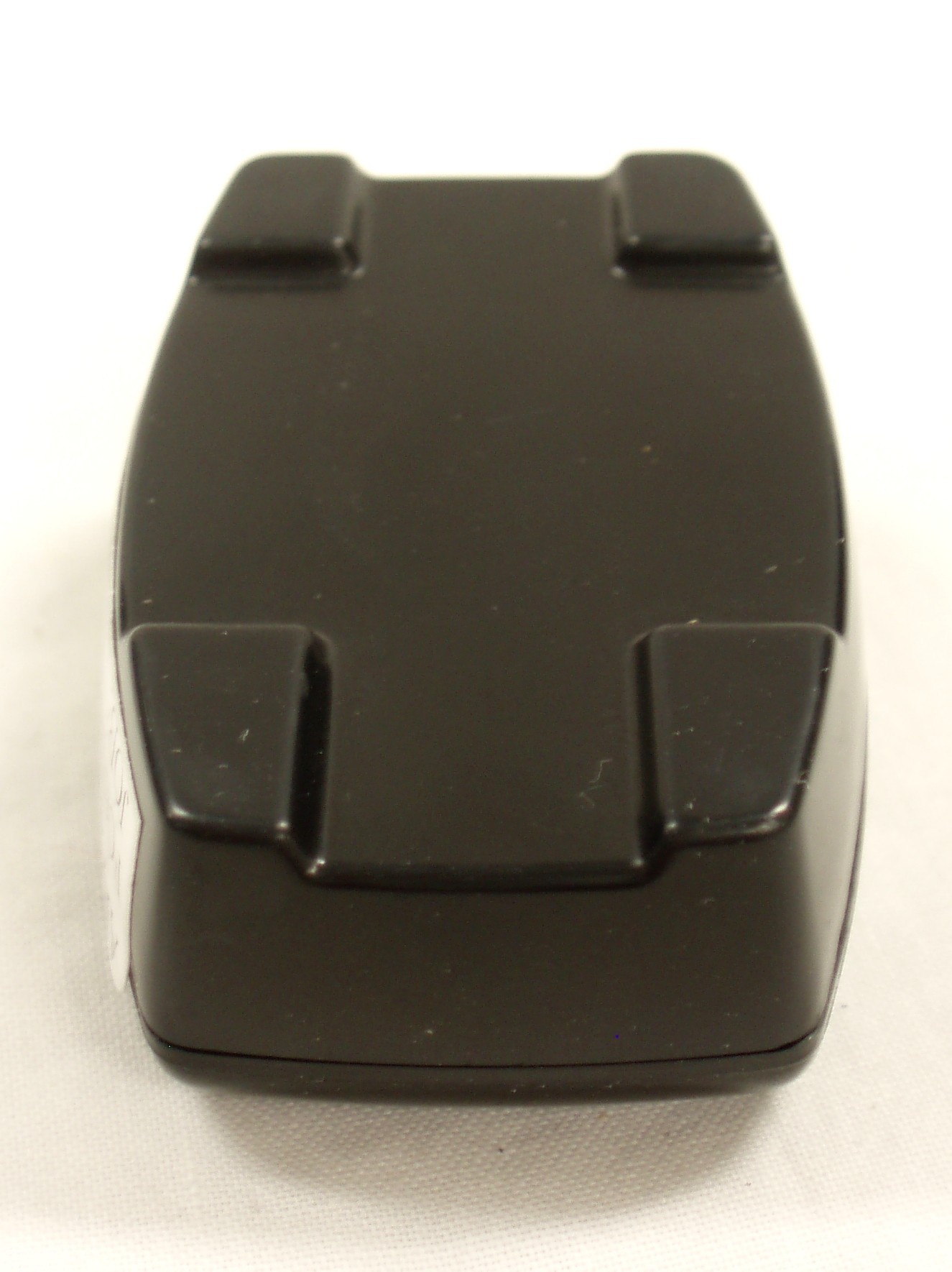
APPLICANT: BIT CAULDRON CORPORATION FCC ID: YN3-50007001 EXTERNAL PHOTOS
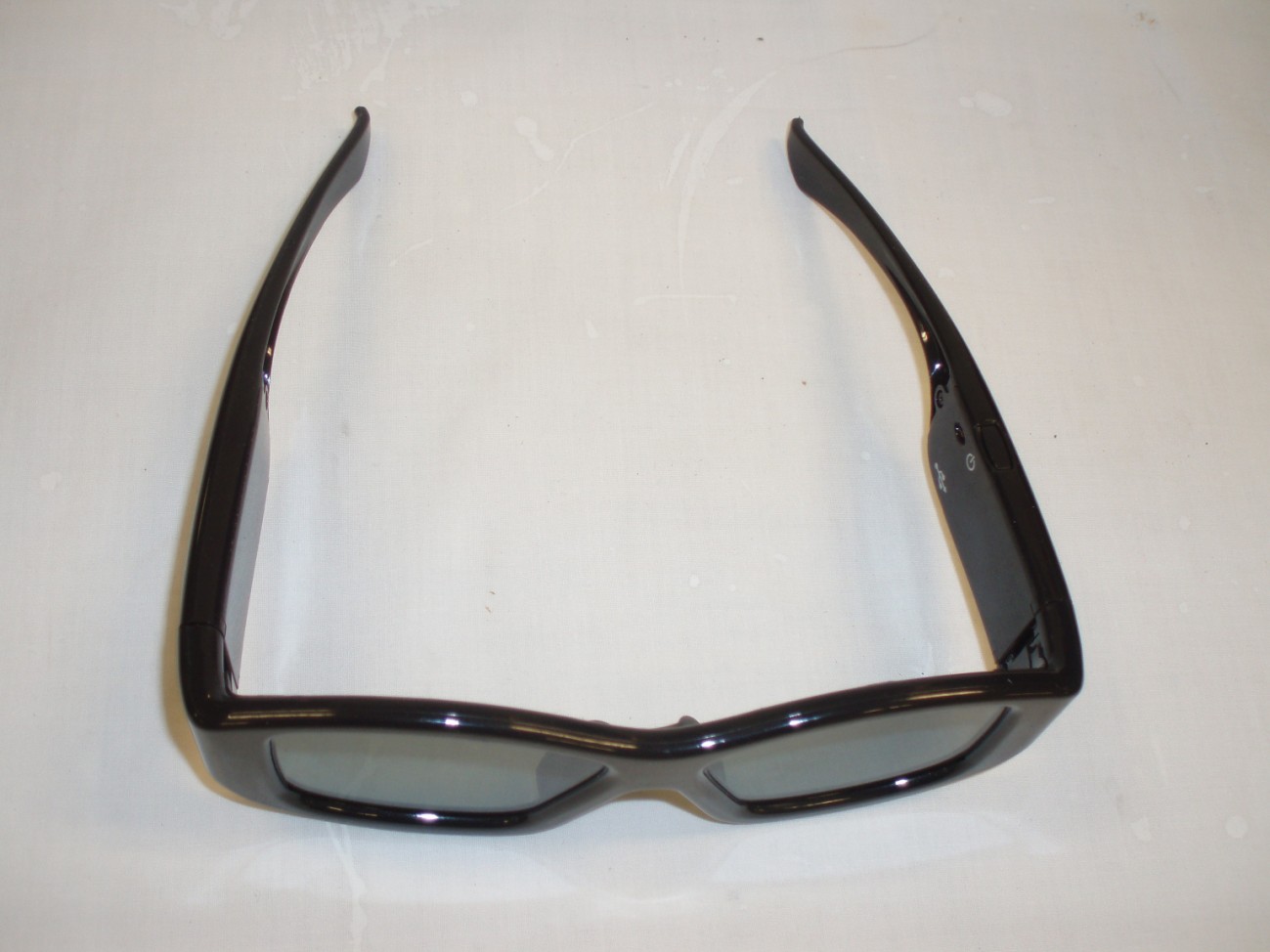
Product Markings with Monster Model Identification Figure 1. Example Marking for Monster version of Bit Cauldron's BC5000 – Due to the size and shape of this device we are placing the Label on the inside of the right temple. This portion of the device cannot be removed without breaking the device and deeming it unusable.
APPLICANT: BIT CAULDRON CORPORATION FCC ID: YN3-50007001 INTERNAL PHOTOS
CommentDescriptionDesignatorFootprintLibRefQuantity Balun CC2530 Balun CC2530 2450BM15A0002B12450BM15A00022450BM15A00021 CAP CER 1.0UF 6.3V 10% X5R 0402 CAP CER 1.0UF 6.3V 10% X5R 0402 C1, C2, C10, C11, C20, C21, C38, C411005[0402]1.0uF 04028 CAP CER 2.2UF 4V X5R 0402 CAP CER 2.2UF 4V X5R 0402C31005[0402]2.2uF 0402 4V1 CAP CER .1UF 10V 10% X5R 0402 CAP CER .1UF 10V 10% X5R 0402 C4, C5, C7, C12, C13, C141005[0402]0.1uF 04026 Cap SMD 1.0uF 0603 25V CAP CER 1UF 25V X7R 10% 0603C6, C181608[0603]1.0uF 25V 06032 Cap SMD 1.2pF 0402 HF Cap SMD 1pF 0402 HFC81005[0402]1.2pF 04021 CAP CER 220PF 50V 5% C0G 0402 CAP CER 220PF 50V 5% C0G 0402C91005[0402]220pF 04021 10pF 0402 CAP CERM 10PF 50V C0G 0402C15, C161005[0402] 10pF 50V C0G 04022 Cap SMD 27pF 0402 CAP CER 27PF 50V C0G 0402C171005[0402]22pF 04021 Cap SMD 4.7uF 0805 10V CAP CER 4.7UF 10V X7R 0805C19C08054.7uF 10V 08051 CAP 1000pF 50V 0402 CAP 1000PF 50V CERAMIC X7R 0402C391005[0402] CAP 1000pF 50V 04021 CAP 10000pF 16V 0402 CAP 10000PF 16V CERAMIC 0402 SMDC401005[0402] CAP 10000pF 16V 04021 MBR0530 DIODE SCHOTTKY 30V 500MA SOD123D1SOD-123MBR05301 LED DOT PNT 1.8MM RED LED DOT PNT 1.8MM HIEFF RED DIFFD2LED-DOT LED DOT PNT 1.8MM RED1 Chip Antenna 18pkg Chip Antenna 18pkgE12450AT18B100 Chip Antenna 18pkg1 Header 6 FlexHeader, 6-Pin. FlexJ2 5014610601 - KeepoutHeader 6 Flex1 USB Micro B R/A USB 2.0, Right Angle, SMT, Micro B Type, ReceptacleJ3USB mic ro bUSB Micro B R/A1 FILTER CHIP 1000 OHM 250MA 0402 FILTER CHIP 1000 OHM 250MA 0402L11005[0402] FILTER CHIP 1000 OHM 250MA 04021 IND 10uH LQH3 INDUCTOR 10UH 30% 630MA 1212L2LQH3NPIND 10uH LQH31 Ind 3.3nH 0402 HFInd 3.3nH 0402 HFL31005[0402]3.3nH 04021 Ind 2.7nH 0402 HFInd 2.7nH 0402 HFL41005[0402]2.7nH 04021 56.0K 0402Res 56.0K 0402R1, R34, R35, R401005[0402]56.0K 04024 RES 30.0K 0402 RES 30.0K OHM 1/ 16W 1% 0402 SMDR4, R81005[0402]RES 30.0K 04022 RES 118K 0402 RES 118K OHM 1/ 16W 1% 0402 SMDR51005[0402]RES 118K 04021 RES 1.80M 0402 RES 1.80M OHM 1/ 16W 1% 0402 SMDR6, R361005[0402]RES 1.80M 04022 160K 0402 RES 160K OHM 1/ 16W 1% 0402 SMDR7, R391005[0402]160K 04022 2.00M 0402 RES 2.00M OHM 1/ 16W 1% 0402 SMDR91005[0402]Res 2.00M 04021 1.00M 0402 RES 1.00M OHM 1/ 16W 1% 0402 SMDR101005[0402]1.00M 04021 RES 750 0402 RES 750 OHM 1/ 16W 1% 0402 SMDR331005[0402]RES 750 04021 RES 909K 0402 RES 909K OHM 1/ 16W 1% 0402 SMDR371005[0402]RES 909K 04021 SW-PB RASwitchS1PBSW RASW-PB RA1 Test Point Pin PC TEST POINT PinTP1, TP2Test Point PinTest Point Pin2 CC2530 System-on-Chip Solution for 2.4-GHz IEEE 802.15.4U1QFN-ML40_NCC25301 MC14504BDTG Hex Level Shifter for TTL-to-CMOS or CMOS-to-CMOSU2TSSOP-16MC14504BDTG1 L6924D IC BATT CHRGR ION/POLY 16- VFQFPNU3VFQFPN16 L6924D Battery Charger1 TPS61041 IC CONV DC/ DC BOOST LP SOT-23- 5U4SOT-23-5TPS610411 TPS71501 IC LDO REG ADJ 50MA MCPWR SC70-5U5SC70-LT5_NTPS7151 XTAL-32MHzCryCRYSTAL 32.000000 MHZ SMD 10PFY1NX2520CRYSTAL 32.000000 MHZ SMD 10PF1
FCC PART 15.249 AND IC RSS-210 TEST REPORT UNLICENSED INTENTIONAL RADIATOR Applicant BIT CAULDRON CORPORATION Address 1411 NW 7th Rd GAINESVILLE FL 32603 USA FCC ID YN3-50007001 IC 9186A-50007001 Model Number MonsterVision Max 3D ; BC5000 Product Description WIRELESS TRANSMITTER - GLASSES Date Sample Received 8/23/2010 Date Tested 9/7/2010 Tested By Joe Scoglio Approved By Mario R. de Aranzeta Report Number 1989AT10TestReport.doc Test Results PASS FAIL THE ATTACHED REPORT SHALL NOT BE REPRODUCED EXCEPT IN FULL WITHOUT THE WRITTEN APPROVAL OF TIMCO ENGINEERING, INC. 849 NW State Road 45 Newberry, FL 32669 USA Ph: 888.472.2424 or 352.472.5500 Fax: 352.472.2030 Email: [email protected] Website: www.timcoengr.com Certificate # 0955-01 APPLICANT: BIT CAULDRON CORPORATION FCC ID: YN3-50007001 IC: 9186A-50007001 REPORT Z:\B\BIT CAULDRON\1989AT10\1989AT10TestReport.doc Page 2 of 11 Mdea 9.20.2007 TABLE OF CONTENTS GENERAL REMARKS ..................................................................................................................... 3 GENERAL INFORMATION .............................................................................................................. 4 EMC EQUIPMENT LIST.................................................................................................................. 5 TEST PROCEDURES ...................................................................................................................... 6 RADIATION INTERFERENCE ......................................................................................................... 7 OCCUPIED BANDWIDTH ............................................................................................................... 8 BAND EDGE COMPLIANCE ........................................................................................................... 9 POWER LINE CONDUCTED INTERFERENCE .............................................................................. 11 APPLICANT: BIT CAULDRON CORPORATION FCC ID: YN3-50007001 IC: 9186A-50007001 REPORT Z:\B\BIT CAULDRON\1989AT10\1989AT10TestReport.doc Page 3 of 11 Mdea 9.20.2007 GENERAL REMARKS The attached report shall not be reproduced except in full without the written permission of Timco Engineering Inc. Summary The device under test does: fulfill the general approval requirements as identified in this test report not fulfill the general approval requirements as identified in this test report Attestations This equipment has been tested in accordance with the standards identified in this test report. To the best of my knowledge and belief, these tests were performed using the measurement procedures described in this report. All instrumentation and accessories used to test products for compliance to the indicated standards are calibrated regularly in accordance with ISO 17025 requirements. Certificate # 0955-01 I attest that the necessary measurements were made, under my supervision, at: Timco Engineering Inc. 849 NW State Road 45 Newberry, Fl 32669 Authorized Signatory Name: Mario de Aranzeta C.E.T. Compliance Engineer/ Lab. Supervisor Date: September 07, 2010 APPLICANT: BIT CAULDRON CORPORATION FCC ID: YN3-50007001 IC: 9186A-50007001 REPORT Z:\B\BIT CAULDRON\1989AT10\1989AT10TestReport.doc Page 4 of 11 Mdea 9.20.2007 GENERAL INFORMATION DUT Specification The test results relate only to the items tested. Applicable Standard Part 15.249, RSS-210 DUT Description WIRELESS TRANSMITTER - GLASSES FCC ID YN3-50007001 IC 9186A-50007001 Model Number MonsterVision Max 3D, BC5000 Operating Frequency TX: 2475.1 RX: Same No. of Channels 1 DUT Power Source 110–120Vac/50– 60Hz DC Power Battery Operated Exclusively Test Item Prototype Pre-Production Production Type of Equipment Fixed Mobile Portable Antenna Connector Fixed antenna Test Facility Timco Engineering Inc. located at 849 NW State Road 45 Newberry, FL 32669 USA. Test Conditions Temperature: 26ºC Relative humidity: 50% Test Exercise The DUT was placed in continuous transmit mode of operation. Modifications None Test Supporting Equipment Supporting Device Manufacturer Model / FCC ID Serial Number N/A APPLICANT: BIT CAULDRON CORPORATION FCC ID: YN3-50007001 IC: 9186A-50007001 REPORT Z:\B\BIT CAULDRON\1989AT10\1989AT10TestReport.doc Page 5 of 11 Mdea 9.20.2007 EMC EQUIPMENT LIST Device Manufacturer Model Serial Number Cal/Char Date Due Date 3-Meter Semi- Anechoic Chamber Panashield N/A N/A Listed 3/10/10 3/10/12 AC Voltmeter HP 400FL 2213A14499 CAL 3/23/09 3/23/11 Antenna: Dipole Kit Electro- Metrics TDA-30/1-4 153 CHAR 6/10/09 6/10/11 Frequency Counter HP 5385A 3242A07460 CAL 5/26/09 5/26/11 Hygro- Thermometer Extech 445703 0602 CAL 1/30/09 1/30/11 Modulation Analyzer HP 8901A 3435A06868 CAL 5/26/09 5/26/11 Digital Multimeter Fluke FLUKE-77-3 79510405 CAL 5/18/09 5/18/11 Analyzer Tan Tower Preamplifier HP 8449B-H02 3008A00372 CAL 11/21/09 11/21/11 Analyzer Tan Tower Quasi- Peak Adapter HP 85650A 3303A01690 CAL 11/22/09 11/22/11 Analyzer Tan Tower RF Preselector HP 85685A 3221A01400 CAL 11/21/09 11/21/11 Analyzer Tan Tower Spectrum Analyzer HP 8566B Opt 462 3138A07786 3144A20661 CAL 11/24/09 11/24/11 Temperature Chamber Tenney Engineering TTRC 11717-7 CHAR 4/25/10 4/25/12 APPLICANT: BIT CAULDRON CORPORATION FCC ID: YN3-50007001 IC: 9186A-50007001 REPORT Z:\B\BIT CAULDRON\1989AT10\1989AT10TestReport.doc Page 6 of 11 Mdea 9.20.2007 TEST PROCEDURES Radiation Interference: ANSI C63.4-2003 using a spectrum analyzer, a preselector, a quasi- peak adapter, and an appropriate antenna. The analyzer was calibrated in dB above a microvolt at the output of the antenna. The resolution bandwidth was 100 kHz with an appropriate sweep speed and the video bandwidth was 300 kHz up to 1 GHz and 1 MHz with a video BW of 3 MHz above 1 GHz. When an emission was found, the table was rotated to produce the maximum signal strength. The antenna was placed in both the horizontal and vertical planes and the worse case emissions were reported. The spectrum…
Text truncated - open the document above for the full version.
| # | Rule Parts | Frequency Range | Power Output |
|---|---|---|---|
| 1 | 15C | 2.48 GHz - 2.48 GHz | - |

WIRELESS TRANSMITTER-EMITTER
Equipment Class
DXX - Part 15 Low Power Communication Device Transmitter