YOPGS2100MIPUltra-Low Power Wi-Fi Module
Gainspan Corporation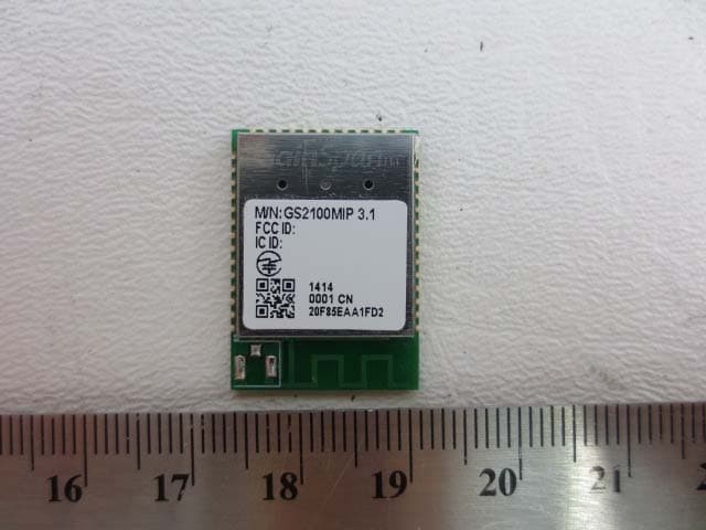
Click to zoom
Application Details
- Equipment Class
- DTS - Digital Transmission System
- Date of Grant
- Jun 24, 2014
- Application Purpose
- Original Equipment
- Date of Application
- Jun 24, 2014
- Equipment Note
- Ultra-Low Power Wi-Fi Module
- Frequency Range
- 2412.00000000 - 2462.00000000
- Company
- Gainspan Corporation
- Country
- United States
Documents & Files
Document Text
Text extracted from the exhibit documents filed with the FCC. Open a document above to read the original.
Users Manual
Release 0.10, 04/08/2014 Copyright © 2014 GainSpan. All rights reserved. Preliminary Confidential GS2100M Low Power WiFi Module Data Sheet GS2100M-DS-001212 GainSpan ® 802.11b/g/n Low Power WiFi ® Series Modules FCC Communications Commission (FCC) Interference Statement This equipment has been tested and found to comply with the limits for a Class B digital device, pursuant to Part 15 of the FCC Rules. These limits are designed to provide reasonable protection against harmful interference in a residential installation. This equipment generates uses and can radiate frequency energy and, if not installed and used in accordance with the instructions may cause harmful interference to radio communications. However, there is no guarantee that interference will not occur in a particular installation. If this equipment does cause harmful interference to radio or television reception, which can be determined by turning the equipment off and on, the user is encouraged to try to correct the interference by one of the following measures: •Reorient or relocate the receiving antenna •Increase the separation between the equipment and receiver •Connect the equipment into an outlet on a circuit different from that to which the receiver is connected •Consult the dealer or an experienced radio/TV technician for help FCC Caution: To assure continued compliance, (example - use only shielded interface cables when connecting to computer or peripheral devices). Any changes or modifications not expressly approved by the party responsible for compliance could void the user’s authority to operate this equipment. This device complies with Part 15 of the FCC Rules. Operation is subject to the following two conditions: (1) This device may not cause harmful interference, and (2) this device must accept any interference received, including interference that may cause undesired operation. FCC & IC Radiation Exposure Statement This equipment complies with FCC & IC radiation exposure limits set forth for an uncontrolled environment. This equipment should be installed and operated with minimum distance 20cm between the radiator & your body. This transmitter must not be co-located or operating in conjunction with any other antenna or transmitter must not be co-located or operating in conjunction with any other antenna or transmitter. This device intended only for OEM integrators under the following conditions: 1.The antenna must be installed such that 20cm is maintained between the antenna and users, and 2.The transmitter module may not be co-located with any other transmitter or antenna. As long as 2 conditions above are met, further transmitter test will not be required. However, the OEM integrator is still responsible for testing their end-product for any additional compliance requirements required with this module installed (for example, digital device emissions, PC peripheral requirements, etc.). IMPORTANT NOTE: In the event that these conditions cannot be met (for example certain laptop configurations or co-location with another transmitter), then the FCC & IC authorizations are no longer considered valid and the FCC & IC IDs cannot be used on the final product. In these circumstances, the OEM integrator will be responsible for re-evaluating the end product (including the transmitter) and obtaining separate FCC & IC authorizations. End Product Labeling: This transmitter module is authorized only for use in device where the antenna may be installed such that 20cm may be maintained between the antenna and users (for example access points, routers, wireless ADSL modems, and similar equipment). the final product must be labeled in a visible area with the corresponding FCC ID number. IC Certification - CanadaThe labeling requirements for Industry Canada are similar to those of the FCC. A visible label on the outside of the final product must display the IC labeling. The user is responsible for the end product to comply with IC ICES-003 (Unintentional radiators). English This device complies with Industry Canada license-exempt RSS standard(s). Operation is subject to the following two conditions: 1.This device may not cause harmful interference 2.This device must accept any interference received, including received, including interference that may cause undesired operation of the device. French Cet appareil est conforme à Industrie Canada une licence standard RSS exonérés (s). Son fonctionnement est soumis aux deux conditions suivantes: 1.Cet appareil ne doit pas provoquer d'interférences 2.Cet appareil doit accepter toute interférence reçue, y compris les interférences pouvant provoquer un fonctionnement indésirable de l'appareil. Manual Information That Must be Included The user’s manual for end users must include the following information in a prominent location. IMPORTANT NOTE: To comply with FCC & IC RF exposure compliance requirements, the antenna used for this transmitter must be installed to provide a separation distance of at least 20cm from all persons and must not be co-located or operating in conjunction with any other antenna or transmitter. Additional Notations: GainSpan modules have been built or under development for near body exposure applications. The 20cm statement is a standard note because absorption rate testing (commonly knowns as SAR or Specific absorption rate) is not modularly transferable for FCC/IC. Thus, if a radio is being used against the body, the end user is still responsible to test for regulatory near body exposure testing (for USA, please refer to the following): •FCC Part 1.1037 •FCC Part 2.1091 Mobile Devices •FCC Part 2.1093 Portable Devices •FCC Part 15.247 (b) (4) Copyright StatementThis GainSpan manual is owned by GainSpan or its licensors and protected by U.S. and international copyright laws, conventions, and treaties. Your right to use this manual is subject to limitations and restrictions imposed by applicable licenses and copyright laws. Unauthorized reproduction, modification,…
Text truncated - open the document above for the full version.
External Photos
GainSpan Corporation FCC ID: YOPGS2100MIP IC: 9154A-GS2100MIP Report Number: R1404032-247 Rev A Page 64 of 66 FCC Part 15C/IC RSS-210 Test Report 16 Exhibit C – EUT Photographs 16.1 EUT - Front View 16.2 EUT - Back View
ID Label/Location Info
3.2 PRODUCT LABEL & PHOTOS, GS2100MIP FRONT VIEW BACK VIEW IC: 9154A-GS2100MIP 211-140505
Internal Photos
GainSpan Corporation FCC ID: YOPGS2100MIP IC: 9154A-GS2100MIP Report Number: R1404032-247 Rev A Page 65 of 66 FCC Part 15C/IC RSS-210 Test Report 16.3 EUT with Supporting Board View 16.4 EUT – Front Unshielded GainSpan Corporation FCC ID: YOPGS2100MIP IC: 9154A-GS2100MIP Report Number: R1404032-247 Rev A Page 66 of 66 FCC Part 15C/IC RSS-210 Test Report 16.5 EUT – Power Supply View --- END OF REPORT ---
RF Exposure Info
GainSpan Corporation FCC ID: YOPGS2100MIP IC: 9154A-GS2100MIP Report Number: R1404032-247 Rev A Page 10 of 66 FCC Part 15C/IC RSS-210 Test Report 4 FCC §15.247 (i), §2.1091 & IC RSS-102 – RF Exposure 4.1 Applicable Standard According to FCC §15.247(i) and §1.1307(b)(1), systems operating under the provisions of this section shall be operated in a manner that ensures that the public is not exposed to radio frequency energy level in excess of the Commission’s guidelines. Limits for General Population/Uncontrolled Exposure Frequency Range (MHz) Electric Field Strength (V/m) Magnetic Field Strength (A/m) Power Density (mW/cm 2 ) Averaging Time (minutes) Limits for General Population/Uncontrolled Exposure 0.3-1.34 614 1.63 * (100) 30 1.34-30 824/f 2.19/f * (180/f 2 ) 30 30-300 27.5 0.073 0.2 30 300-1500 / / f/1500 30 1500-100,000 / / 1.0 30 f = frequency in MHz * = Plane-wave equivalent power density Before equipment certification is granted, the procedure of IC RSS-102 must be followed concerning the exposure of humans to RF fields. According to IC RSS-102 Issue 2 section 4.1, RF limits used for general public will be applied to the EUT. Frequency Range (MHz) Electric Field (V/m rms) Magnetic Field (A/m rms) Power Density (W/m 2 ) Time Averaging (min) 0.003 - 1 280 2.19 - 6 1 - 10 280 / f 2.19 / f - 6 10 - 30 28 2.19 / f - 6 30 – 300 28 0.073 2* 6 300 – 1 500 1.585 f 0.5 0.0042 f 0.5 f / 150 6 1 500 – 15 000 61.4 0.163 10 6 15 000 – 150 000 61.4 0.163 10 616000 / f 1.2 150 000- 300 000 0.158 f 0.5 4.21 x 10 -4 f 0.5 6.67 x 10 -5 f 616000 / f 1.2 Note: ƒ is frequency in MHz * = Power density limit is applicable at frequencies greater than 100 MHz GainSpan Corporation FCC ID: YOPGS2100MIP IC: 9154A-GS2100MIP Report Number: R1404032-247 Rev A Page 11 of 66 FCC Part 15C/IC RSS-210 Test Report 4.2 MPE Prediction Predication of MPE limit at a given distance, Equation from OET Bulletin 65, Edition 97-01 S = PG/4R² Where: S = power density P = power input to antenna G = power gain of the antenna in the direction of interest relative to an isotropic radiator R = distance to the center of radiation of the antenna 4.3 MPE Results Maximum peak output power at antenna input terminal (dBm): 19.57 Maximum peak output power at antenna input terminal (mW): 90.5732 Prediction distance (cm): 20 Prediction frequency (MHz): 2412 Maximum Antenna Gain, typical (dBi): 2.26 Maximum Antenna Gain (numeric): 1.682674 Power density of prediction frequency at 20.0 cm (mW/cm 2 ): 0.03032 Power density of prediction frequency at 20.0 cm (W/m 2 ): 0.3032 MPE limit for uncontrolled exposure at prediction frequency (mW/cm 2 ): 1.0 MPE limit for uncontrolled exposure at prediction frequency (W/m 2 ): 10 The device is compliant with the requirement MPE limit for uncontrolled exposure. The maximum power density at the distance of 20 cm is 0.03032 mW/cm 2 (0.3032 W/m 2 ).Limit is 1.0 mW/cm 2 (10 W/m 2 ).
Test Report
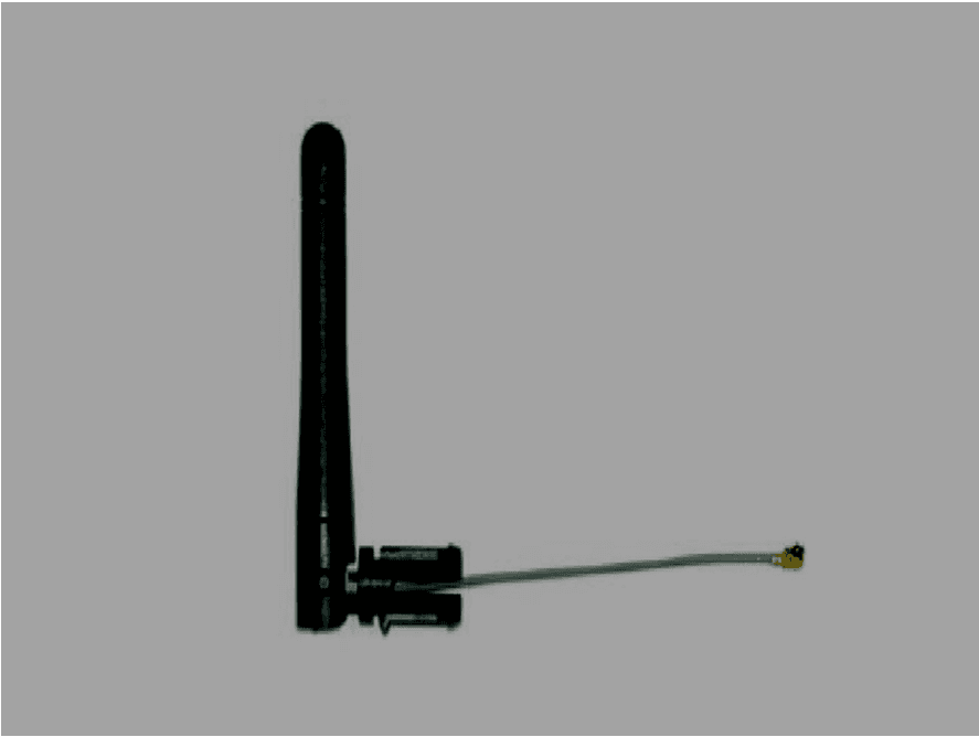
Note: This test report is prepared for the customer shown above and for the device described herein. It may not be duplicated or used in part without prior written consent from Bay Area Compliance Laboratories Corp. This report must not be used by the customer to claim product certification, approval, or endorsement by A2LA*, NIST, or any agency of the Federal Government. * This report may contain data that are not covered by the A2LA accreditation and are marked with an asterisk “*” (Rev.2) FCC PART 15 SUBPART C IC RSS-210, ISSUE 8, DECEMBER 2010 TEST AND MEASUREMENT REPORT For GainSpan Corporation 3590 N. First Street, Suite 300, San Jose, CA 95134, USA Report Type: Original Report Product Type: 802.11 b/g/n20 Wi-Fi Module Prepared By Glenn Escano Report Number R1404032-247 Rev A Report Date 2014-06-17 Reviewed By Bo Li Test En gineer Bay Area Compliance Laboratories Corp. 1274 Anvilwood Avenue, Sunnyvale, CA 94089, USA Tel: (408) 732-9162 Fax: (408) 732-9164 FCC ID: YOPGS2100MIP IC: 9154A-GS2100MIP GainSpan Corporation FCC ID: YOPGS2100MIP IC: 9154A-GS2100MIP Report Number: R1404032-247 Rev A Page 2 of 66 FCC Part 15C/IC RSS-210 Test Report TABLE OF CONTENTS 1 General Description ..................................................................................................................................................... 5 1.1 Product Description for Equipment Under Test (EUT) ...................................................................................... 5 1.2 Mechanical Description of EUT ......................................................................................................................... 5 1.3 Objective ............................................................................................................................................................. 5 1.4 Related Submittal(s)/Grant(s) ............................................................................................................................. 5 1.5 Test Methodology ............................................................................................................................................... 5 1.6 Measurement Uncertainty ................................................................................................................................... 5 1.7 Test Facility ........................................................................................................................................................ 6 2 System Test Configuration.......................................................................................................................................... 7 2.1 Justification ......................................................................................................................................................... 7 2.2 EUT Exercise Software....................................................................................................................................... 7 2.3 Special Equipment .............................................................................................................................................. 7 2.4 Equipment Modifications.................................................................................................................................... 7 2.5 Local Support Equipment ................................................................................................................................... 7 2.6 EUT Internal Configuration Details .................................................................................................................... 7 2.7 Interface Ports and Cables .................................................................................................................................. 8 2.8 External I/O Cabling List and AC Cord .............................................................................................................. 8 2.9 Power Supply List and Details ............................................................................................................................ 8 3 Summary of Test Results ............................................................................................................................................ 9 4 FCC §15.247 (i), §2.1091 & IC RSS-102 – RF Exposure .......................................................................................... 10 4.1 Applicable Standard .......................................................................................................................................... 10 4.2 MPE Prediction ................................................................................................................................................. 11 4.3 MPE Results ..................................................................................................................................................... 11 5 FCC §15.203 & IC RSS-Gen §7.1.2 – Antenna Requirements ................................................................................ 12 5.1 Applicable Standard .......................................................................................................................................... 12 5.2 Antenna List ...................................................................................................................................................... 12 6 FCC §15.207 & IC RSS-Gen §7.2.4 – AC Line Conducted Emissions .................................................................... 13 6.1 Applicable Standards ........................................................................................................................................ 13 6.2 Test Setup ......................................................................................................................................................... 13 6.3 Test Procedure ..................................................................................…
Text truncated - open the document above for the full version.
Test Setup Photos
GainSpan Corporation FCC ID: YOPGS2100MIP IC: 9154A-GS2100MIP Report Number: R1404032-247 Rev A Page 61 of 66 FCC Part 15C/IC RSS-210 Test Report 15 Exhibit B – Test Setup Photographs 15.1 AC Line Conducted Emission – Front View 15.2 AC Line Conducted Emission – Side View GainSpan Corporation FCC ID: YOPGS2100MIP IC: 9154A-GS2100MIP Report Number: R1404032-247 Rev A Page 62 of 66 FCC Part 15C/IC RSS-210 Test Report 15.3 Radiated Emission Front View at 3 Meter – EUT 15.4 Radiated Emission below 1 GHz Rear View at 3 Meter GainSpan Corporation FCC ID: YOPGS2100MIP IC: 9154A-GS2100MIP Report Number: R1404032-247 Rev A Page 63 of 66 FCC Part 15C/IC RSS-210 Test Report 15.5 Radiated Emission above 1 GHz Rear View at 3 Meter
Contact Information
Applicant
Paolomaria Schiratti(VP Global Certification)
Test Firm
Bay Area Compliance Laboratories Corp.Lisa Tang
Technical Specifications
| # | Rule Parts | Frequency Range | Power Output |
|---|---|---|---|
| 1 | 15C | 2.41 GHz - 2.46 GHz | 90.60 mW |
Other Applications from Gainspan Corporation
YOPGS2100MIE
Jun 21, 2014Ultra-Low Power Wi-Fi Module
Equipment Class
DTS - Digital Transmission System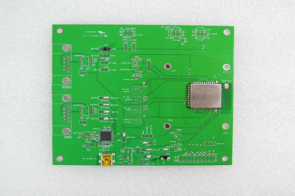
YOPGS1011MEPS
Aug 12, 2012WIFI MODULE
Equipment Class
DTS - Digital Transmission System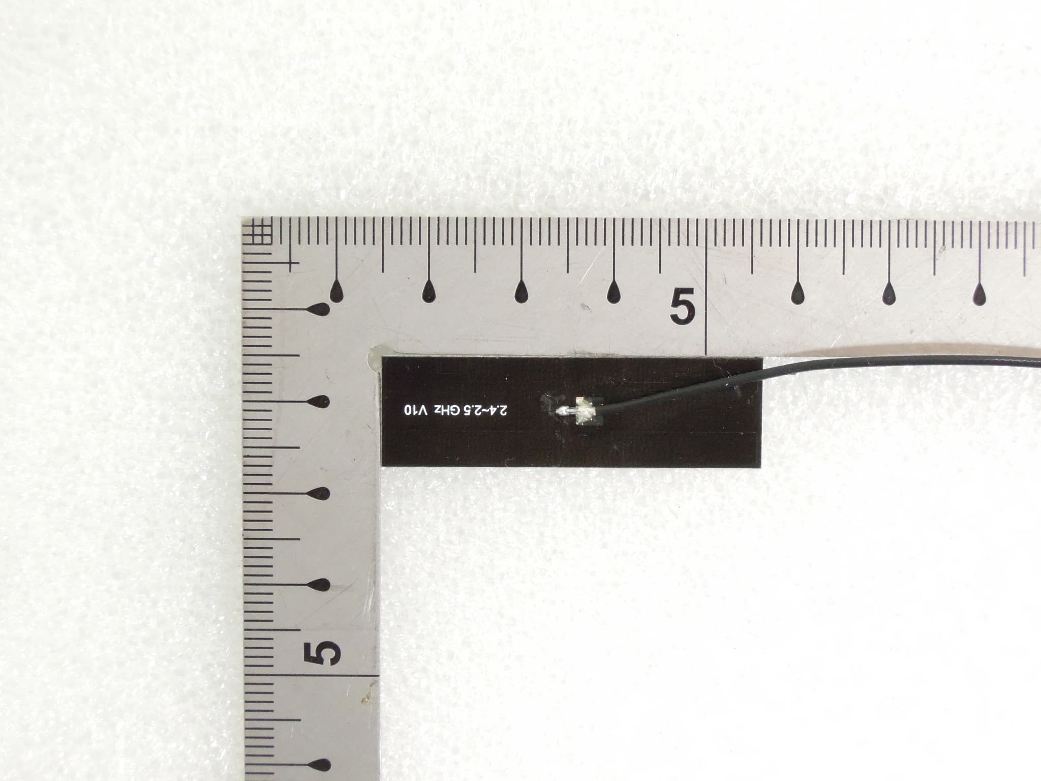
YOPGS1011MIES
Aug 12, 2012WIFI MODULE
Equipment Class
DTS - Digital Transmission System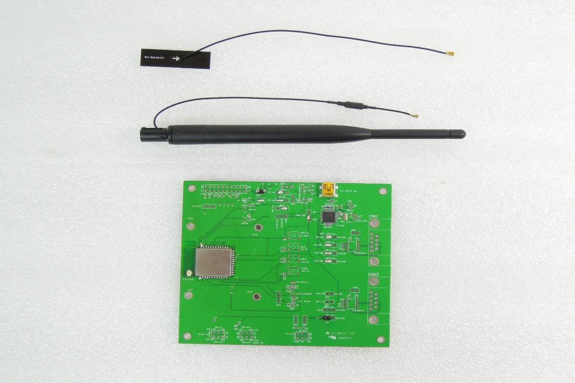
YOPGS1011MEES
Aug 12, 2012WIFI MODULE
Equipment Class
DTS - Digital Transmission System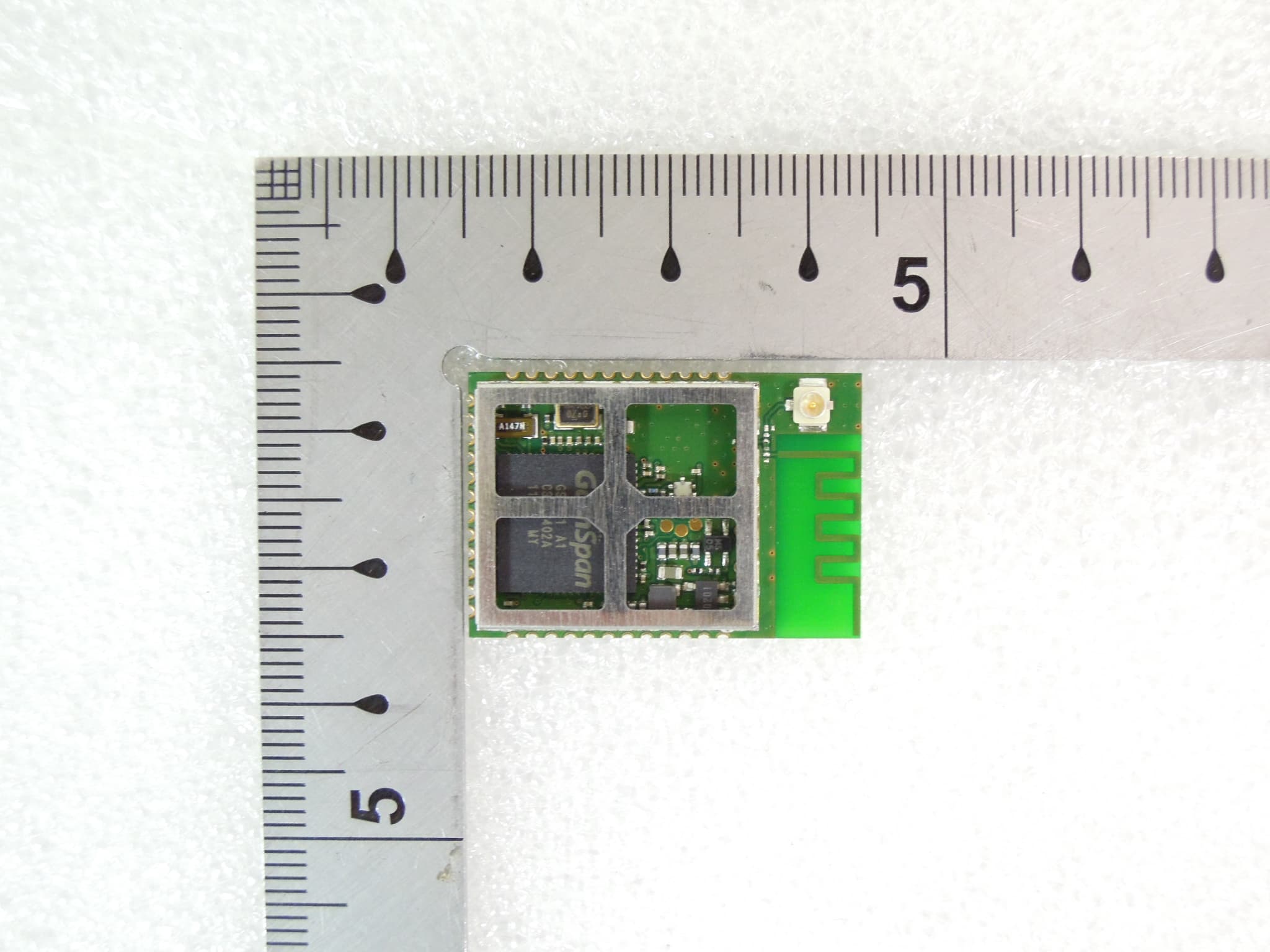
YOPGS1011MIPS
Aug 12, 2012WIFI MODULE
Equipment Class
DTS - Digital Transmission System