YP3-IT-109J001Dual Band Repeater
INNERTRON, INC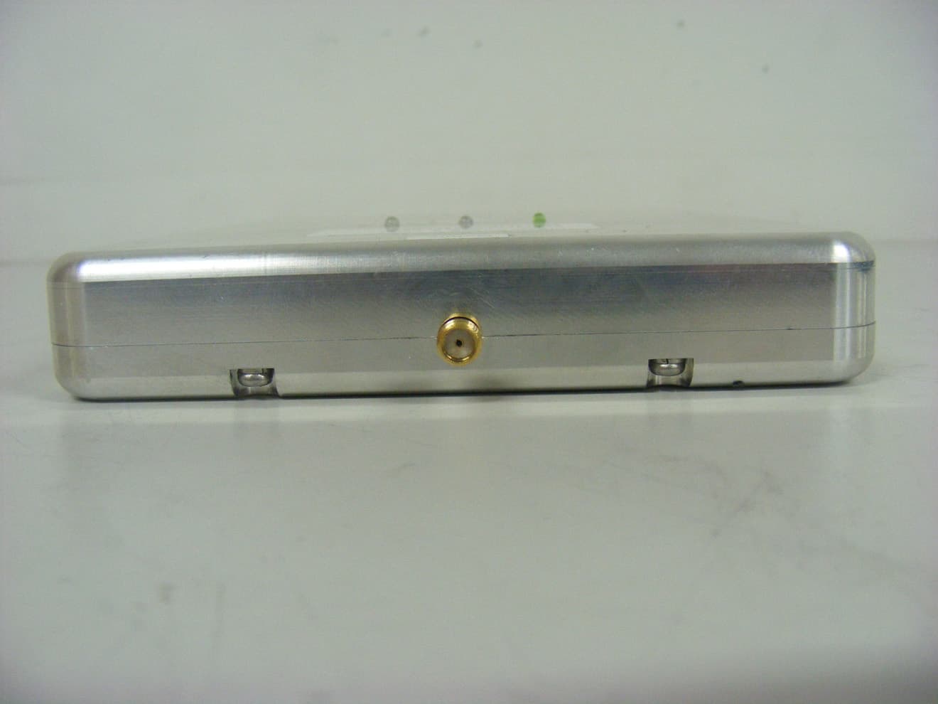
Click to zoom
Application Details
- Equipment Class
- PCB - PCS Licensed Transmitter
- Date of Grant
- Dec 21, 2010
- Application Purpose
- Original Equipment
- Date of Application
- Dec 20, 2010
- Equipment Note
- Dual Band Repeater
- Frequency Range
- 1930.00000000 - 1990.00000000
- Company
- INNERTRON, INC
- Country
- South Korea
Documents & Files
Document Text
Text extracted from the exhibit documents filed with the FCC. Open a document above to read the original.
Users Manual
Cellular/PCS Repeater Installation and Operation manual Innertron, Inc. www.Innertron.com Best Call Cellular/PCS Repeater Installation and Operation Manual Innertron, Inc. 96B 5L 663-4 Gojan-dong, Namdong-gu, Incheon-city 405-310 Korea Phone : +82-32-816-1456 / 1458 Fax : +82-32-816-1457 Mobile : +82-10-6602-6980 Website: www.innertron.com Email: [email protected] Cellular/PCS Repeater Installation and Operation manual Congratulations on the purchase of our Best Call Cellular/PCS Repeater! Safety First _ For your safety and to prevent injury to the installer or the operator, it is essential to read this manual carefully before your new unit is installed and operated. _ Through out this document this symbol indicates potential injury incase the operator fails to follow the guideline or common sense during the installation of the repeater unit. Personal safety _ This unit is powered by small AC adaptor unit. Turn off the electricity supply if you have to do any rewiring or making alterations to wall sockets. _ The equipment should be used only for amplifying mobile (cellular) phone signals and not for any other purpose. _ Should the unit fail to operate, any repairs should be carried out by qualified personnel ONLY. _ The RF energy that the unit radiates is very small (max of 5mW) this level is many times smaller than the RF power radiated by your mobile phone. General Repeater Information Introduction Almost all of us have experienced a dropped call or “Service Not Available” messages on our cell phones. This phenomenon occurs because there is inadequate signal strength from the cellular/PCS towers that provide network coverage. You see the base station cellular/PCS towers along roadsides, on top of communications towers, and installed on some buildings in urban areas. Often transmission to and reception from a cellular/PCS tower is weak because the tower is such a long way away from the mobile unit. Cellular/PCS Repeater Installation and Operation manual Innertron, Inc. www.Innertron.com Other times, buildings block the Cellular/PCS signal or make it patchy. Full coverage is quite rare, and due to “poor reception” we experience interruption of conversations, voice distortion and dropped calls. The Best Call Cellular/PCS Repeater is the solution to this problem. Repeaters not only amplify the weak received signal, but they also reduce the need for high level of RF transmission from your cell-phone, reducing undesirable radiation exposure and battery drainage. The Best Call Cellular/PCS Repeater is ideal for areas such as offices, apartment blocks and homes where your phone is ordinarily unable to get adequate reception. By boosting the signal, this device enhances the signal from your handset, ensuring a reduction in noise and call drops, and so better quality of service. So how does it work? Look at the image on the next page to understand the setup of the Best Call Cellular/PCS Repeater kit. The repeater is made up of two main parts: the directional panel antenna and the Best Call amplifier unit. The directional panel antenna is aligned with the closest cell phone tower, and collects the Cellular/PCS signal. This signal is then sent via a 30-foot cable to the Best Call amplifier unit. The amplifier unit boosts the signal, and then retransmits it about your home or office using a monopole broadcast antenna. Best Call Repeater Kit Contents 1. Best Call Amplifier Unit 2. Cellular/PCS Monopole Antenna Unit 3. Celluar/PCS Directional Panel Antenna Unit (and Fixtures) 4. DC Adapter (3.8V) 5. Antenna Cable 6. Cable Wrench Installing your Best Call Repeater Site Selection The first thing you need to do before installing your Best Call Repeater is to find out where you want to install the repeater. Look at the diagram below for an idea of how the Cellular/PCS Repeater works: 1. The Cellular/PCS signal is broadcast to/from the Cellular/PCS tower. 2. The directional panel antenna collects the signal from the Cellular/PCS tower. 3. The Best Call Repeater amplifies the signal and re-broadcasts it about your home/office. 4. Ideally, the Best Call Amplifier Unit and the monopole broadcast Cellular/PCS Repeater Installation and Operation manual Innertron, Inc. www.Innertron.com Step 1 – Locating the Cellular/PCS Signal The best way to find the best Cellular/PCS signal around your home/office is simply to walk around with your cell phone on. You should use a cell phone on the network/band whose signal you are trying to improve. The “Signal Strength” meter on your cell phone will tell you where the signal is strongest. Note: The Cell Phone “Signal Strength” meter takes up to 30 seconds to update as you move from location to location, so make sure to take a nice long pause in every location you test. The place you choose should either be outside, or in the very least by a window. It should also be within 30 feet of where you want to rebroadcast the Cellular/PCS signal (this is the length of the provided cable). Step 2 – Set up the Cellular/PCS Repeater Once you have established what part of your home has the best signal, you will need to set up the Best Call Cellular/PCS Repeater. 1. Place the panel antenna in the place with the best signal and connect it to the 30 foot cable. 2. Connect the other end of the cable to the connector on the bottom side of the Best Call Amplifier Unit (marked “BTS”). 3. Finally, connect the monopole broadcast antenna to the connector on top of the Best Call repeater (marked “SERVICE”). 4. Move the Best Call amplifier unit inside to where you want the signal to be rebroadcast. Try to make sure that the directional panel antenna and Best Call amplifier unit are as far away from each other as possible, and separated by a wall if at all possible. Point 4 above is very important because it provides isolation between the directional panel antenna and the monopole broadcast antenna. The two antennas need to be isolated from one another in order to prevent feedback/oscillation (thi…
Text truncated - open the document above for the full version.
Cover Letter(s)
INNERTRON, INC 96 Block 5Lot 663-4 Gojandong, Namdong-gu, Incheon City, South Korea Date: November 16, 2010 Federal Communications Commission 7435 Oakland Mills Road Columbia MD 21046 c.c. UL Compliance Certification Services Certification Division 47173 Benicia Street Fremont, CA 94538, USA To whom it may concern: I, the undersigned, hereby authorize Lab Manager Jim. Kim and of SGS Testing Korea Co., Ltd and hereafter referred to as SGS Testing Korea, to act on our behalf in all manners relating to application for equipment authorization, including signing of all documents relating to these matters. Any and all acts carried out by Lab Manager Jim. Kim of SGS Testing Korea Co., Ltd on our behalf shall have the same effect as acts of our own. I, the undersigned, hereby certify that we are not subject to a denial of federal benefits, that includes FCC benefits, pursuant to Section 5301 of the Anti-Drug Abuse Act of 1988, 21 U.S.C. 853(a). In authorizing SGS Testing Korea as our agent, we still recognize that we are responsible to: a) comply with the relevant provisions of the certification program; b) make all necessary arrangements for the conduct of the evaluation, including provision for examining documentation and access to all areas, records (including internal audit reports) and personnel for the purposes of evaluation (e.g. testing, inspection, assessment, surveillance, reassessment) and resolution of complaints; c) make claims regarding certification only in respect of the scope for which certification has been granted; d) do not use our product certification in such a manner as to bring the Certification Division into disrepute and not make any statement regarding our product certification which the Certification Division may consider misleading or unauthorized; e) upon suspension or cancellation of certification, discontinue use of all advertising matter that contains any reference thereto and return any certification documents as required by the Certification Division; INNERTRON, INC 96 Block 5Lot 663-4 Gojandong, Namdong-gu, Incheon City, South Korea f) use certification only to indicate the products are certified as being in conformity with specified standards; g) endeavor to ensure that no certificate or report nor any part thereof is used in a misleading manner; h) ensure that any reference to our product certification in communication media such as documents, brochures or advertising, complies with the requirements of the Certification Division; i) keep a record of all complaints made known to the us relating to the product’s compliance with requirements of the relevant standard and to make these records available to the Certification Division when requested; j) take appropriate action with respect to such complaints and any deficiencies found in products or services that affect compliance with the requirements for certification; k) document the actions taken. This authorization is valid until further written notice from the applicant. Sincerely Yours, Jong Woo Ha / Manager INNERTRON, INC
Cover Letter(s)
INNERTRON, INC 96 Block 5Lot 663-4 Gojandong, Namdong-gu, Incheon City, South Korea Federal Communications Commission 7435 Oakland Mills Road Columbia, MD 21046 Gentlemen: This letter is to comply with Section 0.457(d)(2)(i) and 0.459 pertaining to confidential material. We, INNERTRON, INC., would like the following documents regarding this submission for FCC ID: YP3-IT-109J001 to be kept confidential. 1. Schematics 2. Operating description 3. Block Diagram 4. Tune-up Procedure 5. Parts List The above material contains trade secrets or technical data, which would customarily be guarded from competitors. We do not want these documents to be accessible to the general public. Sincerely, Jong Woo Ha / Manager INNERTRON, INC
External Photos
External photos of EUT Front view of EUT Rear view of EUT Side view of EUT Top view of EUT Bottom view of EUT
ID Label/Location Info
FCC Label (Dual Band Repeater) 1. FCC Label Drawing 2. FCC Label location INNERTRON, INC Model : Dual Band Repeater FCC ID : YP3-IT-109J001 Made in Korea
Internal Photos
Internal photos of EUT Inner view of Main PCB Top view of Main PCB Bottom view of Main PCB Top view of LCD Bottom view of LCD
Test Report
Report Number: F690501/RF-RTL004286 Page: 2 of 59 The results shown in this test report refer only to the sample(s) tested unless otherwise stated. This test report cannot be reproduced, except in full, without prior written permission of the Company. SGS Testing Korea Co., Ltd. 18-34, Sanbon-dong, Gunpo-si, Gyeonggi-do, Korea, 435-040 Tel. +82 31 428 5700 / Fax. +82 31 427 2371 www.electrolab.kr.sgs.com INDEX TABLE OF CONTENTS Page 1. General Information ---------------------------------------------------------------------------------------3 2. RF Output Power ------------------------------------------------------------------------------------------6 3. Occupied Bandwidth 26 ㏈ ---------------------------------------------------------------------------- 16 4. Spurious Emissions At Antenna Terminal -----------------------------------------------------------24 5. Band Edge --------------------------------------------------------------------------------------------------37 6. Field Strength of Spurious Radiation -----------------------------------------------------------------46 7. Frequency Stability --------------------------------------------------------------------------------------- 53 8. RF Exposure Evaluation -------------------------------------------------------------------------------- 58 Report Number: F690501/RF-RTL004286 Page: 3 of 59 The results shown in this test report refer only to the sample(s) tested unless otherwise stated. This test report cannot be reproduced, except in full, without prior written permission of the Company. SGS Testing Korea Co., Ltd. 18-34, Sanbon-dong, Gunpo-si, Gyeonggi-do, Korea, 435-040 Tel. +82 31 428 5700 / Fax. +82 31 427 2371 www.electrolab.kr.sgs.com 1. General information 1.7. Testing laboratory SGS Testing Korea Co., Ltd. - 705, Dongchun-Dong Sooji-Gu, Yongin-Shi, Kyungki-Do, South Korea. - Wireless Div. 2FL, 18-34, Sanbon-dong, Gunpo-si, Gyeonggi-do, Korea 435-040 www.electrolab.kr.sgs.com Telephone : +82 +31 428 5700 FAX : +82 +31 427 2371 1.2. Details of applicant Applicant :INNERTRON, INC Address :96 Block 5 Lot 663- Gojan-dong, Namdong-gu, Incheon-City 405-310, Korea Contact Person : Jong U , Ha Phone No. : 82 +31 816 1456 1.3. Description of EUT Kind of Product Dual Band Repeater Model Name Dual Band Repeater Serial Number 10270001 Power Supply AC 100 ~ 240 V Rated Power 8 dBm(Uplink), 0 dBm(Downlink) Frequency Range 824 ㎒ ~ 849 ㎒(Uplink), 869 ㎒ ~ 894 ㎒(Downlink) 1 850 ㎒ ~ 1 910 ㎒(Uplink), 1 930 ㎒ ~ 1 990 ㎒(Downlink) Antenna Gain 8 dBi( 806 ㎒ – 894 ㎒) , 8 dBi (1 850 ㎒ – 1 990 ㎒) Report Number: F690501/RF-RTL004286 Page: 4 of 59 The results shown in this test report refer only to the sample(s) tested unless otherwise stated. This test report cannot be reproduced, except in full, without prior written permission of the Company. SGS Testing Korea Co., Ltd. 18-34, Sanbon-dong, Gunpo-si, Gyeonggi-do, Korea, 435-040 Tel. +82 31 428 5700 / Fax. +82 31 427 2371 www.electrolab.kr.sgs.com 1.5. Test equipment list Equipment Manufacturer Model Cal Due. Signal Generator Agilent E4438C Mar. 31, 2011 Spectrum Analyzer Agilent E4440A Mar. 31, 2011 Attenuator Agilent 8498A Apr. 01, 2011 High Pass Filter Wainwright WHK3.0/18G-10SS Sep. 29, 2011 Band Reject Filter Wainwright WRCG824/849-814/85 960/10SS Apr. 01, 2011 AC power Supply KIKUSUI PCR2000M Jan. 07, 2011 Preamplifier H.P. 8447F Jun. 05, 2011 Test Receiver R & S ESU26 Apr. 15, 2011 Bilog Antenna SCHWARZBECK MESSELEKTRONIK VULB9163 Jun. 22, 2011 Horn Antenna Rohde & Schwarz HF 906 Oct. 08, 2011 Horn Antenna SCHWARZBECK BBH 9120D Nov. 09, 2011 Dipole Antenna VHAP/UHAP 975/958 Oct. 10, 2011 Antenna Master EMCO 1050 N.C.R. Turn Table Daeil EMC DI-1500 N.C.R. Anechoic Chamber SY Corporation L × W × H (9.6 m × 6.4 m × 6.6 m) Jan. 27, 2011 Report Number: F690501/RF-RTL004286 Page: 5 of 59 The results shown in this test report refer only to the sample(s) tested unless otherwise stated. This test report cannot be reproduced, except in full, without prior written permission of the Company. SGS Testing Korea Co., Ltd. 18-34, Sanbon-dong, Gunpo-si, Gyeonggi-do, Korea, 435-040 Tel. +82 31 428 5700 / Fax. +82 31 427 2371 www.electrolab.kr.sgs.com 1.6. Summary of test results The EUT has been tested according to the following specifications: APPLIED STANDARD : FCC Part 22,24 Section in FCC part Test Item Result §2.1053 §22.917(e) §24.238(a) Spurious Radiated Emission Compiled §2.1046(a) Conducted Output Power Compiled §2.1049(h) (i) Occupied Bandwidth Compiled §2.1051 §22.917(e) §24.238(a) Spurious Emission at Antenna Terminal Compiled §2.1055 §22.355 §24.235 Frequency Stability Compiled §22.917(e) §24.238(a) Band Edge Compiled §1.1307(b)(1) Maximum Permissible Exposure (Exposure of Humans to RF Fields) Compiled 1.7. Test report revision Revision Report number Description 0 F690501/RF-RTL004286 Initial Report Number: F690501/RF-RTL004286 Page: 6 of 59 The results shown in this test report refer only to the sample(s) tested unless otherwise stated. This test report cannot be reproduced, except in full, without prior written permission of the Company. SGS Testing Korea Co., Ltd. 18-34, Sanbon-dong, Gunpo-si, Gyeonggi-do, Korea, 435-040 Tel. +82 31 428 5700 / Fax. +82 31 427 2371 www.electrolab.kr.sgs.com 2. RF Output Power 2.1. Limit Requirements: CFR 47, Section §2.1046 2.2. Test Procedure 1. The transmitter was tested while in a continuous transmit mode. 2. The EUT was tuned to a low, middle, and high channel in both the downlink (base to mobile) and uplink (mobile to base) directions. 3. RF power output was measured with an RF input level at the point just before the compression point of the amplifier. 4. This is the point of maximum RF output power. If the RF input level is increased beyond this point, the amplifier gain (and consequently output power) is automatically reduced. Spectrum Analyzer Signal Generator Attenuator EUT Report Number: F690501/RF-RTL004286 Page: 7 of 59 The results shown in this test re…
Text truncated - open the document above for the full version.
Test Setup Photos
Test setup photo of EUT A. Photos of Spurious Emission Test
Contact Information
Applicant
Jong Woo Ha(Section Chief)
Test Firm
SGS Korea Co., Ltd.Forest Lee
Technical Specifications
| # | Rule Parts | Frequency Range | Power Output | Emission | Tolerance |
|---|---|---|---|---|---|
| 4 | 24E | 1.93 GHz - 1.99 GHz | 1.00 mW | F9W | Amp |
Other Applications from INNERTRON, INC
YP3-IT-132J001
Feb 15, 2011Dual Band Booster
Equipment Class
PCB - PCS Licensed Transmitter