YP3-IT-132J001Dual Band Booster
INNERTRON, INC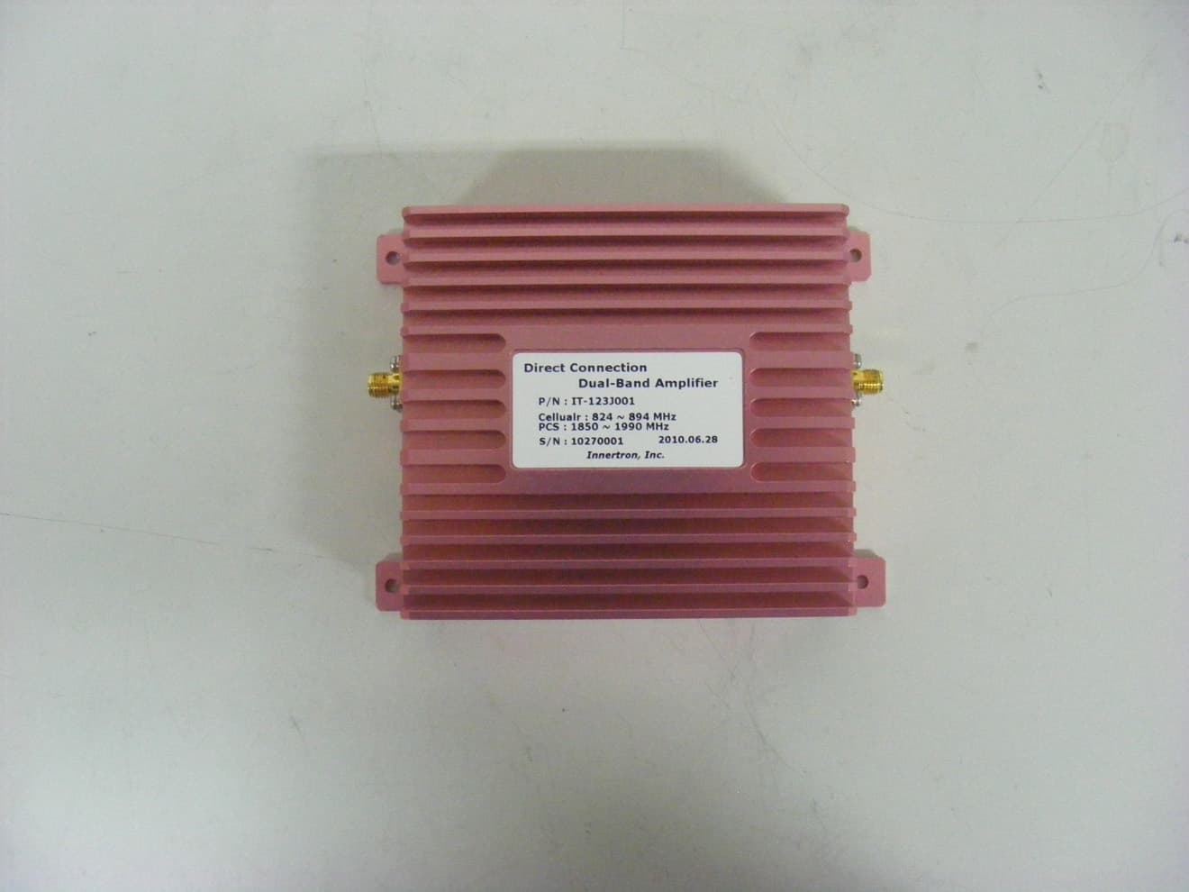
Click to zoom
Application Details
- Equipment Class
- PCB - PCS Licensed Transmitter
- Date of Grant
- Feb 15, 2011
- Application Purpose
- Original Equipment
- Date of Application
- Feb 08, 2011
- Equipment Note
- Dual Band Booster
- Frequency Range
- 1931.30000000 - 1988.80000000
- Company
- INNERTRON, INC
- Country
- South Korea
Documents & Files
Document Text
Text extracted from the exhibit documents filed with the FCC. Open a document above to read the original.
Users Manual
Direct Connection Dual-Band Amplifier/Booster Installation and Operation manual Innertron, Inc. www.Innertron.com Best Call Direct Connection Dual-Band Amplifier / Booster Installation and Operation Manual Innertron, Inc. 96B 5L 663-4 Gojan-dong, Namdong-gu, Incheon-city 405-310 Korea Phone : +82-32-816-1456 / 1458 Fax : +82-32-816-1457 Mobile : +82-10-6602-6980 Website: www.innertron.com Email: [email protected] Direct Connection Dual-Band Amplifier / Booster Installation and Operation Manual Congratulations on the purchase of our Best Call Cellular/PCS Booster! How it Works Best Call Direct Connection Dual-Band Amplifier / Booster has been developed to enhance the performance of cell phone in vehicle. Its advanced technology is designed to significantly improve voice and reduce disconnects and drop-outs. The amplifier works with one antenna : communicates with the cell site and one cable : connected to cell-phone. The antenna will collect the outside signal and send it through a cable to the booster. The signal is then boosted and sent through a cable to a cell-phone. Direct Connection Dual-Band Amplifier/Booster Kit Contents 1. Direct Connection Amplifier/Booster Unit 2. Magnet Dual-Band Monopole Antenna Unit 3. Cable 4. DC Plug-in Power Supply 5. Cable Wrench Installing your Best Call Booster 1. Antenna must be mounted a minimum distance of 50 cm (1.64ft) away from any person(s). 2. You may place your amplifier anywhere inside your vehicle (except as mentioned above). 3. The amplifier’s location should be easily accessible and mounted away from moving parts, excessive heat or moisture. 4. The exterior antenna must be mounted outside the vehicle and at a distance that can be reached from the supplied antenna cable. Direct Connection Dual-Band Amplifier/Booster Installation and Operation manual Innertron, Inc. www.Innertron.com Installation Cautions 1. Use caution to avoid drilling through or near fuel lines or fuel tanks; brake lines; or electrical wiring. 2. Do not mount the amplifier or its associated wiring in a location that may interfere with the safe operation of the vehicle. Caution: Connection to the negative side with the positive lead will cause damage to the amplifier. Installation of In-Vehicle To meet the FCC Exposure Guidelines, the antenna should be installed so there is at least 20 cm of separation between the body of the user or nearby persons and the antenna. NO.ParameterSpecification FrequencyCellular : 824~849MHz 1 Gain10dB norminal 2 Channel Power 12dBm 3 Flatness4dB 4 Moudlation CDMA Only FrequencyCellular : 869~894MHz 5 Gain10dB norminal *Downlink RF Power:-5dBm 6 N.F.4dB norminal 7 Flatness4dB 8 Moudlation CDMA Only FrequencyPCS : 1850~1910MHz 9 Gain10dB norminal 10 Channel Power 12dBm 11 Flatness6.5dB 12 Moudlation CDMA Only FrequencyPCS : 1930~1990MHz 13 Gain10dB norminal*Downlink RF Power:-5dBm 14 N.F.4dB norminal 15 Flatness6.5dB 16 Moudlation CDMA Only 17 Power Requirements 9V/600mA (Norminal) , 9V/2A (Max) 18 ConnectorsSMA 19 Dimensions91x100x32 20 Weight0.50 kg Direct Connection Dual-Band Amplifier/Booster Technical Specifications Notice Trademark R-tron is a registered trademark of R-tron Inc. Other products and company names mentioned here in this manual might be trademarks or trade names of their respective owners. Copyright Copyright © R-tron Inc. 2000-2010 All Rights Reserved Any reproduction, distribution, or revisions of any or all portions of this manual is prohibited without written permission from R-tron Inc. Notice This document describes the specifications, installation, and operation of the OTA repeater. Hardware and software mentioned in this document are subject to continuous development and improvement. Consequently, there may be minor discrepancies between the information in the document, performance, and design of the product. Specifications, dimensions, and other statements mentioned in this document are subject to change without notice. Questions or Comments Address: R-tron America Inc. 6402 College Boulevard, Overland Park, KS 66211 Phone: +1-913-344-9977, 1-888-31R-TRON Fax: +1-913-344-9988 E-mail: [email protected] Website: www.rtronamerica.com FCC Part 15.19 This device complies with part 15 of the FCC Rules. Operation is subject to The following two conditions: (1) This device may not cause harmful interference, and (2) this device must accept any interference received, including interference that may cause undesired operation. FCC Part 15.21 Any changes or modifications (including the antennas) made to this device that are not expressly approved by the manufacturer may void the user's authority to operate the equipment. RF Exposure Statement FCC RF Radiation Exposure Statement: This equipment complies with FCC RF Radiation exposure limits set forth for an uncontrolled environment. This device and its antenna must not be co-located or operating in conjunction with any other antenna or transmitter.
Attestation Statements
INNERTRON, INC 96 Block 5Lot 663-4 Gojandong, Namdong-gu, Incheon City, South Korea Date: November 16, 2010 Federal Communications Commission 7435 Oakland Mills Road Columbia MD 21046 c.c. UL Compliance Certification Services Certification Division 47173 Benicia Street Fremont, CA 94538, USA To whom it may concern: I, the undersigned, hereby authorize Lab Manager Jim. Kim and of SGS Testing Korea Co., Ltd and hereafter referred to as SGS Testing Korea, to act on our behalf in all manners relating to application for equipment authorization, including signing of all documents relating to these matters. Any and all acts carried out by Lab Manager Jim. Kim of SGS Testing Korea Co., Ltd on our behalf shall have the same effect as acts of our own. I, the undersigned, hereby certify that we are not subject to a denial of federal benefits, that includes FCC benefits, pursuant to Section 5301 of the Anti-Drug Abuse Act of 1988, 21 U.S.C. 853(a). In authorizing SGS Testing Korea as our agent, we still recognize that we are responsible to: a) comply with the relevant provisions of the certification program; b) make all necessary arrangements for the conduct of the evaluation, including provision for examining documentation and access to all areas, records (including internal audit reports) and personnel for the purposes of evaluation (e.g. testing, inspection, assessment, surveillance, reassessment) and resolution of complaints; c) make claims regarding certification only in respect of the scope for which certification has been granted; d) do not use our product certification in such a manner as to bring the Certification Division into disrepute and not make any statement regarding our product certification which the Certification Division may consider misleading or unauthorized; e) upon suspension or cancellation of certification, discontinue use of all advertising matter that contains any reference thereto and return any certification documents as required by the Certification Division; INNERTRON, INC 96 Block 5Lot 663-4 Gojandong, Namdong-gu, Incheon City, South Korea f) use certification only to indicate the products are certified as being in conformity with specified standards; g) endeavor to ensure that no certificate or report nor any part thereof is used in a misleading manner; h) ensure that any reference to our product certification in communication media such as documents, brochures or advertising, complies with the requirements of the Certification Division; i) keep a record of all complaints made known to the us relating to the product’s compliance with requirements of the relevant standard and to make these records available to the Certification Division when requested; j) take appropriate action with respect to such complaints and any deficiencies found in products or services that affect compliance with the requirements for certification; k) document the actions taken. This authorization is valid until further written notice from the applicant. Sincerely Yours, Jong Woo Ha / Manager INNERTRON, INC
Cover Letter(s)
INNERTRON, INC 96 Block 5Lot 663-4 Gojandong, Namdong-gu, Incheon City, South Korea Federal Communications Commission 7435 Oakland Mills Road Columbia, MD 21046 Gentlemen: This letter is to comply with Section 0.457(d)(2)(i) and 0.459 pertaining to confidential material. We, INNERTRON, INC., would like the following documents regarding this submission for FCC ID: YP3-IT-132J001 to be kept confidential. 1. Schematics 2. Operating description 3. Block Diagram 4. Tune-up Procedure 5. Parts List The above material contains trade secrets or technical data, which would customarily be guarded from competitors. We do not want these documents to be accessible to the general public. Sincerely, Jong Woo Ha / Manager INNERTRON, INC
External Photos
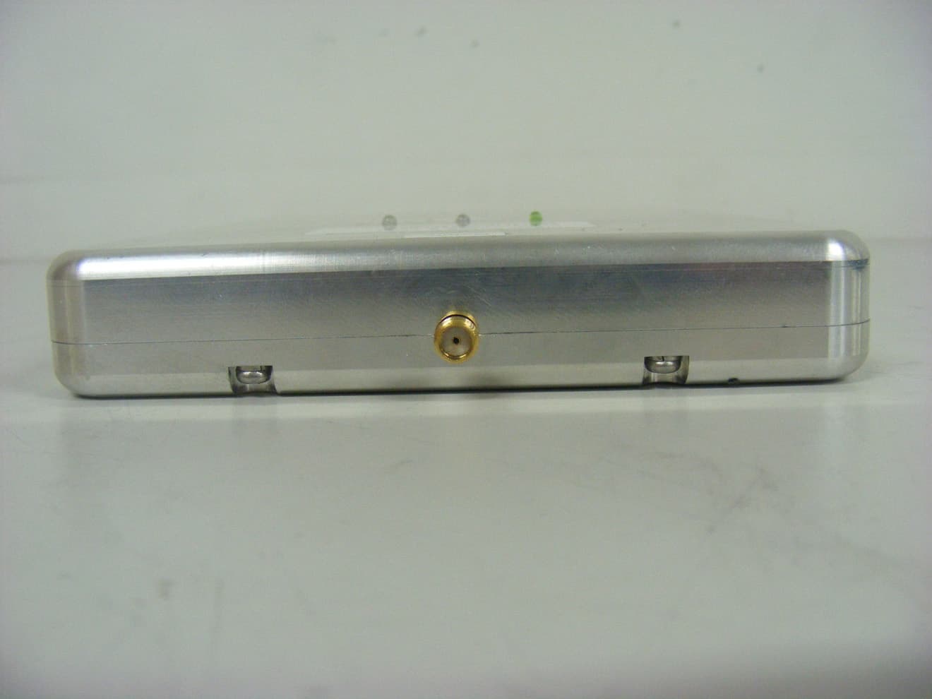
External photos of EUT Front view of EUT Rear view of EUT Side view of EUT Top view of EUT Bottom view of EUT
ID Label/Location Info
FCC Label (Dual Band Booster) 1. FCC Label Drawing 2. FCC Label location INNERTRON, INC Model : Dual Band Booster FCC ID : YP3-IT-132J001 Made in Korea
Internal Photos
Internal photos of EUT Inner view of Main PCB Top view of Main PCB Bottom view of Main PCB
Test Report
Report Number: F690501/RF-RTL004287-1 Page: 2 of 59 The results shown in this test report refer only to the sample(s) tested unless otherwise stated. This test report cannot be reproduced, except in full, without prior written permission of the Company. SGS Testing Korea Co., Ltd. 18-34, Sanbon-dong, Gunpo-si, Gyeonggi-do, Korea, 435-040 Tel. +82 31 428 5700 / Fax. +82 31 427 2371 www.electrolab.kr.sgs.com INDEX TABLE OF CONTENTS Page 1. General Information ---------------------------------------------------------------------------------------3 2. RF Output Power ------------------------------------------------------------------------------------------6 3. Occupied Bandwidth 26 ---------------------------------------------------------------------------- 16 4. Spurious Emissions At Antenna Terminal -----------------------------------------------------------24 5. Band Edge --------------------------------------------------------------------------------------------------37 6. Field Strength of Spurious Radiation -----------------------------------------------------------------46 7. Frequency Stability --------------------------------------------------------------------------------------- 53 8. RF Exposure Evaluation -------------------------------------------------------------------------------- 58 Report Number: F690501/RF-RTL004287-1 Page: 3 of 59 The results shown in this test report refer only to the sample(s) tested unless otherwise stated. This test report cannot be reproduced, except in full, without prior written permission of the Company. SGS Testing Korea Co., Ltd. 18-34, Sanbon-dong, Gunpo-si, Gyeonggi-do, Korea, 435-040 Tel. +82 31 428 5700 / Fax. +82 31 427 2371 www.electrolab.kr.sgs.com 1. General information 1.7. Testing laboratory SGS Testing Korea Co., Ltd. - 705, Dongchun-Dong Sooji-Gu, Yongin-Shi, Kyungki-Do, South Korea. - Wireless Div. 2FL, 18-34, Sanbon-dong, Gunpo-si, Gyeonggi-do, Korea 435-040 www.electrolab.kr.sgs.com Telephone : +82 +31 428 5700 FAX : +82 +31 427 2371 1.2. Details of applicant Applicant :INNERTRON, INC Address :96 Block 5 Lot 663 Gojan-dong, Namdong-gu, Incheon-City 405-310, Korea Contact Person : Jong U , Ha Phone No. : 82 +31 816 1456 1.3. Description of EUT Kind of Product Booster Model Name Dual Band Booster Serial Number 10270001 Power Supply DC 12 V Rated Power 13 dBm(Uplink), -5 dBm(Downlink) Frequency Range 824 ~ 849 (Uplink), 869 ~ 894 (Downlink) 1 850 ~ 1 910 (Uplink), 1 930 ~ 1 990 (Downlink) Antenna Gain 2.12 dBi( 806 – 894 ) , 3.12 dBi (1 850 – 1 990 ) Report Number: F690501/RF-RTL004287-1 Page: 4 of 59 The results shown in this test report refer only to the sample(s) tested unless otherwise stated. This test report cannot be reproduced, except in full, without prior written permission of the Company. SGS Testing Korea Co., Ltd. 18-34, Sanbon-dong, Gunpo-si, Gyeonggi-do, Korea, 435-040 Tel. +82 31 428 5700 / Fax. +82 31 427 2371 www.electrolab.kr.sgs.com 1.5. Test equipment list Equipment Manufacturer Model Cal Due. Signal Generator Agilent E4438C Mar. 31, 2011 Spectrum Analyzer Agilent E4440A Mar. 31, 2011 Attenuator Agilent 8498A Apr. 01, 2011 High Pass Filter Wainwright WHK3.0/18G-10SS Sep. 29, 2011 Band Reject Filter Wainwright WRCG824/849-814/85 960/10SS Apr. 01, 2011 DC power Supply Agilent U8002A Jan. 06, 2011 Preamplifier H.P. 8447F Jun. 05, 2011 Test Receiver R & S ESU26 Apr. 15, 2011 Bilog Antenna SCHWARZBECK MESSELEKTRONIK VULB9163 Jun. 22, 2011 Horn Antenna Rohde & Schwarz HF 906 Oct. 08, 2011 Horn Antenna SCHWARZBECK BBH 9120D Nov. 09, 2011 Dipole Antenna VHAP/UHAP 975/958 Oct. 10, 2011 Antenna Master EMCO 1050 N.C.R. Turn Table Daeil EMC DI-1500 N.C.R. Anechoic Chamber SY Corporation L × W × H (9.6 m × 6.4 m × 6.6 m) Jan. 27, 2011 Report Number: F690501/RF-RTL004287-1 Page: 5 of 59 The results shown in this test report refer only to the sample(s) tested unless otherwise stated. This test report cannot be reproduced, except in full, without prior written permission of the Company. SGS Testing Korea Co., Ltd. 18-34, Sanbon-dong, Gunpo-si, Gyeonggi-do, Korea, 435-040 Tel. +82 31 428 5700 / Fax. +82 31 427 2371 www.electrolab.kr.sgs.com 1.6. Summary of test results The EUT has been tested according to the following specifications: APPLIED STANDARD : FCC Part 22,24 Section in FCC part Test Item Result §2.1053 §22.917(e) §24.238(a) Spurious Radiated Emission Complied §2.1046(a) Conducted Output Power Complied §2.1049(h) (i) Occupied Bandwidth Complied §2.1051 §22.917(e) §24.238(a) Spurious Emission at Antenna Terminal Complied §2.1055 §22.355 §24.235 Frequency Stability Complied §22.917(e) §24.238(a) Band Edge Complied §1.1307(b)(1) Maximum Permissible Exposure (Exposure of Humans to RF Fields) Complied 1.7. Test report revision Revision Report number Description 0 F690501/RF-RTL004287 Initial 1 F690501/RF-RTL004287-1 Additional test Report Number: F690501/RF-RTL004287-1 Page: 6 of 59 The results shown in this test report refer only to the sample(s) tested unless otherwise stated. This test report cannot be reproduced, except in full, without prior written permission of the Company. SGS Testing Korea Co., Ltd. 18-34, Sanbon-dong, Gunpo-si, Gyeonggi-do, Korea, 435-040 Tel. +82 31 428 5700 / Fax. +82 31 427 2371 www.electrolab.kr.sgs.com 2. RF Output Power 2.1. Limit Requirements: CFR 47, Section §2.1046 2.2. Test Procedure 1. The transmitter was tested while in a continuous transmit mode. 2. The EUT was tuned to a low, middle, and high channel in both the downlink (base to mobile) and uplink (mobile to base) directions. 3. RF power output was measured with an RF input level at the point just before the compression point of the amplifier. 4. This is the point of maximum RF output power. If the RF input level is increased beyond this point, the amplifier gain (and consequently output power) is automatically reduced. Spectrum Analyzer Signal Generator Attenuator EUT Report Number: F690501/RF-RTL004287-1 Page: 7 of 59 The results sh…
Text truncated - open the document above for the full version.
Test Setup Photos
Test setup photo of EUT A. Photos of Spurious Emission Test
Contact Information
Applicant
Jong Woo Ha(Section Chief)
Test Firm
SGS Korea Co., Ltd.Forest Lee
Technical Specifications
| # | Rule Parts | Frequency Range | Power Output | Emission | Tolerance |
|---|---|---|---|---|---|
| 4 | 24E | 1.93 GHz - 1.99 GHz | 3.80 mW | F9W | Amp |
Other Applications from INNERTRON, INC
YP3-IT-109J001
Dec 21, 2010Dual Band Repeater
Equipment Class
PCB - PCS Licensed Transmitter