YP9AT1595IsatDOCK
Beam Communications Pty Ltd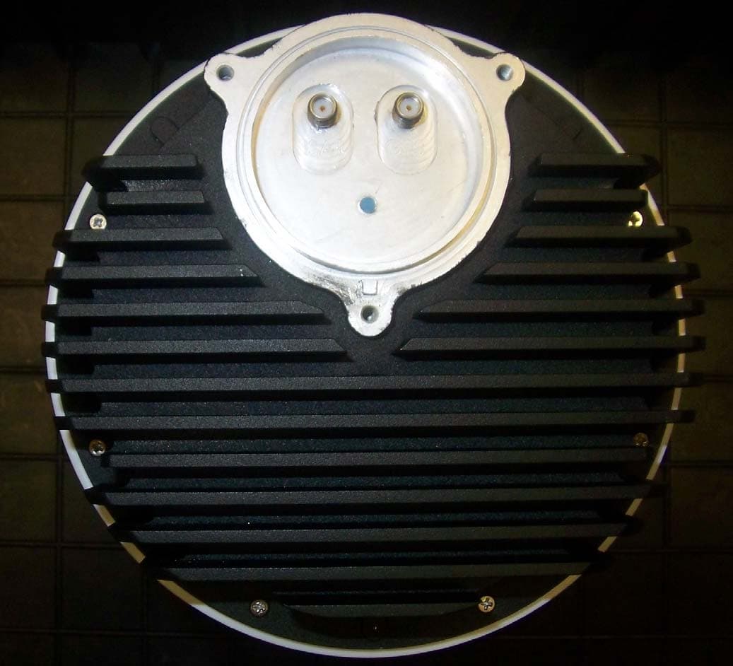
Click to zoom
Application Details
- Equipment Class
- AMP - Amplifier
- Date of Grant
- Oct 14, 2010
- Application Purpose
- Original Equipment
- Date of Application
- Oct 14, 2010
- Equipment Note
- IsatDOCK
- Frequency Range
- 1626.50000000 - 1660.50000000
- Company
- Beam Communications Pty Ltd
- Country
- Australia
Documents & Files
Document Text
Text extracted from the exhibit documents filed with the FCC. Open a document above to read the original.
Users Manual
BETA – IsatDock Drive/Lite Overview Beam Communications STRICTLY CONFIDENTIAL Page 1 of 25 Filename:IsatDock Docking Station _Beta _Drive_Lite_v3.docx IsatDock Docking Station BETA USER GUIDE DRIVE & LITE DOCUMENT STATUS Filename: IsatDock Docking Station _Beta _Drive_Lite_v1_1.docx Client: Inmarsat Status: Commercial In-Confidence (release status: see Revision History) Author: William Christie Authorised by: Comment Closure Date: REVISION HISTORY Version Date Changes 01 30-AUG-2010 Initial Draft Release BETA – IsatDock Drive/Lite Overview Beam Communications STRICTLY CONFIDENTIAL Page 2 of 25 Filename:IsatDock Docking Station _Beta _Drive_Lite_v3.docx TABLE OF CONTENTS 1. Overview....................................................... 4 1.1. LITE/DRIVE – Key Features ................. 5 2. Antenna connection ...................................... 6 3. Functionality ................................................. 7 3.1. Docking Procedure ................................ 7 3.2. DRIVE – Panel Interfaces ..................... 9 3.3. Additional Buttons and LED’s ................ 9 3.4. Adjusting LED Brightness .................... 11 3.5. Keylock ................................................ 11 4. Installation .................................................. 12 4.1. Privacy Handset .................................. 12 4.2. Mounting the privacy handset bracket to the IsatDock ................................................... 13 4.3. LITE/DRIVE – RAM Mount .................. 15 5. Electrical Interfaces .................................... 16 5.1. DRIVE – Main Loom ............................ 16 5.2. Powering from the “DC power cable / lead” 17 6. Physical Dimensions .................................. 18 6.1. LITE/DRIVE ......................................... 18 6.2. Privacy Handset .................................. 20 7. Placing a call – Inbuilt speakerphone (Drive) and Privacy handset (Lite & Drive) .................... 21 8. Adjusting Volume ........................................ 21 9. Configuring the Unit .................................... 22 BETA – IsatDock Drive/Lite Overview Beam Communications STRICTLY CONFIDENTIAL Page 3 of 25 TABLE OF CONTENTS Figure 1 ‐ IsatDock LITE/DRIVE _______________________________________________________________________ 5 Figure 2 – Door Openings ___________________________________________________________________________ 7 Figure 3 – Phone alignment _________________________________________________________________________ 7 Figure 4 – Panel Mounted Electrical Interfaces __________________________________________________________ 9 Figure 5 – Keylock position _________________________________________________________________________ 11 Figure 6 – Privacy Handset mounting cup _____________________________________________________________ 12 Figure 7 – Privacy Handset connection point ___________________________________________________________ 14 Figure 8 – IsatDock DRIVE main loom ________________________________________________________________ 16 BETA – IsatDock Drive/Lite Overview Beam Communications STRICTLY CONFIDENTIAL Page 4 of 25 1. Overview There are four main variants of the IsatDOCK docking stations: 1. IsatDock LITE The IsatDock LITE docking station provides a high quality mechanism for docking the Inmarst IsatPhone Pro handset. The dock is targeted for an in-vehicle application that connects to an external vehicle-mount antenna The IsatDock LITE allows the option of using an optional privacy mode handset mounted alongside the unit. 2. IsatDock DRIVE The dock is design specifically for an in-vehicle handsfree application, connecting to an external vehicle-mount antenna The IsatDock DRIVE allows for the use of an optional privacy mode handset mounted alongside the unit or an external speaker and microphone. The IsatDock DRIVE incorporates inbuilt GPS tracking and the following additional external interfaces: an alert loop, radio muting, and horn alerts. 3. IsatDock PRO The IsatDock PRO allows the flexibility of using a privacy mode handset mounted to the unit or an RJ11/POTS handset connected directly to the rear. The user is also able to operate in a hands free mode with a microphone and speaker combination build into the dock. The installation options of the IsatDock PRO enable the user to mount the IsatDock PRO in either a vertical or horizontal position. 4. IsatDock MARINE The IsatDock MARINE docking station allows the flexibility of using a privacy mode handset mounted to the unit or an RJ11/POTS handset connected directly to the unit. The terminal itself is designed with IP rating for use in harsh environments. The IsatDock DRIVE incorporates inbuilt GPS tracking and an alert loop function. BETA – IsatDock Drive/Lite Overview Beam Communications STRICTLY CONFIDENTIAL Page 5 of 25 1.1. LITE/DRIVE – Key Features Figure 1 - IsatDock LITE/DRIVE R R A A M M M M O O U U N N T T I I S S A A T T P P H H O O N N E E P P R R O O R R E E L L E E A A S S E E B B U U T T T T O O N N S S T T A A T T U U S S I I N N D D I I C C T T I I O O N N I I S S A A T T P P H H O O N N E E P P R R O O A A D D D D I I T T I I O O N N A A L L B B U U T T T T O O N N S S BETA – IsatDock Drive/Lite Overview Beam Communications STRICTLY CONFIDENTIAL Page 6 of 25 2. Antenna connection SMA SMA TNC SMA Satellite Antenna Cable GPS Antenna Cable BETA – IsatDock Drive/Lite Overview Beam Communications STRICTLY CONFIDENTIAL Page 7 of 25 3. Functionality 3.1. Docking Procedure The following docking procedure is common across each of the docking station types PREPARATION: To place the IsatPro Phone into the docking unit, both the ‘doors’ on the external antenna connectors and the USB/Audio connectors need to opened. The antenna ‘door’ must be placed at 90 degrees to the antenna connector cavity and run parallel to the top edge of the phone The ‘door’ in the base of the phone should be in the fully opened position. Figure 2 – Door Openings DOCKING: To dock the handset, al…
Text truncated - open the document above for the full version.
Users Manual
BETA – IsatDock Overview Beam Communications STRICTLY CONFIDENTIAL Page 1 of 29 Filename:IsatDock Docking Station _Beta _Marine_v3.docx IsatDock Docking Station BETA USER GUIDE PRO & MARINE DOCUMENT STATUS Filename: IsatDock Docking Station _Beta _Marine_v1.docx Client: Inmarsat Status: Commercial In-Confidence (release status: see Revision History) Author: William Christie Authorised by: Comment Closure Date: REVISION HISTORY Version Date Changes 01 30-AUG-2010 Initial Draft Release BETA – IsatDock Overview Beam Communications STRICTLY CONFIDENTIAL Page 2 of 29 Filename:IsatDock Docking Station _Beta _Marine_v3.docx TABLE OF CONTENTS 1. Overview....................................................... 4 1.1. PRO/MARINE – Key Features .............. 5 2. Antenna connection ...................................... 6 3. Functionality ................................................. 7 3.1. Docking Procedure ................................ 7 3.2. PRO/MARINE Privacy Handset ............ 8 3.3. PRO/MARINE - Access to Rear Connector Bay ................................................. 8 3.4. PRO/MARINE Security Bolts ................. 9 3.5. Additional Buttons and LED’s .............. 11 3.6. Adjusting LED Brightness .................... 12 3.7. Keylock ................................................ 12 3.8. MARINE - Cover .................................. 13 4. Installation .................................................. 14 4.1. PRO/MARINE – Cable routing ............ 14 4.3. PRO/MARINE – Privacy Handset ....... 15 4.4. PRO/MARINE Mounting Orientations . 17 4.5. PRO/MARINE – Mounting Bracket ...... 18 5. Electrical Interfaces .................................... 19 5.1. PRO/MARINE - Antenna Connectors .. 19 5.2. PRO/MARINE – Rear Connector Bay . 19 5.3. Powering from the “DC power cable / lead” 20 6. Physical Dimensions .................................. 21 6.1. PRO/MARINE ...................................... 21 6.2. Privacy Handset .................................. 22 6.3. Wall Bracket ........................................ 23 7. Placing a call – Inbuilt speakerphone and Privacy handset ................................................. 24 8. Placing a call – POTS/RJ11 Interface ........ 24 9. Adjusting Volume ........................................ 24 10. Configuring the Unit ................................ 26 11. Antenna Specifications ........................... 27 11.1. FCC Information .............................. 29 BETA – IsatDock Overview Beam Communications STRICTLY CONFIDENTIAL Page 3 of 29 TABLE OF CONTENTS Figure 1 ‐ IsatDock PRO/MARINE _____________________________________________________________________ 5 Figure 2 – Door Openings ___________________________________________________________________________ 7 Figure 3 – Phone alignment _________________________________________________________________________ 7 Figure 4 – Privacy Handset – ‘Off Hook’________________________________________________________________ 8 Figure 5 – Privacy Handset – mounting points __________________________________________________________ 8 Figure 13 – PRO/MARINE rear cover panel _____________________________________________________________ 9 Figure 8 – Security Bolts ___________________________________________________________________________ 10 Figure 9 – Mounting Bracket security ________________________________________________________________ 10 Figure 10 – Keylock position ________________________________________________________________________ 12 Figure 11 – IsatDock MARINE cover __________________________________________________________________ 13 Figure 12 – Cover Seal ____________________________________________________________________________ 13 Figure 14 – PRO/MARINE cable routing options ________________________________________________________ 14 Figure 16 – Mounting Cup options ___________________________________________________________________ 15 Figure 17 – Mounting Cup Clip ______________________________________________________________________ 15 Figure 18 – Mounting Cup (Marine Version) ___________________________________________________________ 16 Figure 19 – Privacy Handset mounting cup ____________________________________________________________ 16 Figure 20 – Privacy Handset connection point __________________________________________________________ 17 Figure 6 – PRO/MARINE mounting Orientations ________________________________________________________ 17 Figure 7 – Fitting the Mounting Bracket ______________________________________________________________ 18 Figure 21 – External Antenna Electrical Interfaces ______________________________________________________ 19 Figure 22 – Connector Bay Electrical Interfaces ________________________________________________________ 19 BETA – IsatDock Overview Beam Communications STRICTLY CONFIDENTIAL Page 4 of 29 1. Overview There are four main variants of the IsatDOCK docking stations: 1. IsatDock LITE The IsatDock LITE docking station provides a high quality mechanism for docking the Inmarst IsatPhone Pro handset. The dock is targeted for an in-vehicle application that connects to an external vehicle-mount antenna The IsatDock LITE allows the option of using an optional privacy mode handset mounted alongside the unit. 2. IsatDock DRIVE The dock is design specifically for an in-vehicle handsfree application, connecting to an external vehicle-mount antenna The IsatDock DRIVE allows for the use of an optional privacy mode handset mounted alongside the unit or an external speaker and microphone. The IsatDock DRIVE incorporates inbuilt GPS tracking and the following additional external interfaces: an alert loop, radio muting, and horn alerts. 3. IsatDock PRO The IsatDock PRO allows the flexibility of using a privacy mode handset mounted to the unit or an RJ11/POTS handset connected directly to the rear. The user is also able to operate in a hands free mode with a microphone and speaker combination build into the dock. The installation optio…
Text truncated - open the document above for the full version.
Cover Letter(s)
Oct. 05, 2010 Federal Communication Commission 7435 Oakland Mills Road Columbia, MD 21046 USA Subject: Certification Application under FCC CFR 47, Parts 2 and 25 (Subpart C) - 1.6 GHz Mobile-Satellite Service Applicant: Beam Communications Pty Ltd Products: IsatDOCK Models: AT1595-82 & AT1595-83 FCC ID: YP9AT1595 Dear Sir/Madam, As appointed agent for Beam Communications Pty Ltd, we would like to submit the application for certification of the above product. Please review all required documents uploaded to your E-Filing web site. Note: Models AT1595-82 and AT1595-83 are exactly identical except for the antenna element types. If you have any queries, please do not hesitate to contact us. Yours truly, DHARMAJIT SOLANKI Dhamajit Solanki Authorized Agent UltraTech Group of Labs FCC TCB & IC CB Ultratech’s Accreditations: 0685 FCC 91038 1309 46390-2049 NvLap Lab Code 200093-0 SL2-IN-E-1119R Korea KCC-RRL CA2049 3000 Bristol Circle, Oakville, Ontario, Canada L6H 6G4 Tel.: (905) 829-1570 Fax.: (905) 829-8050 Website: www.ultratech-labs.com Email: [email protected] Oct. 05, 2010 Beam Communications Pty Ltd 5/8 Anzed Court Mulgrave, Victoria Australia 3170 Attn.: Mr. Greg Incoll Subject: Certification Application under FCC CFR 47, Parts 2 and 25 (Subpart C) - 1.6 GHz Mobile-Satellite Service Product: IsatDOCK Model: AT1595-82 & AT1595-83 FCC ID: YP9AT1595 Dear Mr. Incoll, The product sample has been tested in accordance with FCC CFR 47, Parts 2 and 25 (Subpart C) - 1.6 GHz Mobile-Satellite Service, and the results and observation were recorded in the engineering report, Our File No.: BEAM-014FCC25. Enclosed you will find copy of the engineering report. If you have any queries, please do not hesitate to contact us. Yours truly, DHARMAJIT SOLANKI Dhamajit Solanki Authorized Agent UltraTech Group of Labs FCC TCB & IC CB Ultratech’s Accreditations: 0685 FCC 91038 1309 46390-2049 NvLap Lab Code 200093-0 SL2-IN-E-1119R Korea KCC-RRL CA2049 3000 Bristol Circle, Oakville, Ontario, Canada L6H 6G4 Tel.: (905) 829-1570 Fax.: (905) 829-8050 Website: www.ultratech-labs.com Email: [email protected]
Cover Letter(s)
an AS9100 Certified Company 20732 Lassen Street, Chatsworth, CA 91311 Phone: (818) 993-3842 Fax: (818) 993-4525 Date: 09/22/2010 To Whom It May Concern Subject:Confidentiality Letter Applicant:AeroAntenna Technology, Inc. FCC ID:YP9AT1595 Dear Sir/Madam: AeroAntenna Technology, Inc. would like to request the following documents submitted with this application for certification be withheld from public disclosure as per Section 0.457 & 0.459 of FCC Rules. • Operational Description • Block Diagram • Schematics • Parts List • Tuning Info The above materials contain trade secrets and proprietary information not customarily released to the public. The public disclosure of these materials may be harmful to the applicant and provide unjustified benefits to its competitors. Sincerely, Alex Sissoev Sr. Electrical Engineer Phone: (818) 993-3842 ext 272 Fax: (818) 993-4525 Email: [email protected] AeroAntenna Technology, Inc.
Cover Letter(s)
November 10, 2010 Federal Communication Commission 7435 Oakland Mills Road Columbia, MD 21046 USA Subject: Justification for Supersede of Test Report Exhibit Applicant: Beam Communications Pty Ltd Products: IsatDock Models: AT1595-82 & AT1595-83 FCC ID: YP9AT1595 Grant Date: October 15, 2010 Dear Sir/Madam, As appointed agent for Beam Communications Pty Ltd, we like to request on behalf of the applicant to allow us to supersede our test report exhibit. The test report was updated with exact Product Name & Model Nos. as consistent with marketing literature, corrected some typos and updated EUT specifications. These changes are only cosmetic in nature and there were no changes made to the test data/results of the report. If you have any queries, please do not hesitate to contact us. Sincerely, DHARMAJIT SOLANKI Dharmajit Solanki Authorized Agent UltraTech Group of Labs FCC TCB & IC CB Ultratech’s Accreditations: 0685 FCC 91038 1309 46390-2049 NvLap Lab Code 200093-0 SL2-IN-E-1119R Korea KCC-RRL CA2049 3000 Bristol Circle, Oakville, Ontario, Canada L6H 6G4 Tel.: (905) 829-1570 Fax.: (905) 829-8050 Website: www.ultratech-labs.com Email: [email protected]
External Photos
Annex 2: External Photographs of the Equipment under Tests Beam Communications - IsatDOCK, Model No.: AT1595-82 & AT1595-83 FCC ID: YP9AT1595 IC: 9218A-AT1595 Photo #1: Model AT1595-82 Annex 2: External Photographs of the Equipment under Tests Beam Communications - IsatDOCK, Model No.: AT1595-82 & AT1595-83 FCC ID: YP9AT1595 IC: 9218A-AT1595 Photo #2: Model AT1595-83 Annex 2: External Photographs of the Equipment under Tests Beam Communications - IsatDOCK, Model No.: AT1595-82 & AT1595-83 FCC ID: YP9AT1595 IC: 9218A-AT1595 Photo #3: Model AT1595-82 & AT1595-83
ID Label/Location Info
A B C D DESCRIPTIONREV.DATE REVISIONS APPROVED DRAWN N EXT ASSY SCALE FRACT = 1/32 APPROVED ENGR MFG SIZECAGE CODE REV Q.A. 0UVG2 NONE SHEET 1 OF A DRAWING NO. TITLE DO NOT SCALE THIS DRAWING ALL DIMENSIONS ARE IN INCHES HOLE DIA. DIMENSIONING & TOLERANCING P ER ASME Y14.5M-1994 TOLERANCES: MACHINED PARTS 63 S URFACE ROUGHNESS REMOVE BURRS AND BREAK SHARP EDGES: PART TO BE CLEAN AND OIL FREE DRAWN IN ANG. = 1/2 CHECKED MOLDED PARTS 32 .0135 - .125 .126 - .250 .251 - .500 .501 - .750 +.004 -.001 -.001 +.005 -.001 +.006 -.001 +.008 B C 34 D 12 AeroAntenna Technology Inc TOLERANCE .XXX = .005 .XX = .01 AS9100 CERTIFIED CO. copied, disclosed or used for any purpose other than consideration of document without the express written permission of a duly authorized representative of said AeroAntenna Technology, Inc. PROPRIETARY NOTICE: This document contains proprietary information of AeroAntenna Technology, Inc. (AAT). Neither the document nor said proprietary information shall be published, reproduced, A. GUTIERREZ E. NABOYSHCHIKOV 09/22/10 LABEL AT15958204 1 09/22/10 A T 15958204 1 ENGINEERING RELEASED 09/22/10 CAD I:\CAD\AT1595\-82\AT15958204_1 SHIP AT1595-82 I. SIROTIN 09/22/10 1 2. 1. PART NO.: THT-37-486-10. TEXT TO BE PRINTED BY BRADY PROGRAM. WITH ADHESIVE BACKING. MATERIAL: METALIZED POLYESTER, .002-.003 THICK, NOTES: UNLESS OTHERWISE SPECIFIED (.50) ( 1.50) 4X R.06 SEE SEPARATE PARTS LIST D.O.W: XX/XX S /N: XXXXX AT1595-82 IC: 9218A-AT1595 FCC ID: YP9AT1595 Canada: 310 Chatsworth, CA. U.S.A. AeroAntenna Technology, Inc. BLACK TEXT WHITE AREA WHITE TEXT BLACK AREA APPROVED D OCUMENT ENGINEERING 09-22-2010
ID Label/Location Info
A B C D DESCRIPTIONREV.DATE REVISIONS APPROVED DRAWN N EXT ASSY SCALE FRACT = 1/32 APPROVED ENGR MFG SIZECAGE CODE REV Q.A. 0UVG2 NONE SHEET 1 OF A DRAWING NO. TITLE DO NOT SCALE THIS DRAWING ALL DIMENSIONS ARE IN INCHES HOLE DIA. DIMENSIONING & TOLERANCING P ER ASME Y14.5M-1994 TOLERANCES: MACHINED PARTS 63 S URFACE ROUGHNESS REMOVE BURRS AND BREAK SHARP EDGES: PART TO BE CLEAN AND OIL FREE DRAWN IN ANG. = 1/2 CHECKED MOLDED PARTS 32 .0135 - .125 .126 - .250 .251 - .500 .501 - .750 +.004 -.001 -.001 +.005 -.001 +.006 -.001 +.008 B C 34 D 12 AeroAntenna Technology Inc TOLERANCE .XXX = .005 .XX = .01 AS9100 CERTIFIED CO. copied, disclosed or used for any purpose other than consideration of document without the express written permission of a duly authorized representative of said AeroAntenna Technology, Inc. PROPRIETARY NOTICE: This document contains proprietary information of AeroAntenna Technology, Inc. (AAT). Neither the document nor said proprietary information shall be published, reproduced, A. GUTIERREZ E. NABOYSHCHIKOV 09/22/10 LABEL AT15958304 1 09/22/10 A T 15958304 1 ENGINEERING RELEASED 09/22/10 CAD I:\CAD\AT1595\-83\AT15958304_1 SHIP AT1595-83 I. SIROTIN 09/22/10 1 2. 1. PART NO.: THT-37-486-10. TEXT TO BE PRINTED BY BRADY PROGRAM. WITH ADHESIVE BACKING. MATERIAL: METALIZED POLYESTER, .002-.003 THICK, NOTES: UNLESS OTHERWISE SPECIFIED (.50) ( 1.50) 4X R.06 SEE SEPARATE PARTS LIST D.O.W: XX/XX S /N: XXXXX AT1595-83 IC: 9218A-AT1595 FCC ID: YP9AT1595 Canada: 310 Chatsworth, CA. U.S.A. AeroAntenna Technology, Inc. BLACK AREA WHITE TEXT BLACK TEXT WHITE AREA APPROVED D OCUMENT ENGINEERING 09-22-2010
ID Label/Location Info
A BC D 5 6 7 8 1 2 3 4 D E S CR I P T I ON S Y M D A T E R E V I S I ON S A PPR O V E D DR A W N N E X T A SS Y S C A L E . XX = . 01 . XXX = . 005 F R A C T = 1 / 32 A PPR O V E D E N GR M F G S I Z E C A G E C O D E R E V Q . A . 0 U V G 2 NON E S H EE T 1 O F B DR A W I N G NO . T I T L E D O NO T S C A L E T H I S DR A W I N G A LL D I M E N S I ON S A R E I N I N C H E S HO L E D I A . T O L E R A N C E D CB A D I M E N S I ON I N G & T O L E R A N C I N G P E R A S M E Y 14 . 5 M - 1994 T O L E R A N C E S : M A C H I N E D P A R T S 63 S U R FA C E R OU G HN E SS R E M O V E B U RR S A N D BR E A K S H A RP E DG E S : P A R T T O B E C L E A N A N D O I L F R EE DR A W N I N A N G . = 1 / 2 Ae r o A n t e nna T ec hno l og y I n c C H E CK E D M O L D E D P A R T S 32 . 0135 - . 125 . 126 - . 250 . 251 - . 500 . 501 - . 750 + . 004 - . 001 - . 001 + . 005 - . 001 + . 006 - . 001 + . 008 A S9100 C E R T I F I E D C O . PR O PR I E T A R Y NO T E : T h i s do c u m e n t c on t a i n s i n f o r m a t i on o f Ae r o A n t e nna T ec hno l og y I n c . ( AA T ) . N e i t h e r t h e do c u m e n t no r s a i d p r op r i e t a r y i n f o r m a t i on s ha ll b e pub li s h e d , r e p r odu ce d , c op i e d , d i s c l o s e d o r u s e d f o r an y o t h e r pu r po s e o t h e r t han c on s i d e r a t i on o f do c u m e n t w i t hou t t h e e x p r e ss w r i tt e n p e r m i s i on o f a du l y au t ho r i z e d r e p r e s e n t a t i v e o f s a i d Ae r o A n t e nna T ec hno l og y I n c . A . G U T I E RR E Z E . N A B O Y S H C H I K O V 09 / 23 / 10 I N M A R S A T / GP S R o H S , M A R I N E A N T E NN A A T 1595 - 82 - R 6 09 / 23 / 10 AT1595-82-R 6 E N G I N EE R I N G R E L E A S E 09 / 23 / 10 C A D I : \ C A D \ A T 1595 \ - 82 \ A T 1595 - 82 - R _ 6 I . S I R O T I N 09 / 23 / 10 1 FREQUENCY: 1518.0 to 1525.0 MHz Inmarsat Receive (extended) 1525.0 to 1559.0 MHz Inmarsat Receive (operational) 1575.42 ± 10.25 MHz (GPS L1) 1626.5 to 1660.5 MHz Inmarsat Transmit (operational) 1668.0 to 1675.0 MHz Inmarsat Transmit (extended) POLARIZATION: RIGHT HAND CIRCULAR LIGHTNING PROTECTION: DC GROUNDED IMPEDANCE: 50 Ω AXIAL RATIO: ≤ 4 dB, 0° ≤ θ ≤ 85° (operational band) ≤ 6 dB, 0° ≤ θ ≤ 85° (extended band) CONNECTOR(S): INMARSAT RX/TX = SMAF GPS = SMAF WEIGHT: 1.91 LBS MAX. OPERATING TEMP: -25°C to +55°C DESIGNED TO: INMARSAT RFI 1401 FCC ID: YP9AT1595 IC: 9218A-AT1595 CANADA: 310 THIS DEVICE COMPLIES WITH PART 15 OF THE FCC RULES. OPERATION IS SUBJECT TO THE FOLLOWING TWO CONDITIONS: (1) THIS DEVICE MAY NOT CAUSE HARMFUL INTERFERENCE, AND(2) THIS DEVICE MUST ACCEPT ANY INTERFERENCE RECEIVED, INCLUDING INTERFERENCE THAT MAY CAUSE UNDESIRED OPERATION. S P E C I F I C A T I ON : 1 I N C H P I P E M OUN T I N G T O 3X 1 / 4 - 20 X 1 / 4 S E T S CR E W 8 . 14 ∅ 5 . 61 2 . 55 ∅ 1 . 40 . XXX = . 010 . XX = . 03 L A B E L L O C A T E D A PPR O X I M A T E L Y W H E R E S HO W N . NO T E S : UN L E SS O T H E R W I S E S P E C I F I E D . T O L E R A N C E : 2 . 1 L A B E L 1 A PPR O V E D D O C U M E N T E N G I N EE R I N G 09 - 23 - 2010
ID Label/Location Info
A BC D 5 6 7 8 1 2 3 4 D E S CR I P T I ON S Y M D A T E R E V I S I ON S A PPR O V E D DR A W N N E X T A SS Y S C A L E . XX = . 01 . XXX = . 005 F R A C T = 1 / 32 A PPR O V E D E N GR M F G S I Z E C A G E C O D E R E V Q . A . 0 U V G 2 NON E S H EE T 1 O F B DR A W I N G NO . T I T L E D O NO T S C A L E T H I S DR A W I N G A LL D I M E N S I ON S A R E I N I N C H E S HO L E D I A . T O L E R A N C E D CB A D I M E N S I ON I N G & T O L E R A N C I N G P E R A S M E Y 14 . 5 M - 1994 T O L E R A N C E S : M A C H I N E D P A R T S 63 S U R FA C E R OU G HN E SS R E M O V E B U RR S A N D BR E A K S H A RP E DG E S : P A R T T O B E C L E A N A N D O I L F R EE DR A W N I N A N G . = 1 / 2 Ae r o A n t e nna T ec hno l og y I n c C H E CK E D M O L D E D P A R T S 32 . 0135 - . 125 . 126 - . 250 . 251 - . 500 . 501 - . 750 + . 004 - . 001 - . 001 + . 005 - . 001 + . 006 - . 001 + . 008 A S9100 C E R T I F I E D C O . PR O PR I E T A R Y NO T E : T h i s do c u m e n t c on t a i n s i n f o r m a t i on o f Ae r o A n t e nna T ec hno l og y I n c . ( AA T ) . N e i t h e r t h e do c u m e n t no r s a i d p r op r i e t a r y i n f o r m a t i on s ha ll b e pub li s h e d , r e p r odu ce d , c op i e d , d i s c l o s e d o r u s e d f o r an y o t h e r pu r po s e o t h e r t han c on s i d e r a t i on o f do c u m e n t w i t hou t t h e e x p r e ss w r i tt e n p e r m i s i on o f a du l y au t ho r i z e d r e p r e s e n t a t i v e o f s a i d Ae r o A n t e nna T ec hno l og y I n c . A . G U T I E RR E Z E . N A B O Y S H C H I K O V 09 / 23 / 10 I N M A R S A T / GP S R o H S , V E H I C U L A R A N T E NN A A T 1595 - 83 - R 2 09 / 23 / 10 AT1595-83-R 2 E N G I N EE R I N G R E L E A S E 09 / 23 / 10 C A D I : \ C A D \ A T 1595 \ - 83 \ A T 1595 - 83 - R _ 2 I . S I R O T I N 09 / 23 / 10 1 FREQUENCY: 1518.0 to 1525.0 MHz Inmarsat Receive (extended) 1525.0 to 1559.0 MHz Inmarsat Receive (operational) 1575.42 ± 10.25 MHz (GPS L1) 1626.5 to 1660.5 MHz Inmarsat Transmit (operational) 1668.0 to 1675.0 MHz Inmarsat Transmit (extended) POLARIZATION: RIGHT HAND CIRCULAR LIGHTNING PROTECTION: DC GROUNDED IMPEDANCE: 50 Ω CONNECTOR(S): INMARSAT RX/TX = SMAF GPS = SMAF WEIGHT: 1.91 LBS MAX. OPERATING TEMP: -25°C to +55°C DESIGNED TO: INMARSAT RFI 1401 FCC ID: YP9AT1595 IC: 9218A-AT1595 CANADA: 310 THIS DEVICE COMPLIES WITH PART 15 OF THE FCC RULES. OPERATION IS SUBJECT TO THE FOLLOWING TWO CONDITIONS: (1) THIS DEVICE MAY NOT CAUSE HARMFUL INTERFERENCE, AND(2) THIS DEVICE MUST ACCEPT ANY INTERFERENCE RECEIVED, INCLUDING INTERFERENCE THAT MAY CAUSE UNDESIRED OPERATION. S P E C I F I C A T I ON : ∅ 5 . 75 3 . 48 M A G N E T M OUN T 8X M OUN T I N G M A G N E T ∅ 5 . 75 R F C A B L E 2X 2 . 85 2 . 85 2X R F C A B L E A N T E NN A A N T E NN A F I X E D M OUN T R E F . I N S T A LL A T I ON HO L E 1 . 64 1 2 . T O L E R A N C E : NO T E S : UN L E SS O T H E R W I S E S P E C I F I E D . L A B E L L O C A T E D A PPR O X I M A T E L Y W H E R E S HO W N . . XX = . 03 . XXX = . 010 1 L A B E L L A B E L 1 A PPR O V E D D O C U M E N T E N G I N EE R I N G 09 - 23 - 2010
Internal Photos
Annex 3: Internal hotographs of the Equipment under Tests Beam Communications - IsatDOCK, Model No.: AT1595-82 & AT1595-83 FCC ID: YP9AT1595 IC: 9218A-AT1595 Photo #1 Annex 3: Internal hotographs of the Equipment under Tests Beam Communications - IsatDOCK, Model No.: AT1595-82 & AT1595-83 FCC ID: YP9AT1595 IC: 9218A-AT1595 Photo #2
RF Exposure Info
ISatDock DRIVE - Installation & User Manual 33 WARNING : To satisfy FCC RF exposure requirements for mobile transmitting devices, a separation distance of 55 cm or more should be maintained between the antenna of this device and persons during device operation. To ensure compliance, operations at closer than this distance is not recommended. The antenna used for this transmitter must not be co-located in conjunction with any other antenna or transmitter WARNING : Changes or modifications not expressly approved by Beam Communications could void the user’s authority to operate the equipment “This device has been designed to operate with the antennas recommended in this manual, and having a maximum gain of 6 dBi dB. Antennas having a gain greater than 6 dBi dB are strictly prohibited for use with this device.” “To reduce potential radio interference to other users, the antenna type and its gain should be so chosen that the equivalent isotropically radiated power (EIRP) is not more than that required for successful communication” FCC PARTS 2 & 25, SUBPART C – 1.6 GHz Mobile-Satellite Service Page 17 IsatDoc, Model No.: AT1595-82 & AT1595-83 FCC ID: YP9AT1595 ULTRATECH GROUP OF LABS File #: BEAM-014FCC25 3000 Bristol Circle, Oakville, Ontario, Canada L6H 6G4 September 17, 2010 Tel. #: 905-829-1570, Fax. #: 905-829-8050, Email: [email protected] , Website: http://www.ultratech-labs.com All test results contained in this engineering test report are traceable to National Institute of Standards and Technology (NIST) 5.2. RF EXPOSURE REQUIRMENTS [§1.1310 & 2.1091] The criteria listed in the following table shall be used to evaluate the environmental impact of human exposure to radio- frequency (RF) radiation. FCC 47 CFR § 1.1310: 5.2.1. Method of Measurements Refer to Sections 1.1310, 2.1091 In order to demonstrate compliance with MPE requirements (see Section 2.1091), the following information is typically needed: (1) Calculation that estimates the minimum separation distance (20 cm or more) between an antenna and persons required to satisfy power density limits defined for free space. (2) Antenna installation and device operating instructions for installers (professional/unskilled users), and the parties responsible for ensuring compliance with the RF exposure requirement (3) Any caution statements and/or warning labels that are necessary in order to comply with the exposure limits (4) Any other RF exposure related issues that may affect MPE compliance FCC PARTS 2 & 25, SUBPART C – 1.6 GHz Mobile-Satellite Service Page 18 IsatDoc, Model No.: AT1595-82 & AT1595-83 FCC ID: YP9AT1595 ULTRATECH GROUP OF LABS File #: BEAM-014FCC25 3000 Bristol Circle, Oakville, Ontario, Canada L6H 6G4 September 17, 2010 Tel. #: 905-829-1570, Fax. #: 905-829-8050, Email: [email protected] , Website: http://www.ultratech-labs.com All test results contained in this engineering test report are traceable to National Institute of Standards and Technology (NIST) Calculation Method of RF Safety Distance: S = PG/4r 2 =EIRP/4r 2 Where: P: power input to the antenna in mW EIRP: Equivalent (effective) isotropic radiated power S: power density mW/cm 2 G: numeric gain of antenna relative to isotropic radiator r: distance to centre of radiation in cm r = EIRP/4S 5.2.2. RF Evaluation Evaluation of RF Exposure Compliance Requirements RF Exp…
Text truncated - open the document above for the full version.
Contact Information
Applicant
G Incoll(Mr)
Technical Contact
UltraTech Engineering Labs Inc.Dharmajit Solanki
[email protected]905-829-1570
3000 Bristol Circle · Oakville, ON · Canada
Non-Technical Contact
AeroAntenna Technology, Inc .Alex Sissoev
[email protected](818) 993-3842
Test Firm
UltraTech Engineering Labs Inc.Tri Luu
Technical Specifications
| # | Rule Parts | Frequency Range | Power Output | Emission |
|---|---|---|---|---|
| 1 | 25 | 1.63 GHz - 1.66 GHz | 5.6 W | G7W |
Other Applications from Beam Communications Pty Ltd
YP9INM800PHONE
Dec 13, 2012Immarsat Phone
Equipment Class
DSS - Part 15 Spread Spectrum Transmitter