Text extracted from the exhibit documents filed with the FCC. Open a document above to read the original.
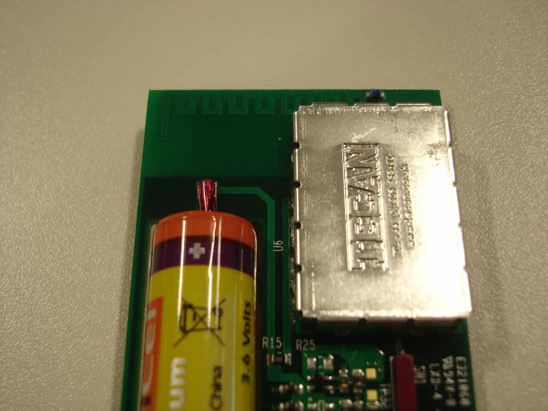
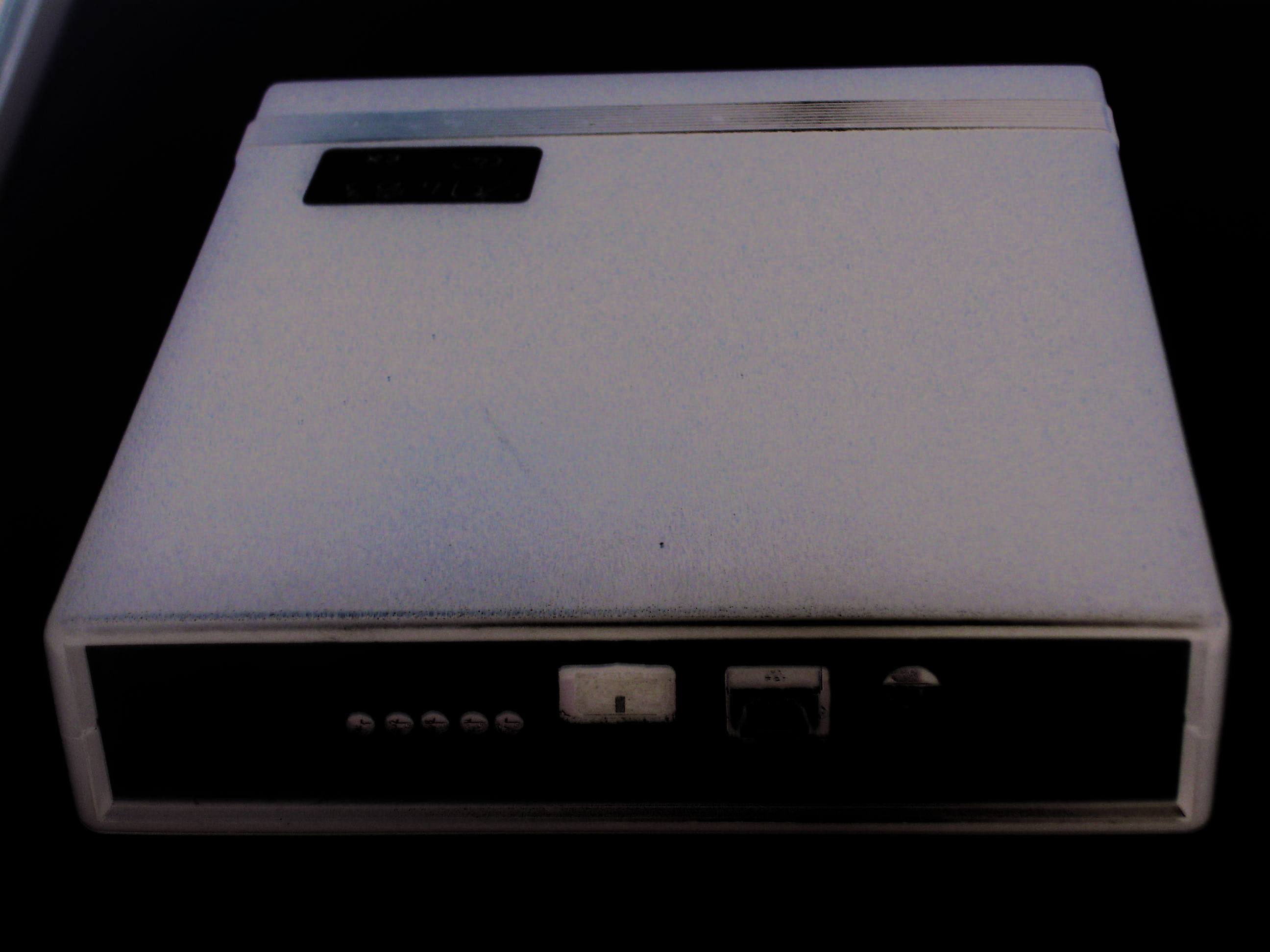
www.debgroup.com 1135-100 HUB MODE & GATEWAY MODE INSTALLATION & OPERATION GUIDE This device complies with Part 15 of the FCC Rules. Operation is subject to the following two conditions: (1) this device may not cause harmful interference, and (2) this device must accept any interference received, including interference that may cause undesired operation www.debgroup.com INTRODUCTION FEATURES CONNECTIONS The Deb Dispenser monitoring system is intended to provide remote monitoring of soap dispenser activations. Within the system the modules in Hub mode function as rebroadcasters, while those in Gateway mode relay the data messages to a server using either a USB cable or a modem. The system operates using the license free (ISM) bands. 906 MHz Single Channel Radio• Reverse SMA external antenna• 8 hour battery back-up• Crystal controlled real time clock• 5 LED status indicators• Rear View DC Power input (Use Supplied power adaptor only) 6 Way Microfit connector programming & expansion header USB B connector for diagnostics/debug output on Hub & Gateway. Also for Gateway data message output. System reset SMA Antenna connector EU only SMA Antenna connector USA/CA only Front View USB connection for data output and • diagnostics RS232 connection for optional external • GPRS modem (not included) Storage for approx. 600 messages• 1135-200 DISPENSER TELEMETRY MODULE 1135-100 HUB / GATEWAY MODULE www.debgroup.com LED INDICATORS BATTERY BACK-UP GATEWAY MODE FCC INSTALLATION CONDITIONS The Hub / Gateway module includes a battery back-up system capable of maintaining basic message handling functions for approximately 8 hours (at typical usage rates) should the system lose power. The battery back-up system is only enabled when the power adaptor is connected to the module. The 1135-100 must operate with a separation distance of at least 20cm from all persons and must not be co-located or operating in conjunction with any other antenna or transmitter, except in accordance with FCC multi-transmitter product procedures. The 1135-100 is only certified for use with antenna type Mobile Mark PSKN3-925RS antenna (supplied), max gain 2.3 dBi. When the module is configured in Gateway mode the device must be connected to either a computer via the USB B interface or optionally to an approved external GPRS modem via a custom cable and the microfit connector. The Gateway module should be positioned according to the site survey to provide suitable radio coverage and if using the optional external GPRS modem also ensuring that the GPRS signal coverage is adequate for a reliable connection. When using the optional GPRS modem it should be installed in accordance with the manufacturers instructions. The Gateway requires a connection to DEB’s custom API server platform, either on the locally connected computer or via GPRS, to obtain the correct time / date and to off-load messages. If connection to the API server is lost, the gateway is capable of storing approximately 670 messages. Once the message store is full the gateway will stop receiving messages. Power On / Device active - Flashes to 1. show unit is working. Gateway mode: GPRS connected. 2. Hub mode: Valid Route. Connection to server - Gateway only.3. Messages stored in device memory.4. Messages currently being received via 5. low power radio. Front View www.debgroup.com CONTACT DETAILS INSTALLATION RECOMMENDATIONS STANDARD OPERATION When the module is configured in Hub mode the device acts as a simple rebroadcaster, in that it receives messages from the dispenser modules over the predetermined wireless channel and then rebroadcasts them over that same wireless channel to be received by either another hub or the gateway module. When in Hub mode the device needs to be able to connect either directly to a Gateway or via another Hub that has already established a valid route to a Gateway, this ensures that the rebroadcast data can be successfully pushed through and out of the system. The Hub module should be positioned according to the site survey to provide suitable radio coverage, with consideration given to minimising the number of overlapping Hub coverage zones. Hubs are limited to a maximum of 5 rebroadcast ‘hops’ to the Gateway, as shown in the diagram below. There are no restrictions on the number of Hubs connected to the Gateway. The Hub and Gateway modules should preferably be installed in locations that are secure and not accessible by the general public. Ideal locations include maintenance closets, electrical closets and data / communication rooms. In all installs it is preferable for the module to be mounted as close to the ceiling as possible, keeping potential physical contact and tampering to a minimum. Use the alcohol wipe provided to clean and prepare both the wall and hub/gateway module. Leave to dry for 5 minutes. Apply 2 adhesive pads to the rear of the hub/gateway module. Using firm pressure mount the module to the wall. Hubs rebroadcast stored messages on through the system after a predetermined period of radio silence or when the message buffer is full. (Approximately 600 messages) For all product enquiries please contact your local DEB company. Full contact details can be found at: www.debgroup.com 1 HOP 5 HOPS 4 HOPS 3 HOPS 2 HOPS GPRS MODEM ISOPROP ANOL 50% 2ml
HUB / GATEWAY BOARD LABEL ‘bar code’ HUB: ‘serial number’ Trade Name: DEB Model No: 1135-100V2H FCC ID: YPHDEB1135-100 ‘bar code’ GATEWAY: ‘serial number’ Trade Name: DEB Model No: 1135-100V2G FCC ID: YPHDEB1135-100 ‘bar code’ GATEWAY: ‘serial number’ Trade Name: DEB Model No: 1135-100V2G FCC ID: YPHDEB1135-100 1.5”1.5” 0.75”0.75” 2” 2” 2” 2” HUB ID: **** ‘bar code’ ‘serial number’ FCC ID: YPHDEB1135-100 GATEWAY ID: **** ‘bar code’ ‘serial number’ FCC ID: YPHDEB1135-100 GATEWAY ASSEMBLY LABEL HUB ASSEMBLY LABEL HUB / GATEWAY ASSEMBLY LABEL POSITION SCALE 1:2 LABEL FIXED TO UNDERSIDE OF ENCLOSURE GATEWAY ID: **** ‘bar code’ ‘serial number’ FCC ID: YPHDEB1135-100
1135-100 MPE Calculation - OET Bulletin 65 FCC ID: YPHDEB1135-100 The FCC requires that the calculated MPE be equal to or less than a given limit dependent on frequency at a distance of 20 cm from a device to the body of a user. The MPE calculation as given in FCC OET Bulletin 65, page 19 is used to calculate the safe operating distance for the user. The transmitter for the 1135-100 operates at 906 MHz CALCULATION From OET Bulletin 65 the following far field power density equation is applicable: S = EIRP/4 π R 2 Where S = Power density EIRP = Effective Isotropically Radiated Power (EIRP = P x G) P = Conducted Transmitter Power G = Antenna Gain (relative to an isotropic radiator) R = distance to the centre of radiation of the antenna Requirement From table 1 (b) - Limits for General Population/ Uncontrolled Exposure of FCC Rule Part 1.1310 for 1,500-100,000MHz S = f/1500 = 0.604 mW/cm 2 Calculation for 20cm safe distance Values: P = 436.52 mW* (26.4 dBm); G= 2.35 dBi ∴EIRP = 749.84 mW (28.75 dBm); R = 20cm *Measured conducted power S = EIRP/4 π R 2 S = 749.84/(12.56 x 20 2 ) = 749.84/5024 S = 0.149 mW/cm 2 Conclusion The 1135-100 at 20 cm meets the required OET Bulletin 65 RF exposure requirements.
14 1/2 wave Device Antennas Single Band 800/900 MHz & 1.8/1.9 GHz Specifications Frequency: See above Gain: 2.3 dBi max VSWR: 2:1 over band Impedance: 50 Ohm nominal Maximum Power: 10 Watts Connector: See models above Whip Length Straight: 900 & 925 Series 9" (229 mm) when straight 1800 & 1900 Series: 7.8" (198 mm)when straight Whip Length 90 o : 900 & 925 Series 7.9" (201mm) when right angle 1800 & 1900 Series: 6.5" (165 mm) when right angle Right Angle Standoff: 1.25" (32 mm) inside elbow 1.75" (45 mm) outside elbow Operating Temp: -40 o to +85 o C Case Material: Polyurethane Please consult factory for special configurations & fre- quency bands. These antennas require no ground plane for operation. This makes them ideal for use with portable devices or products with no substantial groundplane. They can even be used with products that consist of all plastic chassis or case. The PSKN Series antennas use a full length center fed dipole configuration. A knuckle feature allows the antenna to be adjusted between a straight position, to a 90 o right angle position. This is useful for products that may need to be placed both horizontal and vertical, or where the connector is placed on the side of a radio device. Series PSN3 provides the antennas in a fixed straight position. Maximum radiation is achieved along the horizon, and bandwidth provided is substantial. VSWR is typically 2:1 or better over the desired frequency range. The antennas are available in many popular frequency bands. The radome is made of flexible Polyurethane. Standard connector styles available include TNC or SMA. For FCC part 15 compliance, select models offer reverse polarity connectors. PSKN Adjustable Series ■ Up to 2.3 dBi gain styles with semi-flexible radome and adjustable knuckle ■ Halfwave design requires no groundplane ■ Models for popular bands including Cellular, Mobitex, ISM, GSM, 802.11b/g ■ Sleek molded profile, with a choice of SMA or TNC connectors Model Numbers - TNC Male Connectors Model Typical Use Frequency PSKN3-900T 850 Cellular 806-894 MHz PSKN3-925T EU GSM/ISM 915 870-960 MHz PSKN3-1800T EU DCS-1800 1710-1880 MHz PSKN3-1900T US 1.9 GHz PCS 1850-1990 MHz PSN3-925T ISM 915 band 870-960 MHz Model Numbers - SMA Male Connectors PSKN3-900S 850 Cellular 806-894 MHz PSKN3-925S EU GSM/ISM 915 870-960 MHz PSKN3-1800S EU DCS-1800 1710-1880 MHz PSKN3-1900S US 1.9 GHz PCS 1850-1990 MHz PSN3-925T ISM 915 band 870-960 MHz Model Numbers - Rev SMA Plug Connectors PSKN3-925RS ISM 915 band 870-960 MHz PSN3-925RS ISM 915 band 870-960 MHz Model Numbers - Rev TNC Plug Connectors PSKN3-925RT ISM 915 band 870-960 MHz All models with "-925" also operate on ISM 902-928. 2.4 GHz WiFi versions also available, see other specs. US Office & Headquarters: 3900-B River Road, Schiller Park, IL 60176 Tel: 800-648-2800 or 847-671-6690 Fax: 847-671-6715 UK Office: 106 Anglesey Business Park, Hednesford, Staffs. WS12 1NR UK Tel: (+44) 1543-878343 Fax: (+44) 1543-871714 Visit our web page at www.mobilemark.com. Specifications subject to change without notice (4/2008). SMA (L) & TNC (R) versions Product Specifications PSN3 Fixed straight Model
TEST REPORT FROM RFI GLOBAL SERVICES LTD Test of: 1135-100 FCC ID: YPHDEB1135-100 To: FCC Part 15.247: 2010 Subpart C Test Report Serial No: RFI-RPT-RP79483JD05A This Test Report Is Issued Under The Authority Of Chris Guy, Head of Global Approvals: Checked By: Ian Watch Signature: Date of Issue: 22 June 2011 This report is issued in Adobe Acrobat portable document format (PDF). It is only a valid copy of the report if it is being viewed in PDF format with the following security options not allowed: Changing the document, Selecting text and graphics, Adding or changing notes and form fields. This report may not be reproduced other than in full, except with the prior written approval of RFI Global Services Ltd. The results in this report apply only to the sample(s) tested. TEST REPORT SERIAL NO: RFI-RPT-RP79483JD05A VERSION 2.0 ISSUE DATE: 22 JUNE 2011 Page 2 of 34 RFI Global Services Ltd This page has been left intentionally blank. TEST REPORT SERIAL NO: RFI-RPT-RP79483JD05A VERSION 2.0 ISSUE DATE: 22 JUNE 2011 RFI Global Services Ltd Page 3 of 34 Table of Contents 1. Customer Information .................................................................................................................. 4 2. Summary of Testing ..................................................................................................................... 5 2.1. General Information 5 2.2. Summary of Test Results 5 2.3. Methods and Procedures 6 2.4. Deviations from the Test Specification 6 3. Equipment Under Test (EUT) ....................................................................................................... 7 3.1. Identification of Equipment Under Test (EUT) 7 3.2. Description of EUT 7 3.3. Modifications Incorporated in the EUT 7 3.4. Additional Information Related to Testing 8 3.5. Support Equipment 8 4. Operation and Monitoring of the EUT during Testing ............................................................... 9 4.1. Operating Modes 9 4.2. Configuration and Peripherals 9 5. Measurements, Examinations and Derived Results ................................................................ 10 5.1. General Comments 10 5.2. Test Results 11 5.2.1. Receiver/Idle AC Conducted Spurious Emissions 11 5.2.2. Receiver/Idle Mode Radiated Spurious Emissions 14 5.2.3. Transmitter AC Conducted Spurious Emissions 18 5.2.4. Transmitter 6 dB Bandwidth 22 5.2.5. Transmitter 20 dB Bandwidth 23 5.2.6. Transmitter Peak Power Spectral Density 24 5.2.7. Transmitter Maximum Peak Output Power 25 5.2.8. Transmitter Radiated Emissions 26 5.2.9. Transmitter Radiated Emissions 28 5.2.10. Transmitter Band Edge Radiated Emissions 32 6. Measurement Uncertainty .......................................................................................................... 33 Appendix 1. Test Equipment Used ................................................................................................ 34 TEST REPORT SERIAL NO: RFI-RPT-RP79483JD05A VERSION 2.0 ISSUE DATE: 22 JUNE 2011 Page 4 of 34 RFI Global Services Ltd 1. Customer Information Company Name: DEB Address: Denby Hall Way Denby Derbyshire DE5 8JZ United Kingdom TEST REPORT SERIAL NO: RFI-RPT-RP79483JD05A VERSION 2.0 ISSUE DATE: 22 JUNE 2011 RFI Global Services Ltd Page 5 of 34 2. Summary of Testing 2.1. General Information Specification Reference: 47CFR15.247 Specification Title: Code of Federal Regulations Volume 47 (Telecommunications) 2010: Part 15 Subpart C (Intentional Radiators) - Section 15.247 Specification Reference: 47CFR15.107 and 47CFR15.109 Specification Title: Code of Federal Regulations Volume 47 (Telecommunications) 2010: Part 15 Subpart B (Unintentional Radiators) - Sections 15.107 and 15.109 Specification Reference: 47CFR15.207 and 47CFR15.209 Specification Title: Code of Federal Regulations Volume 47 (Telecommunications) 2010: Part 15 Subpart C (Intentional Radiators) - Sections 15.207 and 15.209 Site Registration: FCC: 209735 Location of Testing: RFI Global Services Ltd, Wade Road, Basingstoke, Hampshire, RG24 8AH. Test Dates: 18 April to 09 June 2011 2.2. Summary of Test Results FCC Reference (47CFR) Measurement Result Part 15.107(a) Receiver/Idle Mode AC Conducted Emissions Part 15.109 Receiver/Idle Mode Radiated Spurious Emissions Part 15.207 Transmitter AC Conducted Emissions Part 15.247(a)(2) Transmitter 6 dB Bandwidth Part 2.1049 Transmitter 20 dB Bandwidth Part 15.247(e) Transmitter Peak Power Spectral Density Part 15.247(b)(3) Transmitter Maximum Peak Output Power Part 15.247(d)/15.209(a) Transmitter Radiated Emissions Part 15.247(d) Transmitter Band Edge Radiated Emissions Key to Results = Complied = Did not comply TEST REPORT SERIAL NO: RFI-RPT-RP79483JD05A VERSION 2.0 ISSUE DATE: 22 JUNE 2011 Page 6 of 34 RFI Global Services Ltd 2.3. Methods and Procedures Reference: ANSI C63.4 (2009) Title: American National Standard for Methods of Measurement of Radio-Noise Emissions from Low-Voltage Electrical and Electronic Equipment in the Range of 9 kHz to 40 GHz. Reference: ANSI C63.10 (2009) Title: American National Standard for Testing Unlicensed Wireless Devices 2.4. Deviations from the Test Specification For the measurements contained within this test report, there were no deviations from, additions to, or exclusions from the test specification identified above. TEST REPORT SERIAL NO: RFI-RPT-RP79483JD05A VERSION 2.0 ISSUE DATE: 22 JUNE 2011 RFI Global Services Ltd Page 7 of 34 3. Equipment Under Test (EUT) 3.1. Identification of Equipment Under Test (EUT) Brand Name: DEB Model Name or Number: 1135-100 Serial Number: DCP131-021 (constant transmit sample) DCP131-022 (constant receive sample) Hardware Version Number: 3.0 Software Version Number: V1 FCC ID: YPHDEB1135-100 Description: Power supply unit Brand Name: Stontronics Model Name or Number: 3A-061WP05 Serial Number: T3916ST / 0832A Description: Antenna Brand Name: Mobile Mark Model Name or Number: PSKN3-925RS Serial Number: Not stated 3.2. Description of EUT The equipment under test wa…
Text truncated - open the document above for the full version.
| # | Rule Parts | Frequency Range | Power Output |
|---|---|---|---|
| 1 | 15C | 906 MHz - 906 MHz | 437.00 mW |

Telemetry Dispenser Module
Equipment Class
DSS - Part 15 Spread Spectrum Transmitter