FCCID.CO- FCC ID Database
HomeCompaniesEquipment ClassesSearch

© 2026 FCC ID Database. All rights reserved.

AboutContactData sourced from FCC public records
  1. Home/
  2. Deb IP Ltd/
  3. YPHDEB1135-200

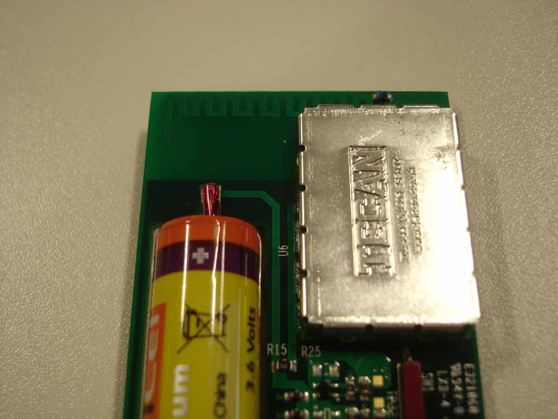
YPHDEB1135-200Telemetry Dispenser Module

Deb IP Ltd
Telemetry Dispenser Module - FCC ID YPHDEB1135-200 - Deb IP Ltd
Click to zoom

Application Details

Equipment Class
DSS - Part 15 Spread Spectrum Transmitter
Date of Grant
Oct 31, 2010
Application Purpose
Original Equipment
Date of Application
Oct 31, 2010
Equipment Note
Telemetry Dispenser Module
Frequency Range
905.00000000 - 905.00000000
Company
Deb IP Ltd
Country
United Kingdom

Documents & Files

Select a file to view
Users Manual

↗

Cover Letter(s)

↗
↗
↗
↗

External Photos

↗

ID Label/Location Info

↗

Internal Photos

↗

RF Exposure Info

↗

Test Report

↗

Test Setup Photos

↗

Document Text

Text extracted from the exhibit documents filed with the FCC. Open a document above to read the original.

Users Manual

www.debgroup.com 1135-200 DISPENSER TELEMETRY MODULE INSTALLATION & OPERATION GUIDE This device complies with Part 15 of the FCC Rules. Operation is subject to the following two conditions: (1) this device may not cause harmful interference, and (2) this device must accept any interference received, including interference that may cause undesired operation www.debgroup.com INTRODUCTION FEATURES TELEMETRY MODULE INSTALLATION The Deb Dispenser monitoring system is intended to provide remote monitoring of soap dispenser activations. The dispenser telemetry modules are intended for use as part of a larger system comprised of Hubs and Gateways (1135-100) along with a server. The system operates using the license free (ISM) bands. The Telemetry module is installed into the dispenser mechanism, along with the activation magnet. The complete dispenser mechanism assembly is then installed into the dispenser. 906 MHz Single Channel Radio• 250kbps QPSK• Integral PCB Antenna(-10dBi gain)• Duty Cycle 0.00025%• Reed Switch Activation• 5 Year Battery Life (100 activations • per day) Crystal Controlled Real Time Clock• 1135-200 DISPENSER TELEMETRY MODULE 1135-100 HUB / GATEWAY 1135-200 DISPENSER TELEMETRY MODULE BATTERY REED SWITCH MAGNET LED INDICATOR www.debgroup.com INSTALLATION MODE FCC LABELLING Prior to installation into the dispenser housing the Telemetry modules FCC approval label is visible on the back of the mechanics assembly. As this label is not visible when the mechanics assembly is installed into the dispenser housing a second label is attached to the underside of the unit. To aid installation a Light Emitting Diode (LED) is provided. To activate installation mode hold the mechanism in the activated position, as shown above, for approximately 5 seconds. Provided a working Gateway/Hub is in radio range the LED will flash slowly 5 times. Once installation mode has been activated the LED will flash briefly whenever a successful activation occurs. Installation mode is valid for 9 activations after which normal operation resumes. NOTE: During installation mode the normal 2.5 second activation window is not enabled and each individual dispense is treated as an activation. MAGNET POSITION AT REST LED MAGNET POSITION ACTIVATED SERIAL NO Trade Name: DEB Model No: 1135-200 FCC ID: YPHDEB1135-200 CONTAINS FCC ID: YPHDEB1135-200 www.debgroup.com CONTACT DETAILS STANDARD OPERATION STATE OF CHARGE MESSAGE During normal operation the dispenser is in a low power standby mode and is “woken” by an activation. This triggers a 2.5 second window during which subsequent activations are accumulated into a single event. The event is then time stamped in UTC format and transmitted to the nearest Gateway or Hub. Upon successful transmission the message is deleted and the unit returns to the low power standby mode. Messages that are failed to be acknowledged are stored and the dispenser attempts to retransmit the message(s) either on the next successful transmission or after 5 minutes. A maximum of 50 messages are stored. On retry the dispenser will enter broadcast mode in an attempt to locate a Gateway or Hub with a more reliable radio link. A daily state of charge message is transmitted that includes the calculated battery level provided there are no failed messages waiting to be transmitted. The time of day is randomised based on the address of the dispenser. During the transmission of the state of charge message the dispenser enters a broadcast mode to re-acquire the time and validates that it is connected to the Gateway or Hub with the highest signal strength. For all product enquiries please contact your local DEB company. Full contact details can be found at: www.debgroup.com

External Photos

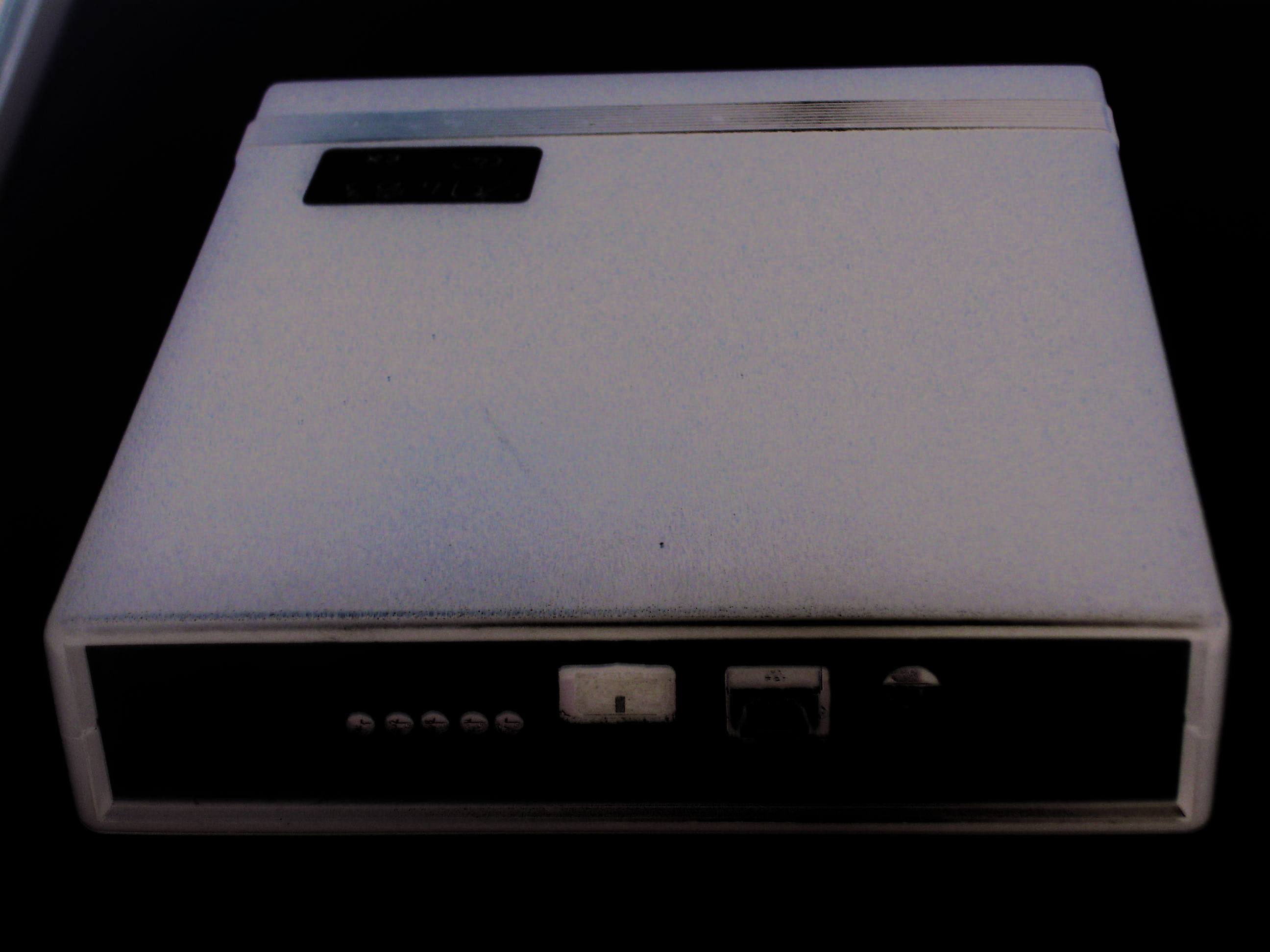
EXTERNAL PHOTO’S EXTERNAL PHOTO’S EXTERNAL PHOTO’S EXTERNAL PHOTO’S

ID Label/Location Info

(Serial No) xxxx Trade Name: DEB Model No: 1135‐200 FCC ID: YPHDEB1135‐200 Label artwork template ‐ Label Positioning ‐

Internal Photos

INTERNAL PHOTO’S INTERNAL PHOTO’S INTERNAL PHOTO’SINTERNAL PHOTO’S

Test Report

TEST REPORT FROM RFI GLOBAL SERVICES LTD Test of: DEB Dispenser Telemetry Module Model No. 1135-200 FCC ID: YPHDEB1135-200 To: FCC Part 15.247: 2009 Subpart C Test Report Serial No: RFI-RPT-RP78528JD01A This Test Report Is Issued Under The Authority Of Scott D’Adamo, Operations Manager Global Approvals: Checked By: Ian Watch Signature: Date of Issue: 16 August 2010 This report is issued in Adobe Acrobat portable document format (PDF). It is only a valid copy of the report if it is being viewed in PDF format with the following security options not allowed: Changing the document, Selecting text and graphics, Adding or changing notes and form fields. This report may not be reproduced other than in full, except with the prior written approval of RFI Global Services Ltd. The results in this report apply only to the sample(s) tested. TEST REPORT SERIAL NO: RFI-RPT-RP78528JD01A VERSION 2.0 ISSUE DATE: 16 AUGUST 2010 Page 2 of 20 RFI Global Services Ltd This page has been left intentionally blank. TEST REPORT SERIAL NO: RFI-RPT-RP78528JD01A VERSION 2.0 ISSUE DATE: 16 AUGUST 2010 RFI Global Services Ltd Page 3 of 20 Table of Contents 1. Customer Information .................................................................................................................. 4 2. Summary of Testing ..................................................................................................................... 5 3. Equipment Under Test (EUT) ....................................................................................................... 6 4. Operation and Monitoring of the EUT during Testing ............................................................... 7 5. Measurements, Examinations and Derived Results .................................................................. 8 6. Measurement Uncertainty .......................................................................................................... 19 Appendix 1. Test Equipment Used ................................................................................................20 TEST REPORT SERIAL NO: RFI-RPT-RP78528JD01A VERSION 2.0 ISSUE DATE: 16 AUGUST 2010 Page 4 of 20 RFI Global Services Ltd 1. Customer Information Company Name: TrimeriX Ltd Address: Unit 31 Cressex Enterprise Centre High Wycombe Buckinghamshire HP12 3RL United Kingdom TEST REPORT SERIAL NO: RFI-RPT-RP78528JD01A VERSION 2.0 ISSUE DATE: 16 AUGUST 2010 RFI Global Services Ltd Page 5 of 20 2. Summary of Testing 2.1. General Information Specification Reference: 47CFR15.247 Specification Title: Code of Federal Regulations Volume 47 (Telecommunications) 2009: Part 15 Subpart C (Intentional Radiators) - Section 15.247 Specification Reference: 47CFR15.107 and 47CFR15.109 Specification Title: Code of Federal Regulations Volume 47 (Telecommunications) 2009: Part 15 Subpart B (Unintentional Radiators) - Sections 15.107 and 15.109 Site Registration: FCC: 209735 Location of Testing: RFI Global Services Ltd, Wade Road, Basingstoke, Hampshire, RG24 8AH, United Kingdom Test Dates: 31 July 2010 2.2. Summary of Test Results FCC Reference (47CFR) Measurement Result Part 15.109 Receiver/Idle Mode Radiated Spurious Emissions Part 15.247(a)(2) Transmitter 6 dB Bandwidth Part 15.247(e) Transmitter Peak Power Spectral Density Part 15.247(b)(3) Transmitter Maximum Peak Output Power Part 15.247(d) & 15.209(a) Transmitter Radiated Emissions Part 15.247(d) & 15.209(a) Transmitter Band Edge Radiated Emissions Key to Results = Complied = Did not comply 2.3. Methods and Procedures Reference: ANSI C63.4 (2009) Title: American National Standard for Methods of Measurement of Radio-Noise Emissions from Low-Voltage Electrical and Electronic Equipment in the Range of 9 kHz to 40 GHz. Reference: ANSI C63.10 (2009) Title: American National Standard for Testing Unlicensed Wireless Devices 2.4. Deviations from the Test Specification For the measurements contained within this test report, there were no deviations from, additions to, or exclusions from the test specification identified above. TEST REPORT SERIAL NO: RFI-RPT-RP78528JD01A VERSION 2.0 ISSUE DATE: 16 AUGUST 2010 Page 6 of 20 RFI Global Services Ltd 3. Equipment Under Test (EUT) 3.1. Identification of Equipment Under Test (EUT) Description: Dispenser Telemetry Module Brand Name: DEB Model Name or Number: 1135-200 Serial Numbers: 20107587 (Transmit Mode) 20107390 (Receive Mode) Hardware Version Number: 1135-200 V1.0 Software Version Number: 1135-SW-200V1.0 FCC ID Number: YPHDEB1135-200 3.2. Description of EUT The equipment under test was a battery powered dispenser containing a telemetry module. 3.3. Modifications Incorporated in the EUT No modifications were applied to the EUT during testing. 3.4. Additional Information Related to Testing Tested Technology: Digitally modulated device operating in the 902 – 928 MHz band Power Supply Requirement: Nominal 3.3V Type of Unit: Transceiver Modulation: Digital Modulation Maximum Transmit ERP: 10.8 dBm (measured) Transmit Frequency Range: 905 MHz Channel ID Channel Frequency (MHz) Transmit Channels Tested: Single Channel 905 Receive Frequency Range: 905 MHz Channel ID Channel Frequency (MHz) Receive Channels Tested: Single Channel 905 TEST REPORT SERIAL NO: RFI-RPT-RP78528JD01A VERSION 2.0 ISSUE DATE: 16 AUGUST 2010 RFI Global Services Ltd Page 7 of 20 4. Operation and Monitoring of the EUT during Testing 4.1. Operating Modes The EUT was tested in the following operating mode(s): • Constantly transmitting at maximum power. • Receive / idle mode. 4.2. Configuration and Peripherals The EUT was tested in the following configuration(s): • Standalone • A new battery was fitted before testing commenced. The battery voltage was monitored throughout the testing and the battery replaced as required. TEST REPORT SERIAL NO: RFI-RPT-RP78528JD01A VERSION 2.0 ISSUE DATE: 16 AUGUST 2010 Page 8 of 20 RFI Global Services Ltd 5. Measurements, Examinations and Derived Results 5.1. General Comments Measurement uncertainti…

Text truncated - open the document above for the full version.

Contact Information

Applicant

Paul Dodds
[email protected]441773855100

Technical Contact

TrimerixNigel Gaylard
[email protected]44 844 567 0597

Unit 31 Cressex Enterpise Centre · High Wycombe · United Kingdom

Test Firm

UL VS LtdDarren Rust
[email protected]+44 1256 31 2119Fax: +44 1256 31 2001

Technical Specifications

#Rule PartsFrequency RangePower Output
115C905 MHz - 905 MHz12.00 mW
Modular Type
Single Modular Approval
Confidentiality
Long Term
Grant Notes
Power is ERP. Modular Approval. The antenna(s) used for this transmitter must not be co-located or operating in conjunction with any other antenna or transmitter, except in accordance with FCC multi-transmitter product procedures. OEM integrators and end-users must be provided with specific operating instructions for satisfying RF exposure compliance requirements.

Other Applications from Deb IP Ltd

GMS Dispenser Base Station Radio Interface - FCC ID YPHDEB1135-100 - Deb IP Ltd
YPHDEB1135-100

GMS Dispenser Base Station Radio Interface

Sep 11, 2011

Equipment Class

DSS - Part 15 Spread Spectrum Transmitter