YQ7-TN-UHF-Q300UHF read / write device
Hans Turck GmbH & Co. KG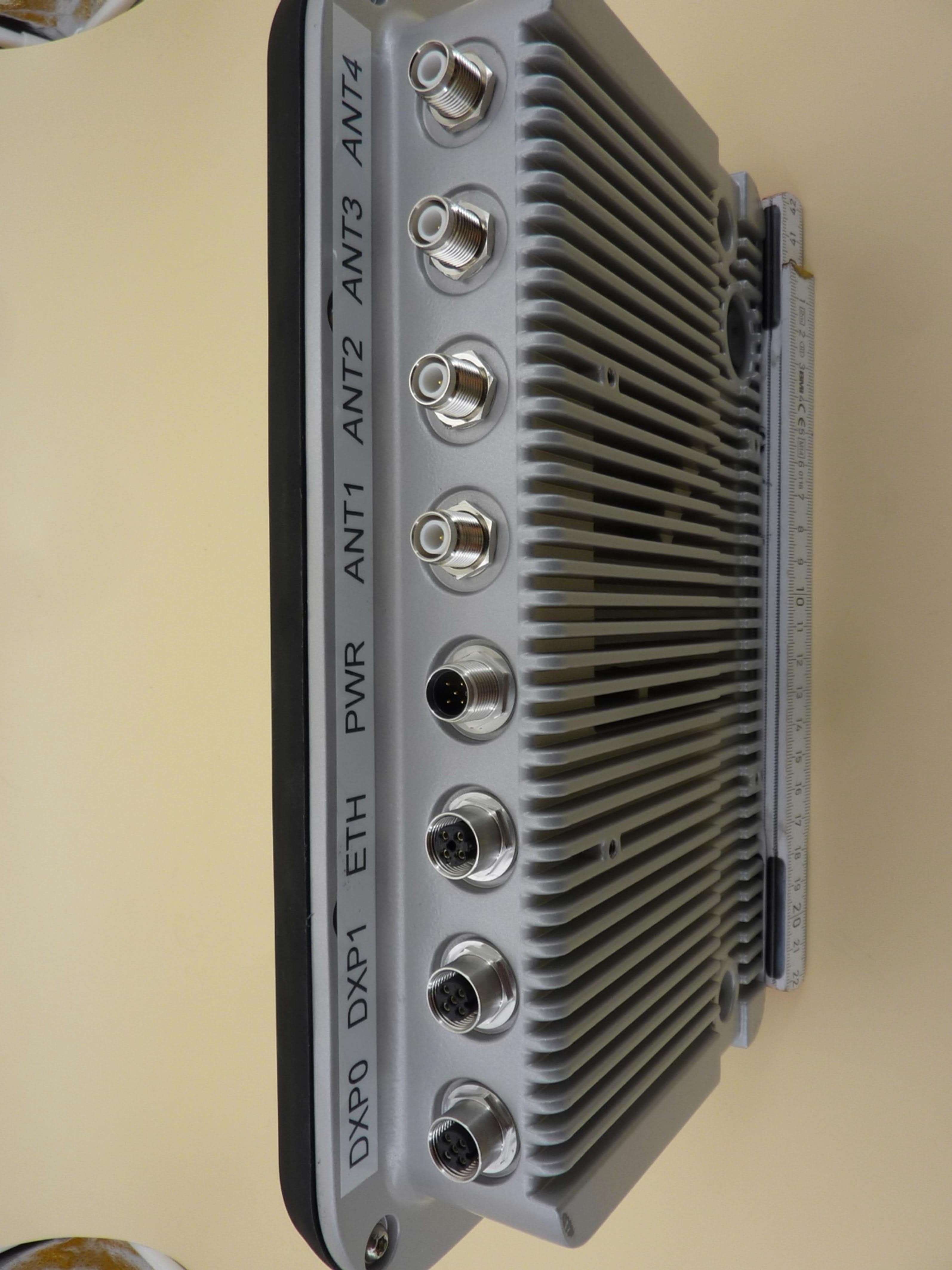
Click to zoom
Application Details
- Equipment Class
- JAD - Part 15 Class A Digital Device
- Date of Grant
- Nov 22, 2020
- Application Purpose
- Original Equipment
- Date of Application
- Nov 22, 2020
- Equipment Note
- UHF read / write device
- Company
- Hans Turck GmbH & Co. KG
- Country
- Germany
Documents & Files
Document Text
Text extracted from the exhibit documents filed with the FCC. Open a document above to read the original.
Users Manual
© Hans Turck GmbH & Co. KG | 100003061 2020-11 300 300 61.7 100 100 46.125 219 126 Ø 6.5 180 300 61.7 100 100 46.125 219 126 Ø 6.5 Wiring Diagrams 1 = V1 2 = TX/RX – 3 = GND 4 = TX/RX + 5 = PE 2 1 5 4 3 3 2 1 5 4 24 VDC / COM v 4 1 3 2 ETH/PoE 1 = TX + 2 = RX + 3 = TX – 4 = RX – ange = FE Supply voltageEthernet 4 1 3 2 5 v 1 = V aux 2 = DXP1 / DXP3 3 = GND 4 = DXP0 / DXP2 5 = FE DXP0...DXP3 5 FE 4 BK 1 BN + 3 BU – 3 BU – 2 WH v DXP0...DXP3 Sensor or Actuator Sensor or Actuator Digital channels (DXP0...DXP3) TN-UHF-Q...-NA... TN-UHF-Q...-NA... UHF Read/Write Head Quick Start Guide Doc-No. 100003061 2011 Additional information see turck.com Têtes de lecture/écriture TN-UHF-Q...-NA... Documents complémentaires Vous trouverez les documents suivants contenant des informations complémentaires à la présente notice sur notre site Web www.turck.com : ■ Fiche technique ■ Notice d’utilisation ■ Manuel de planification de projet RFID ■ Manuels de mise en service ■ Homologations Pour votre sécurité Utilisation correcte Les appareils sont conçus exclusivement pour une utilisation dans le domaine industriel. Les têtes de lecture/écriture avec interface RFID intégrée servent à échanger des données sans contact avec les supports de données BL ident dans le système RFID UHF Turck. La fréquence de fonctionnement des présents appareils est comprise entre 902 et 928 MHz. Les appareils doivent être employés uniquement dans les pays dans lesquels une plage de fréquence de 902-928 MHz est autorisée pour l’utilisation de RFID-UHF. Les interfaces RFID intégrées permettent aux têtes de lecture/écriture de communiquer directement avec la commande ou d’autres systèmes supérieurs. Les appareils doivent exclusivement être utilisés conformément aux indications figurant dans la présente notice. Toute autre utilisation est considérée comme non conforme. La société Turck décline toute responsabilité en cas de dommages causés par une utilisation non conforme. Consignes de sécurité générales ■ Seul un personnel qualifié est habilité à monter, installer, utiliser et entretenir l’appareil. ■ Les appareils répondent exclusivement aux exigences de la directive CEM pour le secteur industriel et ne sont pas destinés à être utilisés dans les zones d’habitation. ■ Une exposition prolongée dans la zone de rayonnement des têtes de lecture/écriture UHF peut avoir des conséquences néfastes sur la santé. Respectez les distances minimales requises par rapport à la surface de rayonnement de la tête de lecture/écriture. Région Puissance de rayonnement admissible max. Distance de sécurité États-Unis, Canada, Mexique 4 W EIRP> 0,35 m Description du produit Aperçu de l’appareil Voir Fig. 2 (TN-UHF-Q300...) et Fig. 3 (TN-UHF-Q180L300...) Fonctions et modes de fonctionnement Les appareils fonctionnent avec une antenne intégrée ou une antenne externe (TN-UHF- Q300...) ; ils fonctionnent uniquement avec une antenne externe (TN-UHF-Q180L300...) dans une gamme de fréquences de 902 ... 928 MHz. Les appareils permettent la lecture et l’écriture sur des supports de données UHF passifs fonctionnant avec une ou plusieurs étiquettes. Les appareils forment ainsi une zone de transmission dont l’étendue dépend, entre autres, des supports de données employés et des conditions d’utilisation dans le cadre de l’application. Les distances de lecture et d’écriture maximales sont indiquées dans les fiches techniques. Les interfaces RFID intégrées possèdent les fonctions suivantes : Désignation de typeFonctions TN-UHF-Q...-CDS ■ Interface multiprotocole pour les systèmes de bus de terrain PROFINET RT, Modbus TCP et EtherNet/IP ■ Programmable avec CODESYS 3 selon CEI 61131-3 TN-UHF-Q...-OPC-UA ■ Serveur OPC UA intégré pour la communication avec les systèmes tiers tels que les systèmes ERP TN-UHF-Q...-LNX ■ Programmable avec C, C++, NodeJS ou Python via le système d'exploitation Linux ■ Possibilité d'intégrer des fonctions d'intergiciel sur l'appareil Les capteurs et les actionneurs peuvent être raccordés aux canaux numériques configurables. Au total, il est possible de raccorder jusqu’à quatre capteurs PNP à 3 fils ou deux actionneurs PNP CC avec un courant de sortie maximal de 0,5 A par sortie. Le courant de sortie de tous les appareils connectés aux canaux DXP ne doit pas dépasser 1 A au total. Montage L’appareil est conçu pour être monté sur un support conformément à la norme VESA 100 × 100. Pour le montage, l’appareil dispose de 4 trous filetés M4 avec un écart de 100 mm (horizontal et vertical). La longueur maximale des vis est de 8 mm à laquelle s’ajoute la longueur du support VESA. Il est possible de monter les appareils dans n’importe quel sens. ➤Fixez l’appareil à un support à l’aide de 4 vis M4 conformément à la norme VESA 100 × 100. Raccordement En mode PoE (Power over Ethernet), les canaux numériques ne peuvent pas être utilisés comme sorties. ➤Raccordez l’appareil au bus de terrain selon les schémas de câblage « Wiring Diagrams » (couple de serrage max. 0,8 Nm). ➤Raccordez l’appareil à l’alimentation selon les schémas de câblage « Wiring Diagrams » (couple de serrage max. 0,8 Nm). ➤Branchez les capteurs numériques et les actionneurs à l’appareil selon les schémas de câblage « Wiring Diagrams » (couple de serrage max. 0,8 Nm). ➤Raccordez les antennes externes à l’appareil avec un câble d’antenne RP-TNC (couple de serrage max. 0,8 Nm). FR Guide d’utilisation rapide TN-UHF-Q...-NA... Read/Write Heads Other documents Besides this document the following material can be found on the Internet at www.turck.com: ■ Data sheet ■ Operating instructions ■ RFID configuration manual ■ Commissioning manuals ■ Approvals For your safety Intended use The devices are designed only for use in industrial areas. The read/write heads with integrated RFID interface are used as a means of contactless data exchange with BL ident tags within the Turck-UHF-RFID system. The operating frequency of the devices is 902–928 MHz. The devices may be operated only in countries in whi…
Text truncated - open the document above for the full version.
Cover Letter(s)
Page 1 of 1 PHOENIX TESTLAB GmbH Product Certification Department Koenigswinkel 10 32825 Blomberg, Germany Power of Attorney To Whom It May Concern: Please be advised that we, Hans Turck GmbH & Co. KG, authorize the following persons from PHOENIX TESTLAB GmbH: Sabrina Berghahn to act on our behalf in all matters relating to application for equipment authorization, including the signing of all documents relating to these matters and in-country-testing in the following countries: USA Canada PHOENIX TESTLAB GmbH has our permission to use our technical documents for the approvals for the following name device: Product description: UHF-RFID read / write device FCC ID: YQ7-TN-UHF-Q300 IC: 8821A-TNUHFQ300 PMN: TN-UHF-Q300-NA Series TN-UHF-Q180L300-NA Series HVIN: V2 FVIN: V1.0.2.0 Unless future correspondence from Hans Turck GmbH & Co. KG, please extend your full cooperation to PHOENIX TESTLAB GmbH regarding matters to the above mentioned products to 12 months after the signatory date of this authorization. Contact person Dr. Matthias Linde Position in the company Manager Approvals Date of signatory 11.02.2020 __________________________ Signatory (signature of the applicant)
Cover Letter(s)
page 1 of 4 DECLARATION OF IDENTITY Hereby we: Hans Turck GmbH & Co. KG Witzlebenstr. 7 D-45472 Mülheim an der Ruhr (Name of Manufacturer) declare that the Schematics, PCB Layout, Electrical Parts including the radio frequency parameters of the following products are identical to the basic model: Basic Model Number: FCC ID: YQ7-TN-UHF-Q300 IC: 8821A-TNUHFQ300 PMN: TN-UHF-Q300-NA-CDS HVIN: V2 FVIN: V1.0.2.0 Basic Test Report Number: F192159E1 Derivation Model Number: TN-UHF-Q300-NA-WIN TN-UHF-Q300-NA-LNX TN-UHF-Q300-NA-OPC TN-UHF-Q300-NA-H1147 TN-UHF-Q180L300-NA-CDS TN-UHF-Q180L300-NA-WIN TN-UHF-Q180L300-NA-LNX TN-UHF-Q180L300-NA-OPC page 2 of 4 Differences between the basic model and the derivation models: Model Number Differenc to basic model TN-UHF-Q300-NA-WIN operating system is WINDOWS instead of CoDeSys TN-UHF-Q300-NA-LNX operating system is LINUX instead of CoDeSys TN-UHF-Q300-NA-OPC operating system is LINUX with an OPC-UA server regarding AIM Companion Spec. v1.1 TN-UHF-Q300-NA-H1147 without Ethernet device (no Operating system) TN-UHF-Q180L300-NA-CDS Device without internal antenna – so the housing has smaller dimensions (180mm x 300mm) see photos on next pages! TN-UHF-Q180L300-NA-WIN Device without internal antenna – so the housing has smaller dimensions (180mm x 300mm) see photos on next pages! operating system is WINDOWS instead of CoDeSys TN-UHF-Q180L300-NA-LNX Device without internal antenna – so the housing has smaller dimensions (180mm x 300mm) see photos on next pages! operating system is LINUX instead of CoDeSys TN-UHF-Q180L300-NA-OPC operating system is LINUX with an OPC-UA server regarding AIM Companion Spec. v1.1 Model Number IC Certification Number TN-UHF-Q300-NA-CDS 8821A-TNUHFQ300 TN-UHF-Q300-NA-WIN TN-UHF-Q300-NA-LNX TN-UHF-Q300-NA-OPC TN-UHF-Q300-NA-H1147 TN-UHF-Q180L300-NA-CDS TN-UHF-Q180L300-NA-WIN TN-UHF-Q180L300-NA-LNX TN-UHF-Q180L300-NA-OPC Signature Printed name Markus Teubner Date 2020-11-18 page 3 of 4 Photos TN-UHF-Q300 TN-UHF-Q180L300 page 4 of 4 TN-UHF-Q300 TN-UHF-Q180L300
Cover Letter(s)
Federal Communications Commission 445 12 th Street, SW Washington, DC 20554 20-Nov-2020 Long/Short-term Confidentiality Request FCC ID: YQ7-TN-UHF-Q300 To Whom It May Concerns, Pursuant to sections 0.457(d) and 0.459 of CFR 47 and to avoid premature release of sensitive information prior to marketing or release of the product to the public, we hereby request long-term confidential treatment of information accompanying this application as outlined below: ☒ Schematics ☐ Parts List ☒ Block Diagram ☐ Tune-Up Info ☒ Operational Description In addition we hereby request the following exhibits contained in this application to be temporarily (short-term confidentiality) withheld from the public disclosure ☐ for an initial period of days ☐ until: ☒ not applicable ☐ External Photos ☐ Test Setup Photos ☐ Internal Photos ☐ Users Manual The above materials contain trade secrets and proprietary information not customarily released to the public. The public disclosure of these matters might be harmful to the applicant and provide unjustified benefits to its competitors. The applicant understands that pursuant to rule 0.457(d), disclosure of this application and all accompanying documentation will not be made before the date of the GRANT for this application. If you have any questions, please feel free to contact me. Yours sincerely, Sabrina Berghahn (Authorized Agent)
Cover Letter(s)
Hans Turck GmbH & Co. KG | 45466 Mülheim an der Ruhr, Germany | T +49 208 4952-0 | F +49 208 4952-264 | [email protected] | www.turck.com1|1 TN-UHF-ANT-Q140-EU-NA | 21-05-2019 10-09 | Technical modifications reserved TN-UHF-ANT-Q140-EU-NA External Passive UHF Antenna Technical data TypeTN-UHF-ANT-Q140-EU-NA Ident. no.100003864 Operating frequency865...928 MHz Antenna polarizationRHCP Antenna gain ETSI4.5 dBic± 0.5 dBic at 865-870 MHz Antenna gain FCC5.5 dBic± 0.5 dBic at 902–928MHz Antenna HPBW85° Ambient temperature-55...+70 °C Storage temperature-55...+70 °C Dimensions140 x 140 x 26 mm Housing materialPlastic Electrical connectionRP-TNC Input impedance50 Ohm Packaging unit1 Features ■ Rectangular, height 140 mm ■ Passive UHF Antenna ■ Polarized circular ■ Device suitable for global operation (EU and FCC) at 865...928 MHz Functional principle The UHF read/write heads form a transmission zone, the size of which may vary depending on the combination of read/write head and data carrier used. Attainable distances may vary due to component tolerances, mounting conditions, ambient conditions and material qualities, especially when mounted in metal. Testing of the application under real operating conditions is therefore essential, especially with on-the-fly reading and writing! Accessories TypeIdent. no. T-UHF-CBL-RG58-RPTNC-5-RPTNC100004374RG58 coaxial cable, length 5 m, RP-TNC to RP-TNC ethernet based transceiversEthernet based transceivers
External Photos
External photographs of TN-UHF-Q180L300-NA Series Examiner:Thomas KÜHNRevision:00 Date of issue: 06.11.2020Order Number: 19-112159page 1 of 4 TN-UHF-Q180L300-NA-CDS, 3-D-view 1 External photographs of TN-UHF-Q180L300-NA Series Examiner:Thomas KÜHNRevision:00 Date of issue: 06.11.2020Order Number: 19-112159page 2 of 4 TN-UHF-Q180L300-NA-CDS, 3-D-view 2 External photographs of TN-UHF-Q180L300-NA Series Examiner:Thomas KÜHNRevision:00 Date of issue: 06.11.2020Order Number: 19-112159page 3 of 4 TN-UHF-Q180L300-NA-CDS, connector view External photographs of TN-UHF-Q180L300-NA Series Examiner:Thomas KÜHNRevision:00 Date of issue: 06.11.2020Order Number: 19-112159page 4 of 4 TN-UHF-Q180L300-NA-CDS, type plate view
External Photos
External photographs of TN-UHF-Q300-NA Series Examiner:Thomas KÜHNRevision:00 Date of issue: 06.11.2020Order Number: 19-112159page 1 of 3 TN-UHF-Q300-NA-CDS, 3-D-view 1 External photographs of TN-UHF-Q300-NA Series Examiner:Thomas KÜHNRevision:00 Date of issue: 06.11.2020Order Number: 19-112159page 2 of 3 TN-UHF-Q300-NA-CDS, 3-D-view 2 External photographs of TN-UHF-Q300-NA Series Examiner:Thomas KÜHNRevision:00 Date of issue: 06.11.2020Order Number: 19-112159page 3 of 3 TN-UHF-Q300-NA-CDS, connector view
ID Label/Location Info
Lable Location Info TN-UHF-Q300-NA Series Lable Location Info TN-UHF-Q180L300-NA Series
Internal Photos
Internal photographs of TN-UHF-Q180L300-NA Series Examiner:Thomas KÜHNRevision:00 Date of issue: 06.11.2020Order Number: 19-112159page 1 of 9 TN-UHF-Q180L300-NA-CDS, internal view 1 (housing opened) Internal photographs of TN-UHF-Q180L300-NA Series Examiner:Thomas KÜHNRevision:00 Date of issue: 06.11.2020Order Number: 19-112159page 2 of 9 TN-UHF-Q180L300-NA-CDS, internal view 2 (shield removed) Internal photographs of TN-UHF-Q180L300-NA Series Examiner:Thomas KÜHNRevision:00 Date of issue: 06.11.2020Order Number: 19-112159page 3 of 9 TN-UHF-Q180L300-NA-CDS, internal view 3 (PCBs removed) Internal photographs of TN-UHF-Q180L300-NA Series Examiner:Thomas KÜHNRevision:00 Date of issue: 06.11.2020Order Number: 19-112159page 4 of 9 TN-UHF-Q180L300-NA-CDS, shield, top view Internal photographs of TN-UHF-Q180L300-NA Series Examiner:Thomas KÜHNRevision:00 Date of issue: 06.11.2020Order Number: 19-112159page 5 of 9 TN-UHF-Q180L300-NA-CDS, shield, bottom view Internal photographs of TN-UHF-Q180L300-NA Series Examiner:Thomas KÜHNRevision:00 Date of issue: 06.11.2020Order Number: 19-112159page 6 of 9 TN-UHF-Q180L300-NA-CDS, rf PCB, top view Internal photographs of TN-UHF-Q180L300-NA Series Examiner:Thomas KÜHNRevision:00 Date of issue: 06.11.2020Order Number: 19-112159page 7 of 9 TN-UHF-Q180L300-NA-CDS, rf PCB, bottom view Internal photographs of TN-UHF-Q180L300-NA Series Examiner:Thomas KÜHNRevision:00 Date of issue: 06.11.2020Order Number: 19-112159page 8 of 9 TN-UHF-Q180L300-NA-CDS, digital PCB, top view Internal photographs of TN-UHF-Q180L300-NA Series Examiner:Thomas KÜHNRevision:00 Date of issue: 06.11.2020Order Number: 19-112159page 9 of 9 TN-UHF-Q180L300-NA-CDS, digital PCB, bottom view
Internal Photos
Internal photographs of TN-UHF-Q300-NA Series Examiner:Thomas KÜHNRevision:00 Date of issue: 06.11.2020Order Number: 19-112159page 1 of 12 TN-UHF-Q300-NA-CDS, internal view 1 (housing opened) Internal photographs of TN-UHF-Q300-NA Series Examiner:Thomas KÜHNRevision:00 Date of issue: 06.11.2020Order Number: 19-112159page 2 of 12 TN-UHF-Q300-NA-CDS, internal view 2 (antenna removed) Internal photographs of TN-UHF-Q300-NA Series Examiner:Thomas KÜHNRevision:00 Date of issue: 06.11.2020Order Number: 19-112159page 3 of 12 TN-UHF-Q300-NA-CDS, internal view 3 (PCBs removed) Internal photographs of TN-UHF-Q300-NA Series Examiner:Thomas KÜHNRevision:00 Date of issue: 06.11.2020Order Number: 19-112159page 4 of 12 TN-UHF-Q300-NA-CDS, antenna coupler PCB, top view Internal photographs of TN-UHF-Q300-NA Series Examiner:Thomas KÜHNRevision:00 Date of issue: 06.11.2020Order Number: 19-112159page 5 of 12 TN-UHF-Q300-NA-CDS, antenna coupler PCB, bottom view Internal photographs of TN-UHF-Q300-NA Series Examiner:Thomas KÜHNRevision:00 Date of issue: 06.11.2020Order Number: 19-112159page 6 of 12 TN-UHF-Q300-NA-CDS, antenna director PCB, top view (supplied by the applicant) Internal photographs of TN-UHF-Q300-NA Series Examiner:Thomas KÜHNRevision:00 Date of issue: 06.11.2020Order Number: 19-112159page 7 of 12 TN-UHF-Q300-NA-CDS, antenna director PCB, bottom view (supplied by the applicant) Internal photographs of TN-UHF-Q300-NA Series Examiner:Thomas KÜHNRevision:00 Date of issue: 06.11.2020Order Number: 19-112159page 8 of 12 TN-UHF-Q300-NA-CDS, rf PCB, top view Internal photographs of TN-UHF-Q300-NA Series Examiner:Thomas KÜHNRevision:00 Date of issue: 06.11.2020Order Number: 19-112159page 9 of 12 TN-UHF-Q300-NA-CDS, rf PCB, bottom view Internal photographs of TN-UHF-Q300-NA Series Examiner:Thomas KÜHNRevision:00 Date of issue: 06.11.2020Order Number: 19-112159page 10 of 12 TN-UHF-Q300-NA-CDS, digital PCB, top view Internal photographs of TN-UHF-Q300-NA Series Examiner:Thomas KÜHNRevision:00 Date of issue: 06.11.2020Order Number: 19-112159page 11 of 12 TN-UHF-Q300-NA-CDS, digital PCB, bottom view Internal photographs of TN-UHF-Q300-NA Series Examiner:Thomas KÜHNRevision:00 Date of issue: 06.11.2020Order Number: 19-112159page 12 of 12 TN-UHF-Q300-NA-CDS, antenna director inside top housing
Test Report
Königswinkel 10 32825 Blomberg, Germany Phone: +49 (0) 52 35 / 95 00-0 Fax:+49 (0) 52 35 / 95 00-10 [email protected] www.phoenix-testlab.de Test Report Report Number: F192159E2 Equipment under Test (EUT): TN-UHF-Q300-NA Series Applicant: Werner Turck GmbH & Co. KG Manufacturer: Hans Turck GmbH & Co. KG Examiner:Thomas KÜHNReport Number: F192159E2 Date of Issue: 17.08.2020Order Number: 19-112159Page 2 of 19 References [1]ANSI C63.4:2014 American National Standard for Methods of Measuring of Radio-Noise Emissions from Low-Voltage Electrical and Electronic Equipment in the Range of 9 kHz to 40 GHz. [2] FCC 47 CFR Part 2:General Rules and Regulations [3]FCC 47 CFR Part 15:Radio Frequency Devices (Subpart B) [4]ICES-003 Issue 6: (January 2016)Spectrum Management and Telecommunications. Interference-Causing Equipment Standard. Information Technology Equipment (Including Digital Apparatus) —Limits and Methods of Measurement Test Result The requirements of the tests performed as shown in the overview (clause 4) were fulfilled by the equipment under test. The complete test results are presented in the following. This test report is only valid in its original form. Any reproduction of its contents in extracts without written permission of the accredited test laboratory PHOENIX TESTLAB GmbH is prohibited. The test results herein refer only to the tested sample. PHOENIX TESTLAB GmbH is not responsible for any generalisations or conclusions drawn from these test results concerning further samples. Any modification of the tested samples is prohibited and leads to the invalidity of this test report. Each page necessarily contains the PHOENIX TESTLAB Logo and the TEST REPORT NUMBER. Tested and written by:Thomas KÜHN17.08.2020 Name Signature Date Reviewed and approved by:Manuel BASTERT17.08.2020 Name Signature Date Examiner:Thomas KÜHNReport Number: F192159E2 Date of Issue: 17.08.2020Order Number: 19-112159Page 3 of 19 Contents:Page Identification ........................................................................................................................ 4 1.1Applicant ......................................................................................................................................... 4 1.2Manufacturer .................................................................................................................................. 4 1.3Test Laboratory .............................................................................................................................. 4 1.4EUT (Equipment under Test) ......................................................................................................... 5 1.5Technical data of equipment .......................................................................................................... 5 1.6Dates .............................................................................................................................................. 6 Operational States ............................................................................................................... 6 Additional Information .......................................................................................................... 7 Overview .............................................................................................................................. 7 Results................................................................................................................................. 8 5.1Conducted emissions on power supply lines ................................................................................. 8 5.1.1Test method ........................................................................................................................... 8 5.1.2Results conducted emission measurement on AC mains (EUT supplied via PoE) .............. 9 5.1.3Results conducted emission measurement on AC mains (EUT supplied via DC) .............. 10 5.2Radiated emissions ...................................................................................................................... 11 5.2.1Test method ......................................................................................................................... 11 5.2.2Result final measurement from 30 MHz to 1 GHz ............................................................... 14 5.2.3Result final measurement above 1 GHz .............................................................................. 16 Test Equipment used for Tests .......................................................................................... 18 Test site Validation ............................................................................................................ 19 Report History .................................................................................................................... 19 List of Annexes .................................................................................................................. 19 Examiner:Thomas KÜHNReport Number: F192159E2 Date of Issue: 17.08.2020Order Number: 19-112159Page 4 of 19 Identification 1.1 Applicant Name:Werner Turck GmbH & Co. KG Address: Goethestr. 7 58553 Halver Country:Germany Name for contact purposes:Mr. Sebastian SCHÜRMANN Phone:+49 2353 709-6216 Fax:+49 2353 709-6174 eMail address:[email protected] Applicant represented during the test by the following person: - 1.2 Manufacturer Name:Hans Turck GmbH & Co. KG Address: Witzlebenstraße 7 45472 Mülheim an der Ruhr Country:Germany Name for contact purposes:Dr. Matthias LINDE Phone:+49 2353 709-6198 Fax:+49 2353 709-6174 eMail address:[email protected] Manufacturer represented during the test by the following person: - 1.3 Test Laboratory The tests were carried out by:PHOENIX TESTLAB GmbH Königswinkel 10 32825 Blomberg Germany Accredited by Deutsche Akkreditierungsstelle GmbH (DAkkS) in compliance with DIN EN ISO/IEC 17025 under Reg. N…
Text truncated - open the document above for the full version.
Test Setup Photos
Annex A Test setup photos Examiner: Thomas KÜHNReport Number: F192159E2 Date of issue: 17.08.2020Order Number: 19-112159page 1 of 5 Test setup semi anechoic chamber Annex A Test setup photos Examiner: Thomas KÜHNReport Number: F192159E2 Date of issue: 17.08.2020Order Number: 19-112159page 2 of 5 Test setup semi anechoic chamber, measurement from 30 MHz to 1 GHz Annex A Test setup photos Examiner: Thomas KÜHNReport Number: F192159E2 Date of issue: 17.08.2020Order Number: 19-112159page 3 of 5 Test setup semi anechoic chamber, measurement from 1 GHz to 5 GHz Annex A Test setup photos Examiner: Thomas KÜHNReport Number: F192159E2 Date of issue: 17.08.2020Order Number: 19-112159page 4 of 5 Test setup shielded chamber (EUT PoE supplied) Annex A Test setup photos Examiner: Thomas KÜHNReport Number: F192159E2 Date of issue: 17.08.2020Order Number: 19-112159page 5 of 5 Test setup shielded chamber (EUT DC supplied)
Contact Information
Applicant
Matthias Linde(Representative Approvals)
Test Firm
PHOENIX TESTLAB GmbHHolger Bentje
Technical Specifications
| # | Rule Parts | Frequency Range | Power Output |
|---|---|---|---|
| 1 | 15B | - | - |
Other Applications from Hans Turck GmbH & Co. KG

YQ7-TN-UHF-Q150
Jul 04, 2026UHF RFID read/write device
Equipment Class
DSS - Part 15 Spread Spectrum Transmitter
YQ7-NICP-EM30
Dec 09, 2025Inductive Coupler NICP
Equipment Class
8CC - Part 18 Consumer Device
YQ7-NICS-EM30
Nov 28, 2025Inductive Coupler NICS
Equipment Class
JAD - Part 15 Class A Digital DeviceYQ7-MR15Q80
Aug 04, 2024Radar sensor
Equipment Class
FDS - Part 15 Field Disturbance Sensor
YQ7-LRS-510-10
May 18, 2021Radar Level Sensor
Equipment Class
DXX - Part 15 Low Power Communication Device Transmitter