YQESV-301MT900MHz Wireless Transmitter
Supreme Audio. Inc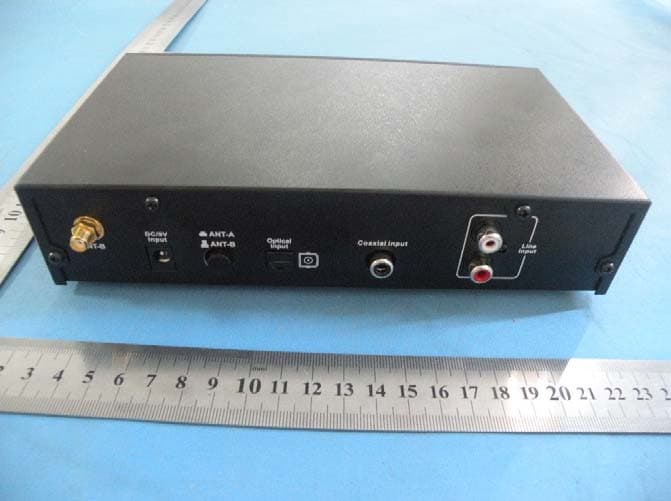
Click to zoom
Application Details
- Equipment Class
- DXX - Part 15 Low Power Communication Device Transmitter
- Date of Grant
- Sep 20, 2010
- Application Purpose
- Original Equipment
- Date of Application
- Sep 20, 2010
- Equipment Note
- 900MHz Wireless Transmitter
- Frequency Range
- 902.10000000 - 927.90000000
- Company
- Supreme Audio. Inc
- Country
- United States
Documents & Files
Document Text
Text extracted from the exhibit documents filed with the FCC. Open a document above to read the original.
Users Manual
USER’S MANUAL: SUPREMEVISION LARGE AREA 900MHZ WIRELESS TRANSMITTER Model No.: SV‐301MT Important Safety Instructions Read all instructions in this guide before installing and using the equipment. Use the supplied power supply with the equipment. Plug the power supply into an appropriate, grounded power outlet. Keep the equipment away from water an d moisture. Avoid d ropping anything on the equipment. Do not attempt to service the unit yourself. Contact your dealer or Supreme Audio directly for maintenance and replacements. Introduction Thanks for purchasing the SUPREMEVISION 900MHz wireless transmitter. This system is very reliable and easy to use. It is supported by a pr ofessional techni cal team who will ensure that, in the unlikely event that you strike any problems, you will be satisfied. Set the transmitter into any frequency freely ranged from 902.1MHz to 927 .9MHz. The transmitter is compatible with all 900MHz receivers worldwi de, such as Cardio Theater’s, BVE’s, MYE’s etc. Technical Specifications 900MHz Wireless Transmitter Frequency 902.100MHz ‐ 927.900MHz Output Power ‐8dbm Frequency space 50KHz Channel TBD Audio Sampling analog Current Draw DC9V 200mA Audio Frequency Response 50Hz~15KHz Mute audio mute when signal lost Concurrent Systems 20 Transmission Method FM Audio Input / Output Line Input, Digital Inputs (Coax. & Optical) Power 9V Power Adapter Configurations 1. ON/OFF Switch 2. Color TFT Display 3. Lock button 4. UP button 5. DOWN button 6. Digit 0‐9 & Decimal Button 7. Mode button (used to choose the audio source inputs, that is, coaxial input, fiber input or line input) 8. Memo button (used to memorize a new frequency) 9. ANT‐A (front antenna) 10. Set button 11. Enter button (used to confirm a new frequency) 12. ANT‐B (rear antenna) 13. DC/9V power input Jack 14. Antenna selection switch (used to choose the front or rear antenna) 15. Digital optical input jack 16. Digital coaxial input jack 17. Line input jack Programming Procedures Unlock by pressing the “LOCK” button till the lock icon disappears. Since all Freq’s start with ‘9’, the cursor defaults to the second digit. As you enter a digit for the new Frequency the cursor automatically moves to the right until you have entered all 5 digits after th e ‘9’. Then press “Enter”. The last digit is always zero, so it does not need to be changed. The decimal point is done automatically. If you make a mistake, you can start again or use the “UP”/ “Down” buttons to correct. Once you press “Enter”, the cursor will go away , and if you need to change, press “SET and start again. After inserting the wanted frequency, press “Enter” and then “Memory” to memorize the Frequency. Then the setting is done. “Mode” button: choose the inpu ts (digital coaxial input, digital fiber input or line input) The antenna selection switch: it has two depths. When you push it once, it goes deeper, and the system will use the front antenna. When you push it again, it is shallower, then the system chooses the rear antenna. Trouble Sh ooting Guide 1. When a STATIC INTERFERENCE occurs, please go through the following procedures to eliminate the problems. a. Sound level on TV or other audio source equipment may be too high. Check the equipment and adjust the sound level as needed. b. Check to see if any outside source s are usin g the same frequency as the transmitter. Either locate and remove the outside interference, or set the transmitter to a different channel to avoid that frequency. c. Check the antenna installation. Make sure the antenna selection is correct. Switch to the rear antenna if the front one doesn’t work , vice versa. Check the audio source cable. d. Make sure the transmitter mode is correct and the receiver channel number is correct. e. Check the sound by connecting it to a different transmitter. Listen from a receiver to see if the sound improves. f. Make sure the transmitter has po wer by chec king the AC power cord: Is it plugged into a nearly outlet and into the transmitter? g. Make sure that the antenna is upright and not located near a power cord or any metal objects. h. If the problem continues, unplug the power cord for five minutes, then plug in again 2. Wh en a NOISY SOUND occurs, please go through the following procedures to eliminate the problems. a. Make sure there are no major internal obstructions, such as metal support posts, between antenna and receiver. b. Make sure the antenna and receivers are installed so they are within the di stance ra nge. c. Make sure that the antenna is upright and not located near a power cord, audio cable, or any metal objects. d. Make sure the sound level on the TV or other audio source equipment connected to the transmitter is set to a reasonable, medium level. e. Try changing the transmitter to a different frequency to see if the sound quality improves. Some will be received better than others. It is suggested 300K fre quency space to ensure the audio quality. f. Make sure no other wireless transmitters are using the same frequency at the facility. The user is encouraged to use our Tri‐band wireless receiver to do an auto‐scanning in the field before the installation to find out the frequencies being used. Avoid using the frequencies being used whenever you install a new transmitter. g. Check to see if any outside sources are using the same frequency as the transmitter. Either locate and remove the outside interference, or change the transmitter to a different frequency to avoid that frequency. 3. When th ere is NO SOUND, pl ease go through the following procedures to eliminate the problems. a. Make sure the transmitter and the receiver frequency matches. b. Sound from the TV or other audio sources may be too low or muted. Check the equipment and increase the sound or unmute as needed. c. Make sure the transmitter mo de and the audio input jack matches. Check the audio cable to the TV “OUTPUT” not “INPUT”. d. Check the sound from the TV or other audio sources by connecting it to a…
Text truncated - open the document above for the full version.
Cover Letter(s)
Authorization Letter Number: CF101 Version: V01 Date: 01-02-2010 We, (the approval holder) Company name Supreme Audio. Inc Addresss 155 Troy Rd, PO Box 550, Marlborough, NH 03455-0550 City Marlborough Country Unite States declare that the following representative (agent): Name (person) Mark Zhu Company name Shenzhen Certification Technology Service Co.,Ltd Addresss 3F, Bldg.27, Area A, Tanglang Industrial Zone, Xili Town, Nanshan District, Shenzhen 518055, Guangdong, P.R. China City Shenzhen, Guangdong Country China is hereby authorized to apply the following equipment for certification on our behalf: Product Description 900MHz Wireless Transmitter Type or Model(s) SV-301MT Tradename or Brand(s) We also authorize Teleconformity to process this application. Attestation: City and Country: Date: Name: (this must be a person) Function: Signature: (or official company stamp) Marlborough August 21, 2010 William Heyman Director Shenzhen August 21, 2010 Mark Zhu Manage
Cover Letter(s)
FCC Confidentiality Request Number: CF303 Version: V01 Date: 01-02-2010 To the FCC and FCC TCB handling this application for certification Pursuant to 47 CFR Section 0.459(a) & (b), we, (the applicant / grantee) Company name Supreme Audio. Inc Addresss 155 Troy Rd, PO Box 550, Marlborough, NH 03455-0550 City Marlborough Country Unite States request non-disclosure and confidential treatment for our certification under: Grantee Code Product Number FCC ID: YQE SV-301MT of the following materials submitted within this certification application: (please cross what is applicable, or add other documents) x Operational Description x Block Diagrams x Schematics Diagrams Bill of Materials Above materials contain secrets, proprietary and technical information, which would customarily be guarded from competitors under 47 CFR, section 0.457(d)(2). Disclosure or publication or any portion of this company confidential material to other parties could cause substantial competitive harm and provide unjustified benefits for competitors. We understand that pursuant to 47 CFR section 0.457(d)(1)(ii) disclosure of the applicant and all accompanying documentation will not be made before the date of the grant. Attestation: City and Country: Date: Name: (this must be a person) Function: Signature: (or official company stamp) Marlborough August 21, 2010 William Heyman Director
External Photos
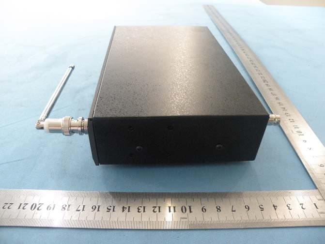
Full View To p Vi e w Bottom View Front View Left View Rear View Right View
ID Label/Location Info
FCC ID: YQESV-301MT This device complies with Part 15 of the FCC Rules. Operation is subject to the following two conditions: (1) this device may not cause harmful interference, and (2) this device must accept any interference received, including interference that may cause undesired operation.
ID Label/Location Info
Label Location
Internal Photos
Top View Bottom View ANTENNA
Test Report
主要技术参数 MAIN TECHNICAL SPECIFICATION 频率范围 Frequency range 900-1000 MHz 尺寸Dimension 105 3mm 输入阻抗Impedance50 接头 Connector SMA-J 驻波比VSWR2 外罩材料 Radome material ABS 增益 Gain 2DBi 外罩颜色 Radome color 黑色 Black 极化方向 Polarization 垂直 vertical 工作温度 Working temperature 辐射方向 Radiation 全向 all 存放温度 Stora ge temperature 功率容量 Maximun power Input-watts 50W
Test Report
Shenzhen Certification Technologh Service Co., Ltd 3F, Bldg27,Area A, Tanglang Industrial Zone, Xili Town, Nanshan District, ShenZhen, Guang dong, P.R. China. FCCID: YQESV-301MT Page 1 of 33 TEST REPORT FCC ID: YQESV-301MT Applicant : Supreme Audio. Inc Address : 155 Troy Rd, PO Box 550, Marlborough, NH 03455-0550 Equipment under Test (EUT): Name : 900MHz Wireless Transmitter Model : SV-301MT Standards : FCC PART 15, SUBPART C : 2009. (Section 15.249) Report No. : STE100809617 Date of Test : August 27, 2010 Date of Issue : August 21-27, 2010 Test Result : PASS * * In the configuration tested, the EUT complied with the standards specified above Authorized Signature (Mark Zhu) General Manager The manufacture should ensure that all the products in series production are in conformity with the product sample detailed in this report. If the product in this report is used in any configuration other than that detailed in the report, the manufacturer must ensure the new system complies with all relevant standards. Any mention of Shenzhen Certification Technology Service Co., Ltd. Or test done by Shenzhen Certification Technology Service Co., Ltd. Approvals in connection with, distribution or use of the product described in this report must be approved by Shenzhen Certification Technology Service Co., Ltd. Approvals in writing. Report No.:STE100809617 FCCID: YQESV-301MT Page 2 of 33 TABLE OF CONTENT Description Page 1 General Information------------------------------------------------------------------------------------- 3 1.1 Description of Device (EUT)------------------------------------------------------------------ 3 1.2 Description of Test Facility-------------------------------------------------------------------- 4 2 EMC Equipment List --------------------------------------------------------------------------------- 4 3 Test Procedure ----------------------------------------------------------------------------------------- 5 4 Summary of Measurement ------------------------------------------------------------------------- 6 5 POWER LINE CONDUCTED EMISSION -------------------------------------------------------- 7 5.1 Conducted Emission Limits(15.209&249)-------------------------------------------------7 5.2 Test Setup-----------------------------------------------------------------------------------------7 5.3 Test Procedure-----------------------------------------------------------------------------------8 5.4 Test Resluts---------------------------------------------------------------------------------------8 6 Radiation Emission---------------------------------------------------------------------------------- 10 6.1 Radiation Emission Limits(15.209&249 (a))--------------------------------------------- 10 6.2 Test Setup--------------------------------------------------------------------------------------- 11 6.3 Test Procedure--------------------------------------------------------------------------------- 12 6.4 Test Equipment Setting For emission test.est Result--------------------------------- 13 6.5 Test Condition---------------------------------------------------------------------------------- 13 6.6 Test Result-------------------------------------------------------------------------------------- 13 7 Occupied bandwidth -------------------------------------------------------------------------------- 18 7.1 Test limit------------------------------------------------------------------------------------------ 18 7.2 Method of measurement--------------------------------------------------------------------- 18 7.3 Test Setup--------------------------------------------------------------------------------------- 18 7.4 Test Results------------------------------------------------------------------------------------- 18 8 Band Edge Check------------------------------------------------------------------------------------ 22 8.1 Test limit------------------------------------------------------------------------------------------ 22 8.2 Test Procedure--------------------------------------------------------------------------------- 22 8.3 Test Setup--------------------------------------------------------------------------------------- 22 8.4 Test Result-------------------------------------------------------------------------------------- 22 9 Antenna Requirement ------------------------------------------------------------------------------ 25 9.1 Standard Requirement----------------------------------------------------------------------- 25 9.2 Antenna Connected Construction---------------------------------------------------------- 25 9.3 Result--------------------------------------------------------------------------------------------- 25 10 Photographs of Test Setup ----------------------------------------------------------------------- 26 11 Photographs of EUT--------------------------------------------------------------------------------- 28 Report No.:STE100809617 FCCID: YQESV-301MT Page 3 of 33 1 General Information 1.1 Description of Device (EUT) Trade Name : N/A EUT : 900MHz Wireless Transmitter Model No. : SV-301MT Type of Antenna : Type: Detachable Swivel ; Model: ANT900-5-S19A ; Pattern: Omni-directional; Max. Gain: 2dBi ; Connection: reverse-SMA Operation Frequency : 902.1-927.9 MHz(All turning channels is manually verified Which will be only between 902MHZ~928MHZ) Channel number : 259 Modulation type : FM Power Supply : DC 9V Supply by adapter Rated PF output Power 96.03 dBuV (PK detector) Applicant : Supreme Audio. Inc Address : 155 Troy Rd, PO Box 550, Marlborough, NH 03455-0550 Manufacturer : SHENZHEN ALCORS TECHNOLOGY CO., LTD Address : Room0304, 3/F, 3063# Buxin dongxiao Road luohu shenzhen guangdong china Report No.:STE100809617 FCCID: YQESV-301MT Page 4 of 33 1.2 Description of Test Facility Shenzhen Certification Technology Service Co.,Ltd. 3F, Bldg.27, Area A, Tanglang Industrial Zone, Xili Town, Nanshan District, Shenzhen 518055, Guangdong, P.R. China FCC Registered No.:305283 …
Text truncated - open the document above for the full version.
Test Setup Photos
Radiated Emission Test Setup Conducted Emission Test Setup
Contact Information
Applicant
William Heyman(Director)
Test Firm
Shenzhen Certification Technology Service Co.,LtdMark Zhu
Technical Specifications
| # | Rule Parts | Frequency Range | Power Output |
|---|---|---|---|
| 1 | 15C | 902.1 MHz - 927.9 MHz | - |
Other Applications from Supreme Audio. Inc
YQESV-301FT
Sep 21, 2010FM Wireless Transmitter
Equipment Class
DXX - Part 15 Low Power Communication Device Transmitter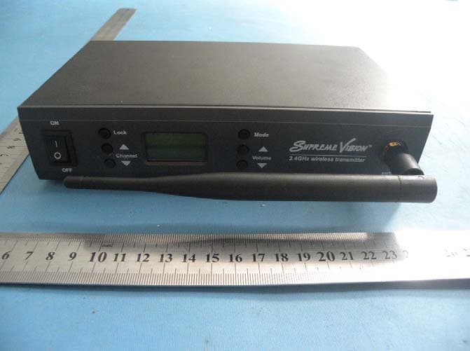
YQESV-301GT
Sep 19, 20102.4GHz Wireless Transmitter
Equipment Class
DXX - Part 15 Low Power Communication Device Transmitter