FCCID.CO- FCC ID Database
HomeCompaniesEquipment ClassesSearch

© 2026 FCC ID Database. All rights reserved.

AboutContactData sourced from FCC public records
  1. Home/
  2. Dipl.-Ing. H. Horstmann GmbH/
  3. YQVHHH002

YQVHHH002Wireless Transceiver Module

Dipl.-Ing. H. Horstmann GmbH
Wireless Transceiver Module - FCC ID YQVHHH002 - Dipl.-Ing. H. Horstmann GmbH
Click to zoom

Application Details

Equipment Class
DXX - Part 15 Low Power Communication Device Transmitter
Date of Grant
Sep 16, 2010
Application Purpose
Original Equipment
Date of Application
Sep 16, 2010
Equipment Note
Wireless Transceiver Module
Frequency Range
2400.50000000 - 2482.50000000
Company
Dipl.-Ing. H. Horstmann GmbH
Country
Germany

Documents & Files

Select a file to view

Users Manual

↗

Cover Letter(s)

↗
↗
↗
↗
↗

External Photos

↗

ID Label/Location Info

↗

Internal Photos

↗

Test Report

↗

Test Setup Photos

↗

Document Text

Text extracted from the exhibit documents filed with the FCC. Open a document above to read the original.

Users Manual

Dipl.-Ing. H. Horstmann GmbH Humboldtstraße 2 42579 Heiligenhaus www.horstmanngmbh.com Instructions for Use SMART CONTROLLER 14 September 2010 Dipl.-Ing. H. Horstmann GmbH Instructions for Use 2 SMART CONTROLLER CONTENTS Introduction .............................................................................................................................................. 3 Regulatory Information for the United States of America ........................................................................ 3 Regulatory Information for Canada ......................................................................................................... 4 SMART CONTROLLER SPECIFICATION .............................................................................................. 5 Product Photo & Label Information ......................................................................................................... 5 Integration Information ............................................................................................................................. 6 Instructions for Use Dipl.-Ing. H. Horstmann GmbH SMART RECEIVER 3 INTRODUCTION The SMART CONTROLLER is a wireless module intended to be integrated into other devices for monitoring overhead lines used for energy distribution. It transmits and receives wireless RF signals in the 2.4-2.5GHz band from Faulted Circuit Indicators decodes and relays them to the host device. This document covers features, specifications, regulatory information and recommendations for integration into a host device. REGULATORY INFORMATION FOR THE UNITED STATES OF AMERICA Compliance Statements Warning Installation, connection and commissioning of the SMART CONTROLLER must be carried out exclusively by a skilled/qualified electrician observing the applicable safety rules and regulations. Attention This device complies with Part 15 of the FCC Rules. Operation is subject to the following two conditions: (1) this device may not cause harmful interference, and (2) this device must accept any interference received, including interference that may cause undesired operation Warning Changes or modifications to the SMART CONTROLLER not expressly approved by Dipl.-Ing. H. Horstmann GmbH could void the user's authority to operate the equipment. The Smart Controller is approved under Part 15 of the FCC rules as a Modular Transmitter. The following statements provide information for the system integrator that integrates the SMART CONTROLLER into his own device. Attention If the SMART CONTROLLER’s FCC identification number is not visible when the module is installed inside another device, the product into which the SMART CONTROLLER is integrated must show a label, according to FCC requirements (§15.212), with the FCC ID assigned to the SMART CONTROLLER: Contains FCC ID: YQVHHH002 Attention The following statement must be included into the information for the end user: This device complies with Part 15 of the FCC Rules. Operation is subject to the following two conditions: (1) this device may not cause harmful interference, and (2) this device must accept any interference received, including interference that may cause undesired operation Dipl.-Ing. H. Horstmann GmbH Instructions for Use 4 SMART CONTROLLER REGULATORY INFORMATION FOR CANADA The SMART CONTROLLER is approved under Industry Canada documents as a Modular Transmitter. The following statements provide information for the system integrator that integrates the SMART CONTROLLER into his own device. Attention If the SMART CONTROLLER’s identification number is not visible when the module is installed inside another device, the product into which the SMART CONTROLLER is integrated must show a label, according to with the following statement: Contains IC: 9199A-HHH002 Attention The following statement must be included into the information for the end user: Operation is subject to the following two conditions: (1) this device may not cause harmful interference, and (2) this device must accept any interference received, including interference that may cause undesired operation This device has been designed to operate with the antennas listed below, and having a maximum gain of 2.5 dB. Antennas not included in this list or having a gain greater than 2.5 dB are strictly prohibited for use with this device. The required antenna impedance is 50 ohms. Antenna: Laird Technologies Mini-Nanoblade Instructions for Use Dipl.-Ing. H. Horstmann GmbH SMART RECEIVER 5 SMART CONTROLLER SPECIFICATION Electrical data: Radiated Frequency: 2.4 – 2.5 GHz Radiated Power: 0dBm Energy Supply 5V DC +/- 10 % / 60 mA max. Operating temperature: -40 °C... +85 °C Mechanical data: Size 94 mm x 50 mm x 15 mm Weight 50 g PRODUCT PHOTO & LABEL INFORMATION Label containing: - Product name - Horstmann part number - FCC ID - IC ID - Horstmann company logo and CE mark Dipl.-Ing. H. Horstmann GmbH Instructions for Use 6 SMART CONTROLLER INTEGRATION INFORMATION The module dimensions are shown below: The module should be fixed to the host device using 4 screws (diameter 3mm). There are no restrictions with respect to ground planes in the underneath or above the SMART CONTROLLER. The connector to the SMART CONTROLLER is a standard 2 x 6 Pin 2.0 mm SMT Male Header. Signal Description Signal Pin I/O Remark GND 4, 10 - Ground VCC 5, 7 - 5 V DC RESET 11 Input Active Low, 100K internal pull up TXD 6 Output serial data to Host RXD 8 Input serial data from Host NC 1, 2, 3, 9, 12 - not connected

Cover Letter(s)

ELEKTROTECHNISCHE GERÄTE UND ANLAGEN DIPL.-ING H. HORSTMANN GMBH 42579 HEILlGENHAUS • HUMBOLDTSTRASSE 2 • TELEFON +49 2056 976-0 • TELEFAX +49 2056 976-140 INTERNET: www.horstmanngmbh.com·E-MAlL:[email protected] H.Horstmann GmbH Humboldtstrasse 7 42579 Heiligenhaus 26.August 2010 T 0 whom it may concern Commercial Power of Attorney for type approval in several countries The company 71ayers AG has been contracted by H.Horstmann GmbH to obtain "Radio Type Approvals" for the following electronic component manufactured and/or released by H.Horstmann GmbH: -Smart Controller -Smart Navigator -Smart Receiver The following persons at 7 layers AG will be authorized: Mr. Bernhard Retka Mr. Holger Leutfeld Unless future correspondence from H. Horstmann GmbH directs otherwise, please extend your full cooperation to 7 layers regarding matters to the above mentioned products for the period beginning 2010 Aug 25 through end of the project date. Thank you .

External Photos

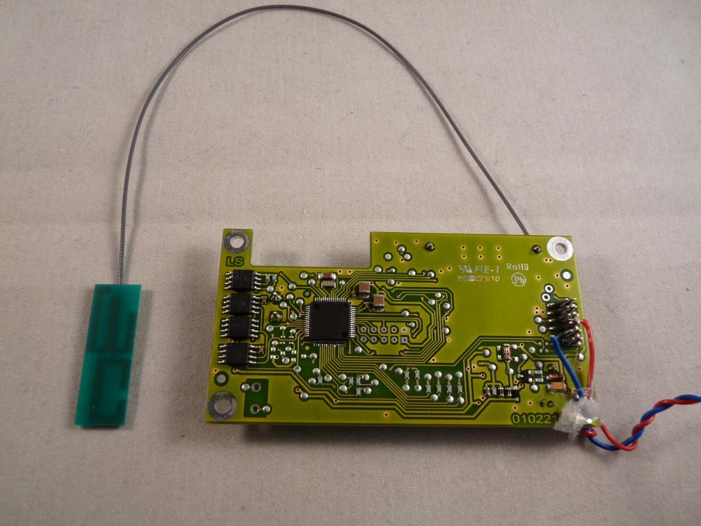
Annex I: Photo Report Test report reference: MDE_HORST_1001_FCCa Page 4 of 4 Photo 5: EUT (front side) Photo 6: EUT (rear side)

Test Report

7 layers AG Aufsichtsratsvorsitzenderh Registergerichth registered in: Borsigstrasse 11 Chairman of the Supervisory Board: Düsseldorf, HRB 44096 40880 Ratingen, Germany Markus Becker USt-IdNr h VAT No.: Phone: +49 (0) 2102 749 0 Vorstandh Board: DE 203159652 Fax: +49 (0) 2102 749 350 Dr. H.-J. Meckelburg TAX No. 147/5869/0385 www.7Layers.com Wilfried Klassmann FCC Measurement/Technical Report on Transceiver Module Smart Controller FCC ID: YQVHHH002 IC CN: 9199A-HHH002 Report Reference: MDE_HORST_1001_FCCa Test Laboratory: 7 layers AG Borsigstrasse 11 40880 Ratingen Germany email: [email protected] DGA-PL-192/99-02 Note: The following test results relate only to the devices specified in this document. This report shall not be reproduced in parts without the written approval of the testing laboratory. Test report Reference: MDE_HORST_1001_FCCa Page 2 of 34 Table of Contents 0 Summary 3 0.1 Technical Report Summary 3 0.2 Measurement Summary 4 1 Administrative Data 5 1.1 Testing Laboratory 5 1.2 Project Data 5 1.3 Applicant Data 5 1.4 Manufacturer Data 5 2 Test object Data 6 2.1 General EUT Description 6 2.2 EUT Main components 7 2.3 Ancillary Equipment 7 2.4 Auxiliary Equipment 7 2.5 EUT Setups 8 2.6 Operating Modes 8 2.7 Product labelling 8 3 Test Results 9 3.1 Conducted emissions (AC power line) 9 3.2 Occupied bandwidth 11 3.3 Peak power output 12 3.4 Spurious radiated emissions 13 4 Test Equipment 19 5 Photo Report 27 6 Setup Drawings 27 7 Annex measurement plots 28 7.1 AC Mains conducted 28 7.2 Occupied bandwidth 29 7.3 Peak power output 31 7.4 Verification of band edge emissions 33 Test report Reference: MDE_HORST_1001_FCCa Page 3 of 34 0 Summary 0.1 Technical Report Summary Type of Authorization Certification for an Intentional Radiator (Digital Transmission Systems DTS). Applicable FCC Rules Prepared in accordance with the requirements of FCC Rules and Regulations as listed in 47 CFR Ch.1 Parts 2 (10-1-09 Edition) and 15 (10-1-09 Edition). The following subparts are applicable to the results in this test report. Part 2, Subpart J - Equipment Authorization Procedures, Certification Part 15, Subpart C – Intentional Radiators § 15.201 Equipment authorization requirement § 15.207 Conducted limits § 15.209 Radiated emission limits; general requirements § 15.215 Additional provisions to the general radiated emission limitations. § 15.249 Operation within the bands 902-928 MHz, 2400-2483.5 MHz and 5725-5850 MHz Note: Additionally the following Public Notice was considered: "Measurement of radiated emissions at the edge of the band for a Part 15 RF Device" Publication Number KDB913591 Summary Test Results: The EUT complied with all performed tests as listed in chapter 0.2 Measurement Summary. Test report Reference: MDE_HORST_1001_FCCa Page 5 of 34 1 Administrative Data 1.1 Testing Laboratory Company Name: 7 Layers AG Address Borsigstr. 11 40880 Ratingen Germany This facility has been fully described in a report submitted to the FCC and accepted under the registration number 96716. The test facility is also accredited by the following accreditation organisation: - Deutscher Akkreditierungs Rat DAR-Registration no. DGA-PL-192/99-02 Responsible for Accreditation Scope: Dipl.-Ing. Bernhard Retka Dipl.-Ing. Robert Machulec Dipl.-Ing. Thomas Hoell Dipl.-Ing. Andreas Petz Report Template Version: 2010-09-03 1.2 Project Data Responsible for testing and report: Dipl.-Ing. Robert Machulec Date of Test(s): 2010-08-11 to 2010-09-15 Date of Report: 2010-09-15 1.3 Applicant Data Company Name: Dipl.-Ing. H. Horstmann GmbH Address: Humboldtstraße 2 D-42579 Heiligenhaus Germany Contact Person: Mr. Frank Langenberg 1.4 Manufacturer Data Company Name: please see applicant data Address: Contact Person: Test report Reference: MDE_HORST_1001_FCCa Page 6 of 34 2 Test object Data 2.1 General EUT Description Equipment under Test: Transceiver Module Type Designation: Smart Controller Kind of Device: (optional) Voltage Type: DC Voltage level: 5 V General product description: The Transceiver is operating in the 2.4 GHz ISM band at carrier frequencies 2400.5 and 2482.5 MHz. Modulation: MSK, Data Rate: 250 kbps Specific product description for the EUT: The Smart Controller is designed as a printed circuit board that integrates into a host application. The interface between both consists of a power supply and a serial port. The Smart Controller communicates over a bidirectional short-range radio link with up to 12 Smart Navigators (overhead fault circuit indicators). The Smart Navigators transmit measurement and status data to the Smart Controller in the event of an overhead line fault or within pre-defined periods to the Smart Controller. The Smart Controller temporarily stores this data and communicates it via the serial port to the host application. The EUT provides the following ports: Ports Enclosure Permanent antenna connector System connector incl. power supply The main components of the EUT are listed and described in Chapter 2.2. Test report Reference: MDE_HORST_1001_FCCa Page 7 of 34 2.2 EUT Main components Type, S/N, Short Descriptions etc. used in this Test Report Short Description Equipment under Test Type Designation Serial No. HW Status SW Status Date of Receipt EUT A (Code: UN010a01) Transceiver Module Smart Controller - B ID266 2010-08-11 Remark: EUT A is equipped with an external antenna (max. gain = 2.5 dBi). NOTE: The short description is used to simplify the identification of the EUT in this test report. 2.3 Ancillary Equipment For the purposes of this test report, ancillary equipment is defined as equipment which is used in conjunction with the EUT to provide operational and control features to the EUT. It is necessary to configure the system in a typical fashion, as a customer would normally use it. But nevertheless Ancillary Equipment can influence the test results. Short Description Equipment under Test Type Designation Serial no. HW Status SW Status FCC ID – – 2.4 Auxiliary Equipment For the purpos…

Text truncated - open the document above for the full version.

Test Setup Photos

Annex I: Photo Report Test report reference: MDE_HORST_1001_FCCa Date: 2010-09-03 Annex I: Photo Report Test report reference: MDE_HORST_1001_FCCa Page 2 of 4 1 Photo Report Photo 1: Test setup for conducted emissions (AC mains) Photo 2: Test setup for radiated measurements (Enclosure, below 30 MHz) Annex I: Photo Report Test report reference: MDE_HORST_1001_FCCa Page 3 of 4 Photo 3: Test setup for radiated measurements (Enclosure, 30 MHz to 1 GHz) Photo 4: Test setup for radiated measurements (Enclosure, above 1 GHz) Annex I: Photo Report Test report reference: MDE_HORST_1001_FCCa Page 4 of 4 Photo 5: EUT (front side) Photo 6: EUT (rear side)

Contact Information

Applicant

Frank Langenberg
[email protected]+49 2056 976Fax: +49 2056 976 144

Test Firm

7layers AGRobert Machulec
[email protected]49-2102-749-313Fax: 49-2102-749-350

Technical Specifications

#Rule PartsFrequency RangePower Output
115C2.40 GHz - 2.48 GHz-
Modular Type
Single Modular Approval
Confidentiality
Long Term
Grant Notes
End users may not be provided with the module installation instructions.

Other Applications from Dipl.-Ing. H. Horstmann GmbH
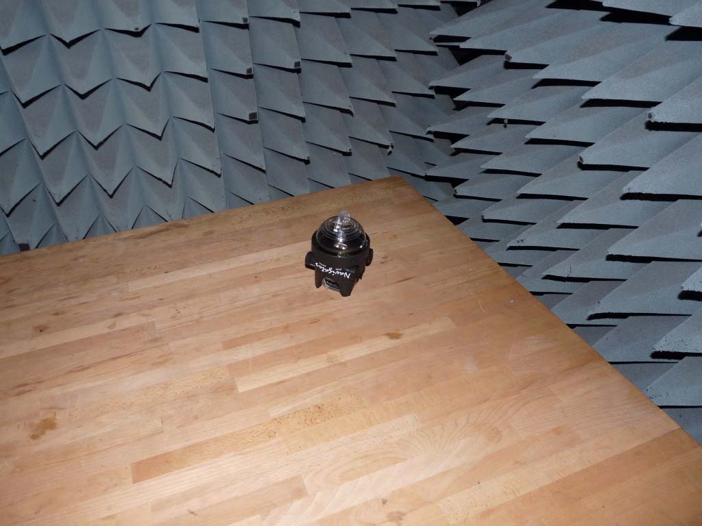
Smart Navigator - FCC ID YQVHHH001 - Dipl.-Ing. H. Horstmann GmbH
YQVHHH001

Smart Navigator

Nov 03, 2010

Equipment Class

DXX - Part 15 Low Power Communication Device Transmitter