YRADO-G1116USB Configurator
Inventory Systems GmbH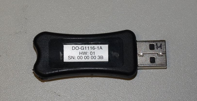
Click to zoom
Application Details
- Equipment Class
- DTS - Digital Transmission System
- Date of Grant
- Nov 07, 2010
- Application Purpose
- Original Equipment
- Date of Application
- Nov 07, 2010
- Equipment Note
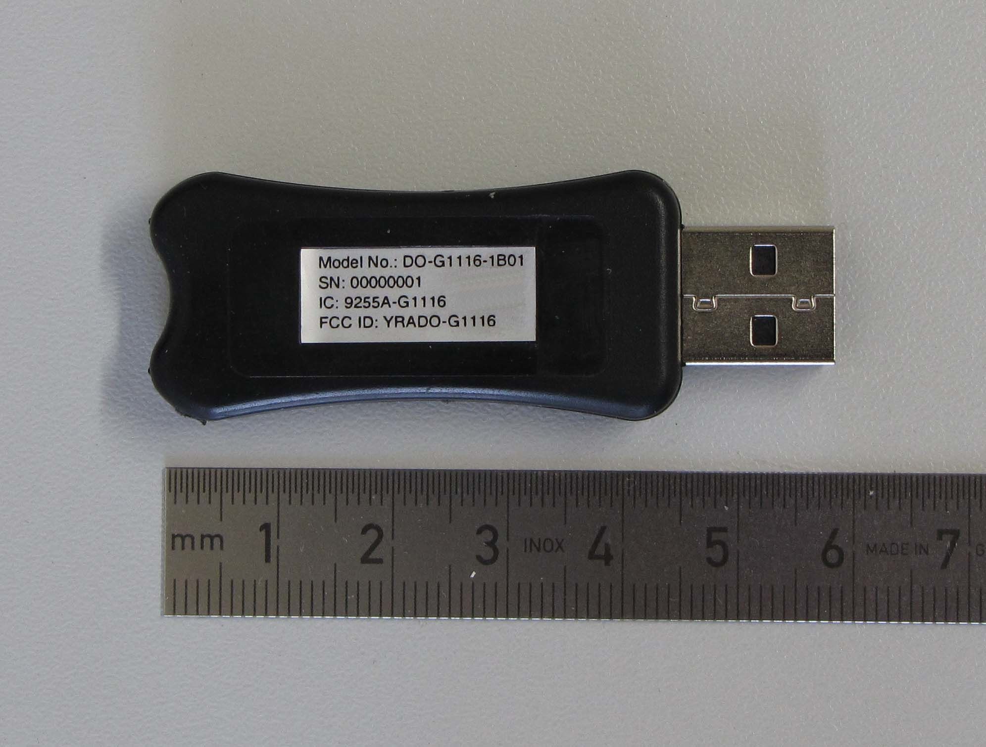
- USB Configurator
- Frequency Range
- 915.00000000 - 915.00000000
- Company
- Inventory Systems GmbH
- Country
- Germany
Documents & Files
Document Text
Text extracted from the exhibit documents filed with the FCC. Open a document above to read the original.
Users Manual
INSTRUCTION MANUAL Monitoring system for atypical removal of products Instruction_manual_monitoring_system_vers10.doc Page 2 of 44 Date: 28.10.2010 Version: 10 1. Data sheet Serial no. Serial no. of the central unit SN: The serial number (1) is listed on top of the sticker label on the back side of the board, directly after the word: “SN” Serial no. Serial no. of the expander module SN: The serial number (2) is listed on top of the sticker label on the back side of the board, directly after the word: “SN” Serial no. Serial no. of the USB-Stick SN: The serial number (3) is listed on the sticker label directly after the word: “SN” Serial no. Serial no. of the pager SN: After switching on the pager, the serial number is displayed for about two sec- onds. Alarms Factory-installed alarms: There are pre-set alarms plus a self-learning fea- ture to adjust alarm levels Location Location of the antenna: Location Location of the central unit: Instruction_manual_monitoring_system_vers10.doc Page 3 of 44 Date: 28.10.2010 Version: 10 Copyright © Any reproduction of the delivered software, of this instruction manual and the exploitation and publication of its contents are subject to our prior written consent. Any infringement will give rise to claims for damages. All rights reserved. These operating instructions describe the functions and the handling of the monitoring sys- tem. We tried to give a description as exactly as possible of the devices and of all the functions. We cannot guarantee the correctness and integrity of the contents of this document, even if we tried hard to do so. We would therefore be grateful at any time to let us have any sugges- tions for improvement or additional ideas. Trademarks and logos The use of a trademark or logo which is not mentioned in this document does not mean that it can be used without any restrictions. Instruction_manual_monitoring_system_vers10.doc Page 4 of 44 Date: 28.10.2010 Version: 10 TABLE OF CONTENTS 1. DATA SHEET .................................................................................................................... 2 2. INTRODUCTION ............................................................................................................... 6 2.1 Symbols used ............................................................................................................... 6 3. INTENDED USE ................................................................................................................ 7 4. SAFETY INSTRUCTIONS ................................................................................................. 8 5. TECHNICAL DATA ......................................................................................................... 10 6. SCOPE OF DELIVERY ................................................................................................... 11 7. DESCRIPTION ................................................................................................................ 13 7.1 Overview...................................................................................................................... 13 8. COMMISSIONING ........................................................................................................... 14 8.1 Installing the monitoring system .............................................................................. 14 8.1.1 Basic information ................................................................................................... 14 8.2 Mounting the central unit and the expander module .............................................. 15 8.3 Cabling the monitoring system ................................................................................. 16 8.4 Pager ........................................................................................................................... 19 8.5 Requirements.............................................................................................................. 20 8.6 Installation of the software IMCo PC Tool ................................................................ 21 9. OPERATION AND DESCRIPTION OF THE SOFTWARE .............................................. 24 9.1 Starting the software IMCo PC Tool and configuring the monitoring system ...... 24 9.1.1 General information ............................................................................................... 24 9.1.2 Starting the software IMCoPCTool ........................................................................ 25 9.2 Adjusting basic settings ............................................................................................ 26 9.2.1 Setting up the connection to the central unit ......................................................... 26 9.2.2 Integration of the connected components ............................................................. 26 9.2.3 Configuration of the expander modules (EXP) ...................................................... 27 9.3 Sending the settings to the central unit ................................................................... 31 9.4 Filling of the system ................................................................................................... 31 Instruction_manual_monitoring_system_vers10.doc Page 5 of 44 Date: 28.10.2010 Version: 10 9.5 Alarm display .............................................................................................................. 32 9.6 Operating modes ........................................................................................................ 33 9.7 Structure of the log file .............................................................................................. 34 9.8 Exit the software ......................................................................................................... 36 10. CLEANING ...................................................................................................................... 37 11. TROUBLE SHOOTI…
Text truncated - open the document above for the full version.
Cover Letter(s)
PHOENIX TEST LAB GmbH Konigswinkel 10 D-32825 Blom berg, Germany Gentlemen, Please be advised that Inventory Systems GmbH authorizes Mr. Marco Janker from EMV TESTHAUS GmbH to act on our behalf for application submittals for FCC Grants of Certification and Industry Canada to PHOENIX TEST LAB GmbH. We certify that we are not subject to denial of federal benefits, including FCC benefits, pursuant to Section 5301 of the Anti Drug Abuse Act of 1988, U.S.C. 862. Further, no party as defined in 47 CFR 1002(b) to the application is subject to the denial of Federal benefits, including FCC benefits. Thank ,///a// *2 Inventory€ystems GmbH tleerstreße 2, D-14052 Berlin T6l. +49(0)90-2000361 24 Fa(. +49(0)9G39788225 Name: Georg Hachmann -??/q/?a-rc
Cover Letter(s)
EMV Briefbogen 2008 ult 30.07.2008 10:39 Uhr Seite 1 Probedruck CMYCMMYCYCMYK Ersteller: U. Rodemeier Revision: 04 Erstelldatum: 03.08.01 Datum: 11.05.07 Seite 1 von 1 Request for Confidentiality PHOENIX TESTLAB GmbH Date: 2010-10-20 Product Certification Königswinkel 10 D 32825 Blomberg RE: Certification Application FCC ID: YRADO-G1116 Confidentiality Request Pursuant to Sections 0.457 and 0.459 of the Commission’s Rule, the applicant hereby requests confidential treatment of information accompanying this application as outlined below: • Block Diagram inside document “Block_Diagram_DO-G1116.pdf” • Schematics inside document “Schematics_DO-G1116.pdf” • Technical Description inside document “Technical_Description_DO- G1116.pdf” The above materials contain trade secrets and proprietary information not customarily released to the public. The public disclosure of these matters might be harmful to the applicant and provide unjustified benefits to its competitors. The applicant understands that pursuant to rule 0.457, disclosure of this application and all accompanying documentation will not be made before the date of the GRANT for this application. Thank you for your attention in this matter. Applicant’s Company address : Inventory Systems GmbH Heerstrasse 2 D-14052 Berlin GERMANY Signature : p.p. Job Title and Dept. : p.p. Marco Janker. EMV TESTHAUS GmbH
Cover Letter(s)
PHOENIX TEST-LAB GmbH Product Certification Königswinkel 10 D 32825 Blomberg To Whom lt May Concern: The FCC statement: "This device complies with Part 15 of the FCG Rules. Operation is subject to the following two conditions: (1) this device may not cause harmful interference, and (2) this device must accept any interference received, including interference that may cause undesired operation" ls not placed in the label of the equipment due to the following reasons: - Required text is already included in the user guide - After this equipment is assembled, user is not easily able to see FCC text. (Normally the equipment is assembled to "out-of-sight" i.e hide from user. The device name manual is the only end-user visible "part".) This statement is placed in a prominent location in the instruction manual. Position: CEO Company Adress; Heerstrasse 2 D-14052 Berlin Germany Tel.: +49 30 20036124 Fax.: +49 30 200036172 E-M ail : i nfo@ inventorv-svstems. de Thank you for your attention to this matter. Signatory Inventory Systems GmbH Heerstraße 2, D-140S2 Berlin rer. +49(0)@-2000961 24 : Ersteller: D Brandhorst Erstelldatum: 19,11 04 00 19 11 04 Revision Datum: Seite 1 von 1
External Photos
EMV TESTHAUS GmbH Gustav-Hertz-Straße 35 94315 Straubing Germany Revision: 1.01 Inventory Systems GmbH USB Configurator 100393-AU02+W03 Annex C Page 1 of 2 1 Annex C – EUT external pictures 1.1 List of Pictures Picture 2: EUT (front side) ................................................................................................. 2 Picture 1: EUT (back side) ................................................................................................. 2 EMV TESTHAUS GmbH Gustav-Hertz-Straße 35 94315 Straubing Germany Revision: 1.01 Inventory Systems GmbH USB Configurator 100393-AU02+W03 Annex C Page 2 of 2 Picture 1: EUT (front side) Picture 2: EUT (back side)
Internal Photos
EMV TESTHAUS GmbH Gustav-Hertz-Straße 35 94315 Straubing Germany Revision: 1.01 Inventory Systems GmbH USB Configurator 100393-AU02+W03 Annex B Page 1 of 2 1 Annex B – EUT internal pictures 1.1 List of Pictures Picture 1: PCB top side ..................................................................................................... 2 Picture 2: PCB bottom side ................................................................................................ 2 EMV TESTHAUS GmbH Gustav-Hertz-Straße 35 94315 Straubing Germany Revision: 1.01 Inventory Systems GmbH USB Configurator 100393-AU02+W03 Annex B Page 2 of 2 Picture 1: PCB top side Picture 2: PCB bottom side
Test Setup Photos
EMV TESTHAUS GmbH Gustav-Hertz-Straße 35 94315 Straubing Germany Revision: 1.01 Inventory Systems GmbH USB Configurator 100393-AU02+W03 Annex A Page 1 of 3 1 Annex A – Pictures during test 1.1 List of Pictures Picture 1: EUT test setup for radiated emission test .......................................................... 2 Picture 2: EUT test setup for radiated emission tests ........................................................ 2 Picture 3: Conducted emission test (front) ......................................................................... 3 Picture 4: Conducted emission test (rear).......................................................................... 3 EMV TESTHAUS GmbH Gustav-Hertz-Straße 35 94315 Straubing Germany Revision: 1.01 Inventory Systems GmbH USB Configurator 100393-AU02+W03 Annex A Page 2 of 3 Picture 1: EUT test setup for radiated emission test Picture 2: EUT test setup for radiated emission tests EMV TESTHAUS GmbH Gustav-Hertz-Straße 35 94315 Straubing Germany Revision: 1.01 Inventory Systems GmbH USB Configurator 100393-AU02+W03 Annex A Page 3 of 3 Picture 3: Conducted emission test (front) Picture 4: Conducted emission test (rear)
Contact Information
Applicant
Georg Hachmann
Test Firm
EMV Testhaus GmbHMr. Rainer Heller
Technical Specifications
| # | Rule Parts | Frequency Range | Power Output |
|---|---|---|---|
| 1 | 15C | 915 MHz - 915 MHz | 6.00 mW |
Other Applications from Inventory Systems GmbH
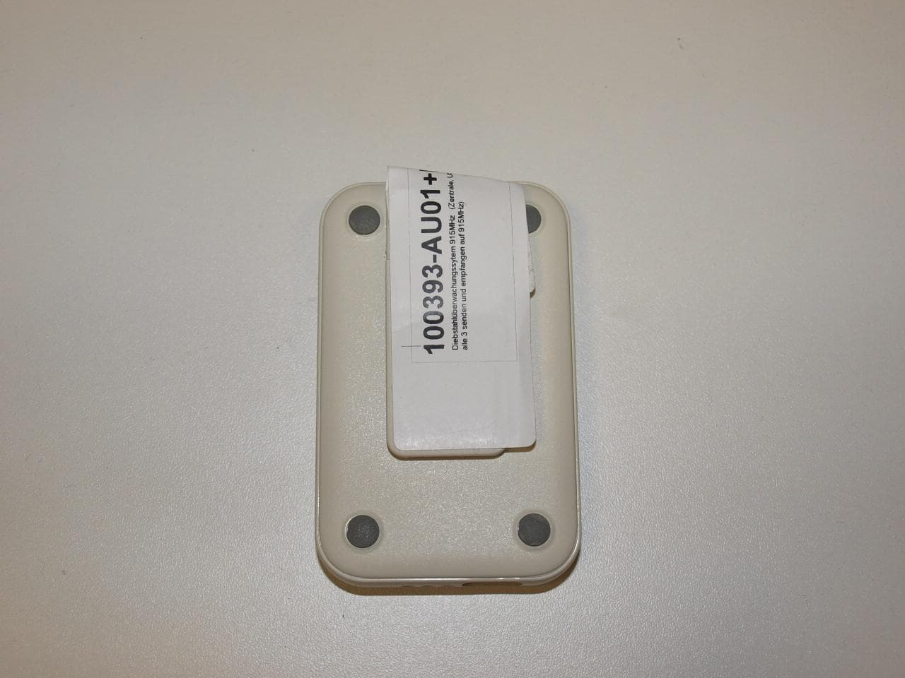
YRADO-G1164
Nov 07, 2010Pager
Equipment Class
DTS - Digital Transmission System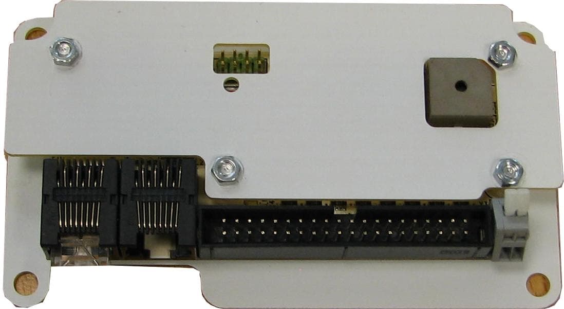
YRADO-B1829
Nov 07, 2010Base Unit
Equipment Class
DTS - Digital Transmission System