YRN-AGC-3220YFCAR AUDIO
Humax Co., Ltd.
Click to zoom
Application Details
- Equipment Class
- DSS - Part 15 Spread Spectrum Transmitter
- Date of Grant
- Aug 06, 2013
- Application Purpose
- Original Equipment
- Date of Application
- Aug 06, 2013
- Equipment Note
- CAR AUDIO
- Frequency Range
- 2402.00000000 - 2480.00000000
- Company
- Humax Co., Ltd.
- Country
- South Korea
Documents & Files
Document Text
Text extracted from the exhibit documents filed with the FCC. Open a document above to read the original.
Users Manual
Black plate (161,1) Model "AGC-3220YF: 2010/ 12/ 13 User’s Manual (AGC-3220YF) Type A (with MUTE button) SAA3476 1. MUTE button 2. FM·AM band select button 3. RPT (Repeat) button 4. MIX (Mix play) button 5. Radio memory buttons 6. DISP (Display) button 7. Quick search button 8. AUX button 9. CD EJECT button 10. CD button 11. VOLUME control knob/POWER ON/OFF button 12. TA (Traffic Announcement) button 13. Rewind button 14. Fast Forward button 15. SETUP button 16. BACK button 17. TUNE/MENU knob/ENTER button 18. PHONE button Black plate (162,1) Model "AGC-3220YF: 2010/ 12/ 13 FM-AM RADIO WITH COMPACT DISC (CD) PLAYER (for Europe, Russia and Ukraine) Type B (with DAY/NIGHT button) SAA3642 N04AE19 Anti-theft system (with personal code) N04AE1901 By using a personal 4-digit code known only to the vehicle owner, the possibility of the audio unit being stolen is effectively reduced, because without the code, the unit can not be activated. When used normally, the unit is unlocked and accessible in the usual way. If however, force is used to try and remove the unit, the anti-theft system activates and the unit locks. The only way it can be unlocked is by entering the personal code number known only by the owner. This code number cannot be altered and applies only to your vehicle. This code number is shown on a radio pass card. Ask your NISSAN dealer for the location of your radio pass card. WARNING: Keep the radio pass card in a safe place and refrain from keeping it in the vehicle. 1. DAY/NIGHT button 2. FM·AM band select button 3. RPT (Repeat) button 4. MIX (Mix play) button 5. Radio memory buttons 6. DISP (Display) button 7. Quick search button 8. AUX button 9. CD EJECT button 10. CD button 11. VOLUME control knob/POWER ON/OFF button 12. TA (Traffic Announcement) button 13. Rewind button 14. Fast Forward button 15. SETUP button 16. BACK button 17. TUNE/MENU knob/ENTER button 18. PHONE button Contact your NISSAN dealer if you lose the radio pass card or forget the code number of your radio. Unlocking the unit: N04AE190101 CAUTION: Read this section very carefully. It is important that the instructions are fol- lowed precisely. Black plate (163,1) Model "AGC-3220YF: 2010/ 12/ 13 If the battery supply to the vehicle is interrupted by accident for some reason, the unit will lock. To unlock the unit, proceed as follows: 1. Turn the ignition switch to the “ACC” or “ON” position. 2. Turn on the audio unit by pushing the POWER ON/OFF button. 3. Radio Code is displayed along with four numerical zero digits. 4. Push preset button * 1 the number of times corresponding with the first digit of the radio code. For example, if the radio code is 5169: for the first digit, “5”, push the preset button * 1 five times. 5. The second, third, and fourth digits of the radio code must be entered, in the same way, only now using preset buttons * 2 , * 3 , and * 4 . For example, push * 2 once, * 3 six times, and * 4 nine times. 6. Push and hold preset button * 6 to confirm the code. If you entered the code correctly the unit will switch on. 7. If the code is entered incorrectly a notifica- tion message (INCORRECT PIN) and the number of attempts left (REMAINING TRIES: XX) will be shown. After reading the message, push the ENTER button to return to the entry screen and enter the correct radio code. — If the wrong code is entered after the third attempt, the audio unit will lock for 60 minutes. The display will show a count down timer from 60 to 0 (minutes). After 60 minutes enter the correct radio code. — If the wrong code is entered after eight sets of three entries, th e audio unit will lock permanently. Contact a NISSAN dealer for further details. Audio main operation N04AE1902 The audio system operates when the ignition switch is in the “ACC” or “ON” position. POWER ON/OFF button: N04AE190201 To turn on the audio system, push the POWER ON/OFF button. ● The system will turn on in the mode, (radio or CD) which was used immediately before the system was turned off. ● If there is no CD loaded, the radio will be turned on. To turn off the audio system, push the POWER ON/OFF button. Volume control: N04AE190202 To control the volume, turn the VOLUME control dial. Turn the VOLUME control dial clockwise to make the sound louder. Turn the VOLUME control dial counterclockwise to make the sound quieter. SETUP button: N04AE190217 To configure Audio, Clock, Bluetooth, Language or Scroll direction settings, perform the following procedure: 1. Push the SETUP button. 2. Push the ENTER button. 3. Turn the TUNE/MENU knob clockwise or counterclockwise, the display will appear in the following order: Audio Û Clock Û Bluetooth Û Language Û Scroll Direction After the desired levels have been set, push either the BACK button repeatedly, the SETUP button, or wait for 8 seconds without pushing any buttons to exit the menu screen. Audio adjustments: N04AE190207 Push the SETUP button to enter the setup menu screen then select Audio. Each time the ENTER button is pushed, the mode will change as follows: Bass ? Treble ? Balance ? Fade ? AUX VOL ? SPD VOL ? Audio (setup menu screen) ? Bass Turn the TUNE/MENU knob clockwise or counterclockwise to adjust the following items and push ENTER to confirm. Black plate (164,1) Model "AGC-3220YF: 2010/ 12/ 13 Bass control: Turn the TUNE/MENU knob, the mode will change as follows: Language setting: N04AE190219 Use this control to enhance or attenuate bass response sound. Treble control: Use this control to enhance or attenuate the treble. Balance control: Use this control to adjust the balance of the volume between the left and right speakers. Fade (Fader) control: Use this control to adjust the balance of the volume between the front and rear (if equipped) speakers. AUX VOL (Auxiliary volume) control: Use this control to adjust the volume output from the auxiliary source. SPD VOL (Speed volume) control: This mode controls the volume output from the speakers automatically in relation to vehicle speed. Adjusti…
Text truncated - open the document above for the full version.
Cover Letter(s)
DAEWOOIS 7F NamkwangCentlexBldg., 440-4, Cheongcheon-dong, Bupyeong-gu, Incheon, Korea Date: August 02, 2013 Timco Engineering, Inc. 849 N.W. State Road 45 P.O. Box 370 Newberry, Florida 32669 USA LETTER OF AUTHORIZATION We, the undersigned, hereby authorize Harvey Sung of DIGITAL EMC CO., LTD. to act on our behalf in all manners relating to application for equipment authorization for FCC ID: YRN-AGC-3220YF including signing of all documents relating to these matters. Any and all acts carried out by Harvey Sung of DIGITAL EMC CO., LTD. on our behalf shall have the same affect as acts of our own. This authorization is valid until further written notice from DAEWOOIS Sincerely, Jungjin Hong Research Engineer
Cover Letter(s)
DAEWOOIS 7F NamkwangCentlexBldg., 440-4, Cheongcheon-dong, Bupyeong-gu, Incheon, Korea Date: August 02, 2013 Timco Engineering, Inc. 849 N.W. State Road 45 P.O. Box 370 Newberry, Florida 32669 USA RE: Request of Confidentiality for FCCID: YRN-AGC-3220YF To Whom It may Concern: Pursuant to Sections 0.457 and 0.459 of the Commission`s Rules(CFR 47), and Section 552 (b) (4) of the Freedom of Information Act, DAEWOOIS hereby requests confidentiality and treatment of certain information accompanying this application. The materials contain trade secrets and proprietary information not customarily released to the public. The public disclosure of these matters might be harmful to the Applicant and provide unjustified benefits to its competitors. We are also hereby request Short-Term Confidentiality for 180 days after the grant as outlined in Public Notice DA 04-1705. This provision will give DAEWOOIS temporary confidentiality of commercially sensitive information prior to product release. The requested permanent and Short-Term Confidential exhibits are listed as follows: PERMANENT & SHORT-TERM CONFIDENTIAL LIST Exhibit Description PERMANENT 1 Block Diagram 2 Schematics 3 Operational Description 4 Part Lists SHORT-TERM 5 External Photos 6 Internal Photos 7 Test-Setup Photos 8 User Manual The Applicant understands that pursuant to Rule 0.457, disclosure of this application and all accompanying documentations, where applicable, will not be public before the date of the Grant for this application. Sincerely, Jungjin Hong Research Engineer
Cover Letter(s)
DAEWOOIS 7F NamkwangCentlexBldg., 440-4, Cheongcheon-dong, Bupyeong-gu, Incheon, Korea Date: August 02, 2013 Timco Engineering, Inc. 849 N.W. State Road 45 P.O. Box 370 Newberry, Florida 32669 USA DECLARATION FOR ADDITIONAL FREQUENCY HOPPING REQUIREMENTS To whom it may concern: We hereby declare that the Bluetooth of YRN-AGC-3220YF meet following FCC requirements of the Section 15.247(a)(1) : 1. The hopping sequence is pseudorandom. 2. All channels are used equally on average. 3. The receiver input bandwidth approximately equal the transmit bandwidth. 4. The receiver hop in sequence with the transmit signal. Sincerely, Jungjin Hong Research Engineer
External Photos
FCCID: YRN-AGC-3220YF Copyright Ⓒ 2013, Digital EMC Co., Ltd. View 1 FCCID: YRN-AGC-3220YF Copyright Ⓒ 2013, Digital EMC Co., Ltd. View 2 FCCID: YRN-AGC-3220YF Copyright Ⓒ 2013, Digital EMC Co., Ltd. View 3
ID Label/Location Info
FCC ID: YRN-AGC-3220YF Copyright Ⓒ 2013, Digital EMC Co., Ltd. SAMPLE LABEL & LOCATION LABELLING REQUIREMENTS The Label shown shall be permanently affixed at a conspicuous location on the device and be readily visible to the user at the time of purchase Label locate Top side This device complies with Part 15 of the FCC Rules. Operation is subject to the following two conditions: 1) This device may not cause harmful interference, and 2) This device must accept any interference received, including interference that may cause undesired operation of the device. - The FCC label shown is representative of the label that will appear on the radio when in production. Other information may also be included on this label.
Internal Photos
FCCID: YRN-AGC-3220YF Copyright Ⓒ 2013, Digital EMC Co., Ltd. Page1 / 5 View 1 FCCID: YRN-AGC-3220YF Copyright Ⓒ 2013, Digital EMC Co., Ltd. Page2 / 5 View 2 FCCID: YRN-AGC-3220YF Copyright Ⓒ 2013, Digital EMC Co., Ltd. Page3 / 5 View 3 FCCID: YRN-AGC-3220YF Copyright Ⓒ 2013, Digital EMC Co., Ltd. Page4 / 5 View 4 FCCID: YRN-AGC-3220YF Copyright Ⓒ 2013, Digital EMC Co., Ltd. Page5 / 5 Antenna
RF Exposure Info
-~ - - The MPE calculation for this exposure is shown below. The peak radiated output power (EIRP) is calculated as follows: ▪=+- =+ = - ▪S=- =X = mW/cm 2 FCCID: YRN-AGC-3220YF MPE Calculations Frequency range :2402MHz2480MHz 2.26dBm 2.80dBi Maximum RF output power : Maximum antenna peak gain : The EUT will only be used with a separation of 20 centimeters or greater between the antenna and the user. EIRPPGNote 2.26dBm2.80dBiP = Power input to the antenna(dBm) 5.06dBmG = Power gain of the antenna(dBi) Power density at the specific separation P G / ( 4 R 2 π ) Note 1.68 1.905 / ( 4 X 20 2 X π )S = Maximum power dencity(mW/cm 2 ) 0.00064 mW/cm 2 P = Power input to the antenna(mW) G = Numeric power gain of the antenna R = Distance to the center of the radiation of the antenna(20cm) Conclusion : N/A (The EIRP is below the limit.) The maximum permissible exposure(MPE) of the general population/Uncontrolled for this device is 1.61 TRF-RF-206(00)100216
Test Report
DEMC1307-02145 FCC ID: YRN-AGC-3220YF Report No.: DRTFCC1308-0746 TRF-RF-212(00)101214 Page 2 / 68 Copyright ○ C 2013, Digital EMC Co., Ltd. Test Report Version Test Report No. Date Description DRTFCC1308-0746 Aug. 07, 2013 Initial issue DEMC1307-02145 FCC ID: YRN-AGC-3220YF Report No.: DRTFCC1308-0746 TRF-RF-212(00)101214 Page 3 / 68 Copyright ○ C 2013, Digital EMC Co., Ltd. Table of Contents 1. General Information ............................................................................................................... 5 1.1 Testing Laboratory ......................................................................................... 5 1.2 Details of Applicant ........................................................................................ 5 1.3 Description of EUT ......................................................................................... 5 1.4. Declaration by the manufacturer .................................................................... 5 1.5. Information about the FHSS characteristics: ................................................ 6 1.6. Test Equipment List ........................................................................................ 7 1.7. Summary of Test Results ................................................................................ 8 1.8 Conclusion of worst-case and operation mode .............................................. 9 2. Transmitter Radiated Spurious Emissions and Conducted Spurious Emission .......... 10 2.1. Test Setup ...................................................................................................... 10 2.2. Limit ................................................................................................................ 10 2.3. Test Procedures............................................................................................. 11 2.3.1. Test Procedures for Radiated Spurious Emissions................................ 11 2.3.2. Test Procedures for Conducted Spurious Emissions ............................ 11 2.4. Test Results ................................................................................................... 12 2.4.1. Radiated Emission .................................................................................... 12 2.4.2. Conducted Spurious Emissions .............................................................. 15 3. Carrier Frequency Separation............................................................................................. 33 3.1. Test Setup..................................................................................................... 33 3.2. Limit ................................................................................................................ 33 4. Number of Hopping Frequencies ....................................................................................... 38 4.1. Test Setup..................................................................................................... 38 4.2. Limit ................................................................................................................ 38 5. 20dBc BW .............................................................................................................................. 47 5.1. Test Setup ...................................................................................................... 47 5.2. Limit ................................................................................................................ 47 5.3. Test Procedure .............................................................................................. 47 5.4. Test Results ................................................................................................... 47 6. Time of Occupancy (Dwell Time) ........................................................................................ 53 6.1. Test Setup ...................................................................................................... 53 6.2. Limit ................................................................................................................ 53 6.3. Test Procedure .............................................................................................. 53 6.4. Test Results ................................................................................................... 53 7. Maximum Peak Output Power Measurement .................................................................... 58 7.1. Test Setup ...................................................................................................... 58 7.2. Limit ................................................................................................................ 58 7.3. Test Procedure ............................................................................................... 58 7.4. Test Results ................................................................................................... 59 8. Transmitter AC Power Line Conducted Emission ............................................................ 65 8.1. Test Setup ...................................................................................................... 65 DEMC1307-02145 FCC ID: YRN-AGC-3220YF Report No.: DRTFCC1308-0746 TRF-RF-212(00)101214 Page 4 / 68 Copyright ○ C 2013, Digital EMC Co., Ltd. 8.2. Limit ................................................................................................................ 65 8.3. Test Procedures ............................................................................................. 65 8.4. Test Results : N/A .......................................................................................... 65 9. Antenna Requirement .......................................................................................................... 66 10. Occupied Bandwidth(99%) ................................................................................................ 67 APPENDIX I ................…
Text truncated - open the document above for the full version.
Test Setup Photos
FCC ID: YRN-AGC-3220YF Copyright Ⓒ 2013, Digital EMC Co., Ltd. Test Setup Photo of Radiated Measurement (Below 30MHz) FCC ID: YRN-AGC-3220YF Copyright Ⓒ 2013, Digital EMC Co., Ltd. Test Setup Photo of Radiated Measurement (Below 1GHz) FCC ID: YRN-AGC-3220YF Copyright Ⓒ 2013, Digital EMC Co., Ltd. Test Setup Photo of Radiated Measurement (Above ~ 1GHz)
Contact Information
Applicant
Inseok Seo
Test Firm
DT&C Co.,Changho Lee
Technical Specifications
| # | Rule Parts | Frequency Range | Power Output |
|---|---|---|---|
| 1 | 15C | 2.40 GHz - 2.48 GHz | 1.70 mW |
Other Applications from Humax Co., Ltd.
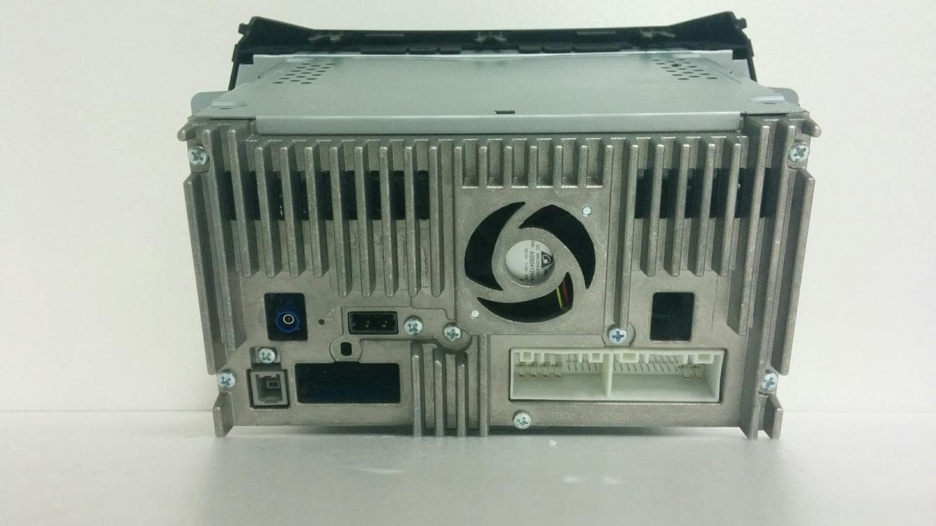
YRN-HAMT2001
Jun 07, 2015Car Audio
Equipment Class
DSS - Part 15 Spread Spectrum Transmitter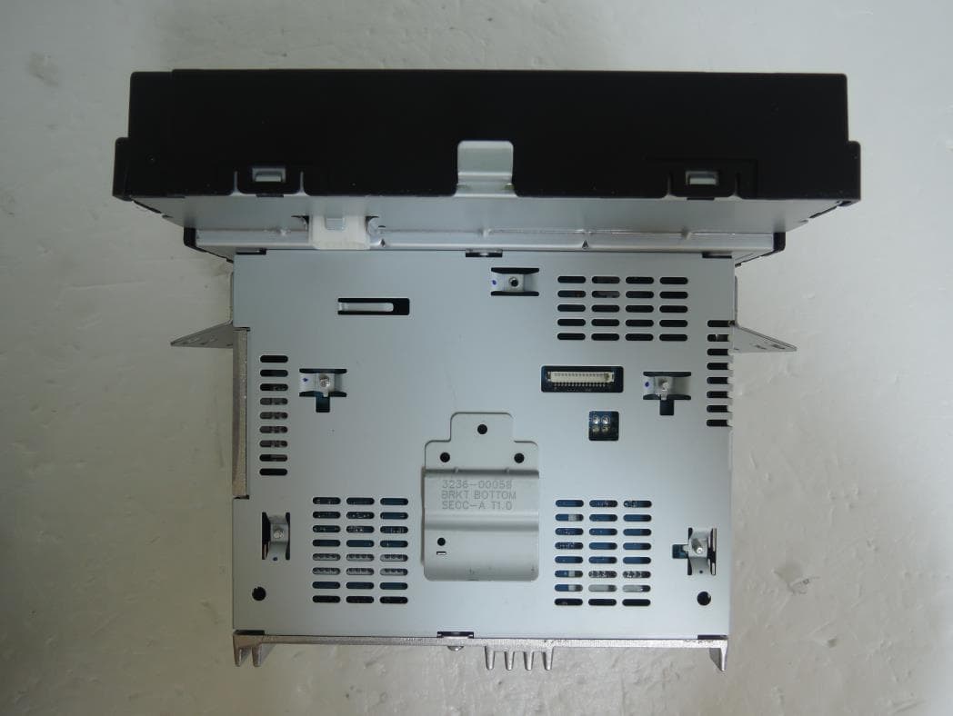
YRN-HAMT2002
Feb 12, 2015Car Audio
Equipment Class
DSS - Part 15 Spread Spectrum Transmitter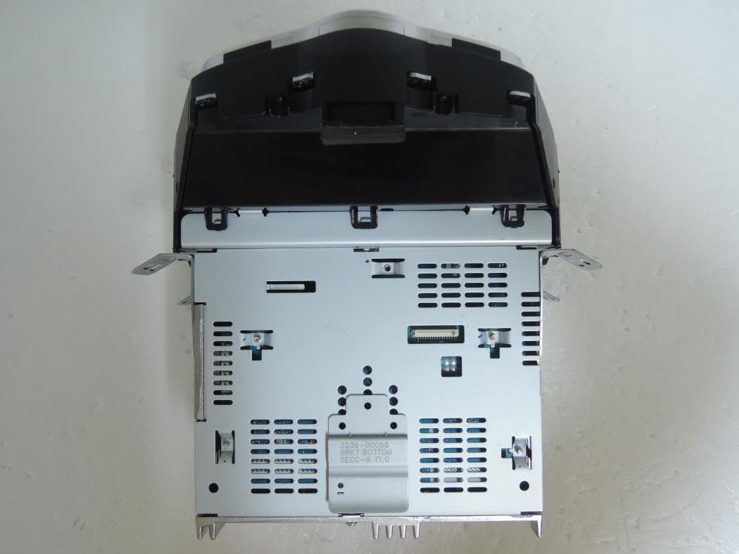
YRN-HAMT2003
Feb 09, 2015Car Audio
Equipment Class
DSS - Part 15 Spread Spectrum Transmitter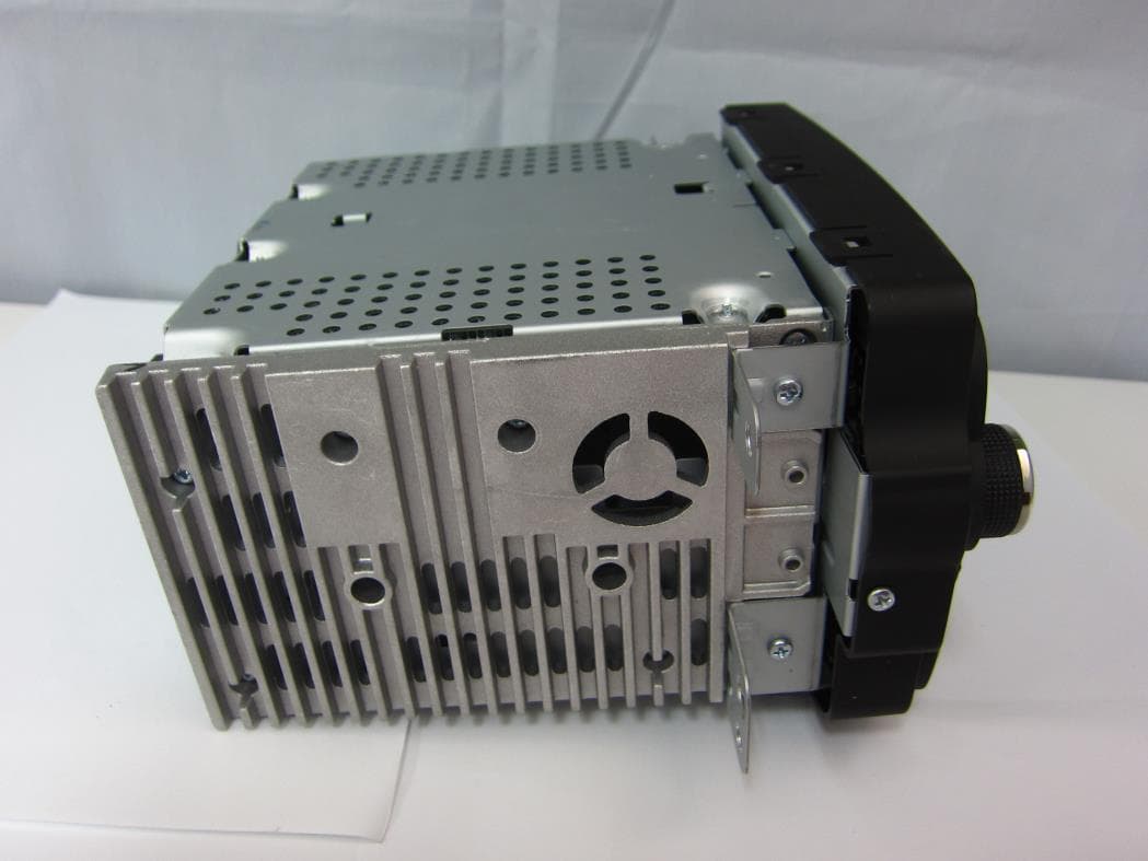
YRN-DWGM1004
Dec 26, 2013CAR AUDIO
Equipment Class
DSS - Part 15 Spread Spectrum Transmitter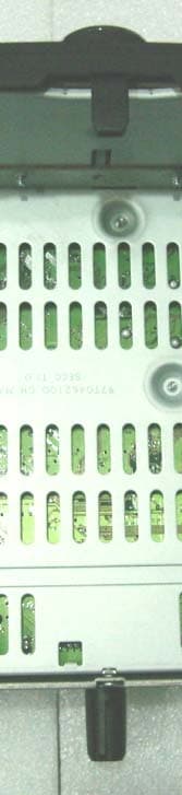
YRN-AGC-0060RF
Nov 14, 2010Car audio(Bluetooth)
Equipment Class
DSS - Part 15 Spread Spectrum Transmitter