YS9-PD124Rubata Bluetooth Keyboard Case
PADACS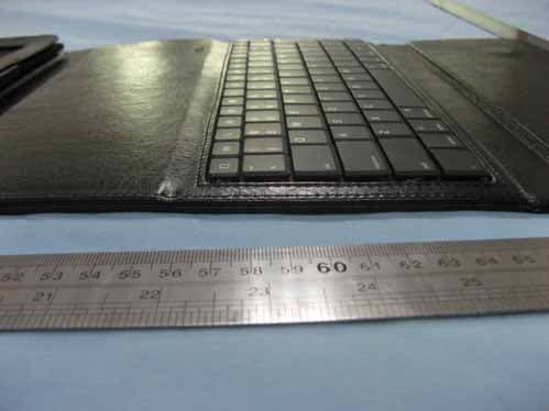
Click to zoom
Application Details
- Equipment Class
- DSS - Part 15 Spread Spectrum Transmitter
- Date of Grant
- Nov 02, 2010
- Application Purpose
- Original Equipment
- Date of Application
- Nov 02, 2010
- Equipment Note
- Rubata Bluetooth Keyboard Case
- Frequency Range
- 2402.00000000 - 2480.00000000
- Company
- PADACS
- Country
- Australia
Documents & Files
Document Text
Text extracted from the exhibit documents filed with the FCC. Open a document above to read the original.
Block Diagram
LS2042KM MODULE BLOCK DIAGRAM
Cover Letter(s)
PADACS Date: October 28, 2010 FCC ID:YS9-PD124 Dear Sir, I hereby have entrusted the following person to be a proxy regarding application for Type Certification. Attestation of Global Compliance Co., Ltd. Address: 1F., No.2 Building, Huafeng No.1 Technical Industrial Park, Sanwei, Xixiang, Baoan District, Shenzhen Name: Eason ZHAO Job Title: EMC Engineer Email: [email protected] I am therefore responsible for the contents of the application. Model Name of the specified radio equipment: FCC ID: YS9-PD124 Product Name: Rubata Bluetooth Keyboard Case Signature________ ___________ FCC grantee contact person information. Name/Title: Raaj Menon (CEO) Company Name: PADACS Address: 19, Aldenhoven Rd, Lonsdale, SA 5160, Australia TEL: +61 8 8186 1800 FAX: +61 8 8186 5211
External Photos
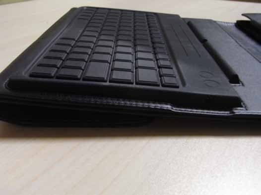
TOP VIEW OF SAMPLE BACK VIEW OF SAMPLE OPEN VIEW OF SAMPLE LEFT VIEW OF SAMPLE RIGHT VIEW OF SAMPLE
ID Label/Location Info
FCC ID Label Location
Internal Photos
INTERNAL PHOTO OF SAMPLE – 1 INTERNAL PHOTO OF SAMPLE – 2 INTERNAL PHOTO OF SAMPLE – 3
Operational Description
Operational description Bluetooth frequency 2402‐2480MHz Bluetooth version 2.0 Modulation GFSK Charging Voltage 110‐240V Operation Voltage 4.2V Charging period 4 hours Duration of charged battery 45 days Weight 478g Transmitter Power 0.0017W RF IC BCM2042 Crystal 24MHz 1.Frequency Range of a Bluetooth Device The maximum frequency of the device is 2402MHz - 2480 MHz. This is according the Bluetooth Core Specification V 2.0 2. Co-Ordination of the Hopping Sequence in Data Mode to Avoid Simultaneous Occupancy by Multiple Transmitters Bluetooth units, which want to communicate with other units, must be organized in a structure called piconet. This piconet consist of maximum 8 Bluetooth units. One unit is the master the other seven are the slaves. The master co-ordinates frequency occupation in this piconet for all units. As the master hop sequence is derived from it's BD address which is unique for every Bluetooth device, additional masters intending to establish new piconets will always use different hop sequences. 3. Example of a Hopping Sequence in Data Mode: Example of a 79 hopping sequence in data mode: 40, 21, 44, 23, 42, 53, 46, 55, 48, 33, 52, 35, 50, 65, 54, 67, 56, 37, 60, 39, 58, 69, 62, 71, 64, 25, 68, 27, 66, 57, 70, 59, 72, 29, 76, 31, 74, 61, 78, 63, 01, 41, 05, 43, 03, 73, 07, 75, 09, 45, 13, 47, 11, 77, 15, 00, 64, 49, 66, 53, 68, 02, 70, 06, 01, 51, 03, 55, 05, 04 4. Equally Average Use of Frequencies in Data Mode and Short Transmissions The generation of the hopping sequence in connection mode depends essentially on two input values: 1. LAP/UAP of the master of the connection 2. Internal master clock. The LAP (lower address part) is the 24 LSB's of the 48 BD-ADDRESS. The BD ADDRESS is an unambiguous number of every Bluetooth unit. The UAP (upper address part) are the 24 MSB's of the 48 BD-ADDRESS. The internal clock of a Bluetooth unit is derived from a free running clock, which is never adjusted and is never turned off. For synchronization with other units, only the offsets are used. It has no relation to the time of the day. Its resolution is at least half the RX/TX slot length of 312.5IJs. The clock has a cycle of about one day (23h30). In most case it is implemented as a 28-bit counter. For the deriving of the hopping sequence the entire LAP (24 bits), 4 LSB's (4 bits) (Input 1) and the 27 MSB's of the clock (Input 2) are used. With this input values different mathematical procedures (permutations, additions, XOR-operations) are performed to generate the sequence. This will be done at the beginning of every new transmission. Regarding short transmissions, the Bluetooth system has the following behavior: The first connection between the two devices is established, a hopping sequence is generated. For transmitting the wanted data, the complete hopping sequence is not used and the connection ends. The second connection will be established. A new hopping sequence is generated. Due to the fact that the Bluetooth clock has a different value, because the period between the two transmission is longer (and it cannot be shorter) than the minimum resolution of the clock (312.5 ms). The hopping sequence will always differ from the first one. 5. Receiver Input Bandwidth, Synchronization and Repeated Single or Multiple Packets The input bandwidth of the receiver is 1 MHz. In every connection, one Bluetooth device is the master and the other one is the slave. The master determines the hopping sequence (see section 5). The slave follows this sequence. Both devices shift between RX and TX Bluetooth Regulatory Information time slot according to the clock of the master. Additionally the type of connection (e.g. single or multi-slot packet) is set up at the beginning of the connection. The master adapts its hopping frequency and its TX/RX timing is according to the packet type of the connection. Also, the slave of the connection uses these settings. Repeating of a packet has no influence on the hopping sequence. The hopping sequence generated by the master of the connection will be followed in any case. That means, a repeated packet will not be send on the same frequency, it is send on the next frequency of the hopping sequence. 6. Dwell Time in Data Mode The dwell time of 0.3797s within a 30 seconds period in data mode is independent from the packet type (packet length). The calculation for a 30 seconds period is as follows: Dwell time = time slot length * hop rate / number of hopping channels *30s Example for a DH1 packet (with a maximum length of one time slot) Dwell time = 625 IJs * 1600 1/s /79 * 30s = 0.3797s (in a 30s period) For multi-slot packet the hopping is reduced according to the length of the packet. Example for a DH5 packet (with a maximum length of five time slots) Dwell time = 5 * 625 ms * 1600 * 1/5 *1/s / 79 * 30s = 0.3797s (in a 30s period) This is according the Bluetooth Core Specification V 2.0 for all Bluetooth devices. Therefore, all Bluetooth devices comply with the FCC dwell time requirement in the GSM mode. This was checked during the Bluetooth Qualification tests. The Dwell time in hybrid mode is measured and stated in the test report. 7. Channel Separation in Hybrid Mode The nominal channel spacing of the Bluetooth system is 1 MHz independent of the operating mode. The maximum “initial carrier frequency tolerance” which is allowed for Bluetooth is fcenter = 75 kHz. This was checked during the Bluetooth Qualification tests (Test Case: TRM/CA/07-E) for three frequencies (2402MHz, 2441MHz, 2480 MHz). 8. Derivation and Examples for a Hopping Sequence in Hybrid Mode For the generation of the inquiry and page hop sequences the same procedures as described for the data mode are used (see section 5), but this time with different input vectors: • For the inquiry hop sequence, a predefined fixed address is always used. This result in the same 32 frequencies used by all devices doing an inquiry but every time with a different start frequency and phase in this sequence. …
Text truncated - open the document above for the full version.
Test Report
FCC Test Report Report No.: AGC11581010SZ02F1 TEST NAME : FCC Part 15 FCC ID : YS9‐PD124 PRODUCT DESIGNATION : Rubata Bluetooth Keyboard Case BRAND NAME : PADACS TEST MODEL NAME : PD124 CLIENT : PADACS DATE OF ISSUE : Oct.13, 2010 STANDARD(S) : FCC Part 15 Rules Attestation of Global Compliance Co., Ltd. CAUTION: This report shall not be reproduced except in full without the written permission of the test laboratory and shall not be quoted out of context. Report No.: AGC11581010SZ02F1 Page 1 of 62 VERIFICATION OF COMPLIANCE Applicant: PADACS Address 19, Aldenhoven Rd, Lonsdale, SA 5160, Australia Manufacturer Name: FLAGSHIP INDUSTRIAL DESIGN CO., LTD Address: A-302.Shennan Garden, Kexing Road, Nanshan District, Shenzhen, China Product Description: Rubata Bluetooth Keyboard Case Brand Name: PADACS Model Number: PD124 FCC ID YS9-PD124 Report Number: AGC11581010SZ02F1 Date of Test: Oct. 01, 2010 to Oct.13, 2010 WE HEREBY CERTIFY THAT: The above equipment was tested by Attestation of Global Compliance Co., Ltd. The test data, data evaluation, test procedures, and equipment configurations shown in this report were made in accordance with the procedures given in ANSI C63.4 (2003) and the energy emitted by the sample EUT tested as described in this report is in compliance with radiated emission limits of FCC Rules Part 15.247. Checked By: Jekey Zhang Oct.13, 2010 Authorized By King Zhang Oct.13, 2010 Report No.: AGC11581010SZ02F1 Page 2 of 62 TABLE OF CONTENTS 1. GENERAL INFORMATION ............................................................................................................ 4 1.1 PRODUCT DESCRIPTION .................................................................................................................... 4 1.2 TABLE OF CARRIER FREQUENCYS ................................................................................................ 4 1.3 RELATED SUBMITTAL(S) / GRANT (S) ............................................................................................ 4 1.4 TEST METHODOLOGY .......................................................................................................................... 4 1.5 TEST FACILITY ....................................................................................................................................... 5 1.6 SPECIAL ACCESSORIES ..................................................................................................................... 5 1.7 EQUIPMENT MODIFICATIONS ............................................................................................................ 5 2. SYSTEM TEST CONFIGURATION ............................................................................................... 6 2.1 CONFIGURATION OF TESTED SYSTEM .......................................................................................... 6 2.2 EQUIPMENT USED IN TESTED SYSTEM ......................................................................................... 6 3. SUMMARY OF TEST RESULTS ................................................................................................... 7 4. DESCRIPTION OF TEST MODES ................................................................................................ 7 5. CONDUCTION EMISSIONS ........................................................................................................... 8 5.1 MEASUREMENT PROCEDURE: ......................................................................................................... 8 5.2 TEST SET-UP (BLOCK DIAGRAM OF CONFIGURATION) ........................................................... 8 5.3 MEASUREMENT EQUIPMENT USED ................................................................................................ 8 5.4 LIMITS AND MEASUREMENT RESULT ............................................................................................ 9 MEASURING INSTRUMENT AND SETTING .................................................................................. 9 The following table is the setting of receiver. ............................................................................. 9 TEST RESULT AT CHARGE MODE ......................................................................................................... 10 TEST RESULT OF LINE –L CONDUCTED EMISSION TEST ............................................................. 10 6.MAXIMUM OUTPUT POWER ....................................................................................................... 12 6.1 MEASUREMENT PROCEDURE ......................................................................................................... 12 6.2 TEST SET-UP (BLOCK DIAGRAM OF CONFIGURATION) .......................................................... 12 6.3 MEASUREMENT EQUIPMENT USED ............................................................................................... 15 6.4 LIMITS AND MEASUREMENT RESULT ........................................................................................... 16 7.20 DB BANDWIDTH ....................................................................................................................... 19 7.1 MEASUREMENT PROCEDURE ......................................................................................................... 19 7.2 TEST SET-UP (BLOCK DIAGRAM OF CONFIGURATION) .......................................................... 19 7.3 MEASUREMENT EQUIPMENT USED ............................................................................................... 19 7.4 LIMITS AND MEASUREMENT RESULTS ........................................................................................ 19 8.MAXIMUM CONDUCTED OUTPUT POWER SPECTRAL DENSITY (N/A) ........................ 23 Report No.: AGC11581010SZ02F1 Page 3 of 62 8.1 MEASUREMENT PROCEDURE ......................................................................................................... 23 8.2 TEST SET-UP (BLOCK DIAGRAM OF CONFIGURATION) ..................................…
Text truncated - open the document above for the full version.
Test Setup Photos
PHOTOGRAPHS OF THE TEST SETUP CONDUCTED EMISSION TEST RADIATED EMISSION TEST SETUP
Contact Information
Applicant
Raaj Menon(CEO)
Test Firm
Attestation of Global Compliance Shenzhen Co. Ltd.Forrest Lei
Technical Specifications
| # | Rule Parts | Frequency Range | Power Output |
|---|---|---|---|
| 1 | 15C | 2.40 GHz - 2.48 GHz | 1.70 mW |
Other Applications from PADACS
YS9-PD223
May 18, 2011TOCCATA BLUETOOTH KEYBOARD CASE
Equipment Class
DXX - Part 15 Low Power Communication Device Transmitter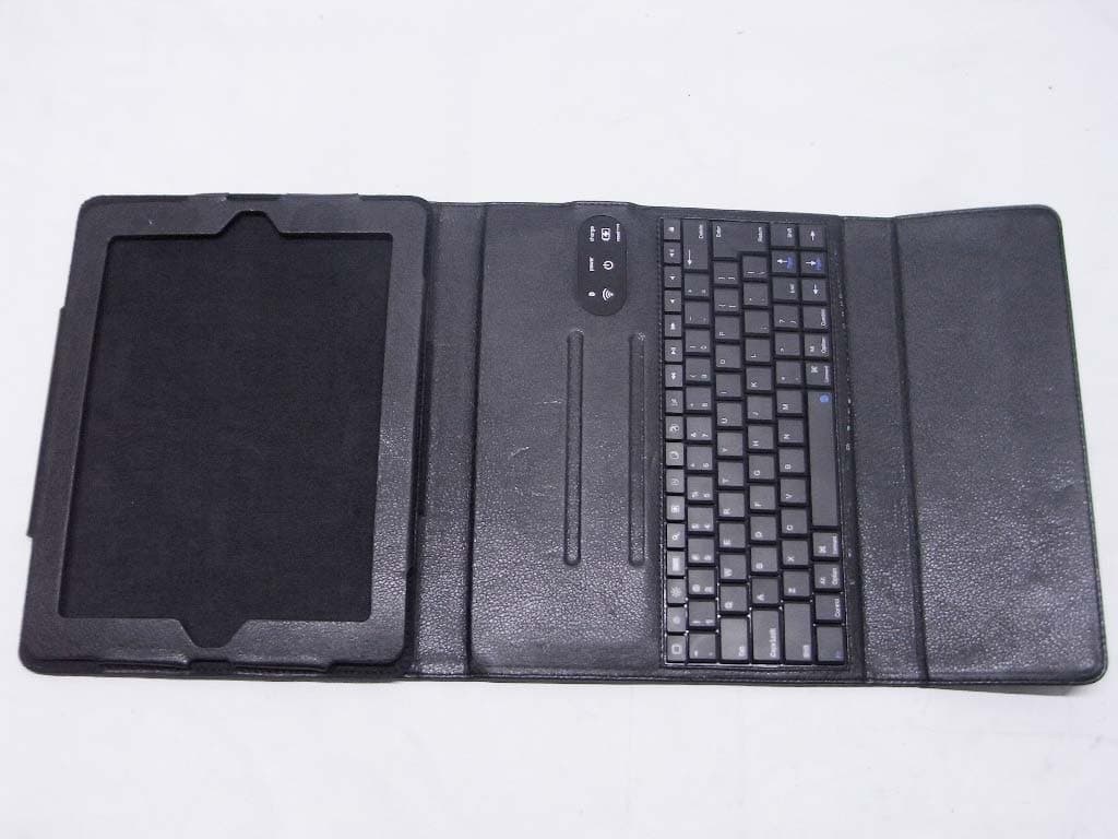
YS9-PD224
Apr 13, 2011RUBATA BLUETOOTH KEYBOARD CASE
Equipment Class
DXX - Part 15 Low Power Communication Device Transmitter
YS9-PD123
Sep 27, 2010TOCCATA BLUETOOTH KEYBOARD CASE
Equipment Class
DXX - Part 15 Low Power Communication Device Transmitter