YXA-WU106AM150M Wireless USB Adapter
HAOLIYUAN (SHENZHEN) ELECTRONIC CO., LTD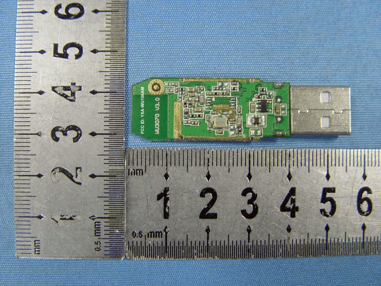
Click to zoom
Application Details
- Equipment Class
- DTS - Digital Transmission System
- Date of Grant
- Jul 21, 2011
- Application Purpose
- Original Equipment
- Date of Application
- Jul 21, 2011
- Equipment Note
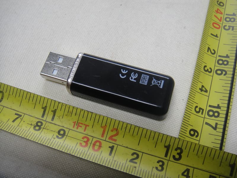
- 150M Wireless USB Adapter
- Frequency Range
- 2412.00000000 - 2462.00000000
- Country
- China
Documents & Files
Document Text
Text extracted from the exhibit documents filed with the FCC. Open a document above to read the original.
Users Manual
1 Wireless USB Adapter USER’S MANUAL 2 Chapter 1: Introduction 1.1 Features ...............................................................3 1.2 Contents of Package ................................................ 4 1.3 Product specification ................................................ 4 Chapter2: Installation 2.1 How to install the driver ............................................. 5 Chapter3: Configuration 3.1 Insert ..................................................................12 3.2 Configuration Interface .............................................13 3.2.1 Launch Config Utilities ..........................................13 3.2.2 Use Zero Configuration as Configuration Utilit ...............19 3.2.3 Switch to AP Mode ................................................19 3.2.4 Exit ..................................................................26 Chapter4: Glossary ................................................26 3 Chapter 1: Introduction The Wireless USB Adapter gives you the flexibility to install the PC or notebook PC in the most convenient location available, without the cost of running network cables. Its auto-sensing capability allows high packet transfer up to 150Mbps for maximum throughput, or dynamic range shifting to lower speeds due to distance or operating limitations in an environment with a lot of electromagnetic interference. It can also be compatible with all the 11/54Mbps wireless (802.11b/g) products. 1.1 Features ◆ pports 64/128-bit WEP, complies with 128 bit WPA standard (TKIP/AES) ◆ ports 135/121.5/108/81/54/40.5/27/13.5/65/58.5/52 /39/26/19.5/13/6.5/54/48/36/24/18/12/9/6/11/5.5/2/1Mbps wireless LAN data transfer rates ◆ Provides Soft AP, supports PSP connection ◆ Supports Ad-Hoc and Infrastructure modes ◆ Supports roaming between access points when configured in Infrastructure mode ◆ Eases to configure and provides monitoring information ◆ Supports Windows 2000/XP/VISTA/Win7/Linux/Macintosh ◆ Internal Antenna 4 1.2 Contents of Package Before you begin the installation, please check the items of your package. The package should include the following items: ◆ One USB Adapter ◆ One CD (Driver) If any of the above items is missing, contact your supplier as soon as possible. 1.3 Product specification Software Specification Standards IEEE 802.11n, IEEE 802.11g, IEEE 802.11b Wireless Signal Rates With Automatic Fallback 11n: Up to 150Mbps (Dynamic) 11g: Up to 54Mbps (Dynamic) 11b: Up to 11Mbps (Dynamic) Frequency Range 2.4-2.4835GHz Wireless Transmit Power 18dBm(MAX) Modulation Type DBPSK,DQPSK,CCK, OFDM Receiver Sensitivity 135M: -68dBm@10% PER 54M: -68dBm@10% PER 11M: -85dBm@8% PER Work Mode Ad-Hoc Infrastructure Wireless Security 64/128 bit WEP WPA/WPA2, WPA-PSK/WPA2-PSK (TKIP/AES) Support Operating System Windows 2000/XP/VISTA//Win7/Linux/Macintosh Hardware Specification Interface USB2.0 Hi-Speed connector Antenna Type Internal Omni-directional Antenna Operating Temperature 0°C~40°C (32°F~104°F) Storage Temperature -40°C~70°C (-40°F~158°F) Relative Humidity 10% ~ 90%, non condensation Storage Humidity 5%~95% non-condensing Weight 15.2g Dimensions 86mm × 26mm × 12mm 5 Chapter 2: Installation Before you proceed with the installation, please notice following descriptions. Note1: The following installation was operated under Windows VISTA. (Procedures are similar for Windows 2000/XP.) Note2: If you have installed the Wireless LAN USB Adaptor driver & utility before, please uninstall the old version first. 2.1 How to install the driver Please follow the instructions below to install the driver and utility of Wireless Adapter.. 2.1.1 Insert Wireless Adapter into the USB port on your PC. After that, the computer will automatically detect and open the Found New Hardware Wizard, please click “Cancel” and then use the driver and utility of Wireless Adapter. 6 2.1.2 Put the installation CD-ROM into the CD-ROM player and then go to WU3070’s directory to start the “Setup.exe” program. After that, the setup wizard will automatically start the “InstallShield Wizard” to continue setting up. First, you have to make sure that if you want to use the Wireless Adapter as the default adapter. 2.1.3 Please read the end user license agreement and click “I accept the terms of the license agreement”, then click Next. 7 2.1.4 please choose “Install driver and Ralink WLAN Utility” or “Install driver only”. 8 2.1.5 please choose “Ralink Configuration Tool” or “Microsoft Zero Configuration Tool”. 9 2.1.6 After click “Next” on the previous page, the installation wizard starts to install the software for WU3070. Then click “Install” to start installing the utility. 10 11 2.1.7 you can click “Finish” on the page to complete the installation. Chapter3: Configuration 3.1 Run configuration utility When you finish installing the driver and utility on the computer, you can start to use the utility of WU3070 to check the connection status of wireless connection. Right lick the icon of the utility “Ra” on the task bar, and choose “Launch Config Utilities” to start to use the utility; or you may double click on the icon to directly enter the utility. If you closed the utility of WU3070 and want to use it again, please click “Start → All Programs → Ralink Wireless → Ralink Wireless Utility” on the start 12 menu. After that, it will open the utility and the icon of the utility “Ra” will show on the task bar. 3.2 Configuration Interface To enter the utility program, please follow the instructions below. Right click the mouse on the utility icon on the taskbar, and you can click on the “Launch Config Utilities” to enter WU3070 utility; or you can just double click on the utility icon and enter the utility directly. 3.2.1 Launch Config Utilities (Click it to enter the utility program of WU3070) 3.2.1.1 Click the “Profile” button can “Add, Edit, Delete, Import, Export, Activate” new configuration. Clink “Profile List” can see wireless network mode. 13 3.2.1.1.1 Click “Add” button, Increase charact…
Text truncated - open the document above for the full version.
Cover Letter(s)
HAOLIYUAN (SHENZHEN) ELECTRONIC CO., LTD (July 12, 2011) To: SIEMIC, INC. 2206 Ringwood Avenue, San Jose, CA 95131 USA Dear Sir/Madam, Re: Project and Product Certification Representative Authorization Letter We, ______HAOLIYUAN (SHENZHEN) ELECTRONIC CO., LTD___hereby authorize SIEMIC, INC. to act as a Certification Body for certifying for the following project(s): Product Description:150M Wireless USB Adapter Model name: WU106A We affirm that between SIEMIC and __(client’s company name)___, any difference in understanding, including test plan, measurement methods, applicable standards and relevant procedures and processes have been resolved prior to commencement of testing activities. Sincerely, Client’s signature: Client’s name / title: Joliam Zhong / R&D Manager Contact information / address: No.07# LangSha Road, SongGang, BaoAn, ShenZhen, GangDong, China
Cover Letter(s)
HAOLIYUAN(SHENZHEN) ELECTRONIC CO.,LTD July 15, 2011 To: Federal Communications Commission Authorization and Evaluation Division Confidentiality Request regarding application for certification of FCC ID: YXA-WU106AM We hereby request confidential treatment of information accompanying this application as outlined below: - Block Diagram - Operational Description - Schematic - PCB Layout The above materials contain trade secrets and proprietary information not customarily released to the public. The public disclosure of these materials may be harmful to the applicant and provide unjustified benefits to its competitors. The applicant understands that pursuant to Section 0.457 of the Rules, disclosure of this application and all accompanying documentation will not be made before the date of the Grant for this application. Sincerely, Client’s signature: Client’s name / title: Joliam Zhong / R&D Manager Contact information / address: No.07# LangSha Road, SongGang, BaoAn, ShenZhen, GangDong, China
Cover Letter(s)
SCS-F26 Modular Approval Letter Page 1 of 4 Rev 4.0 2206 Ringwood Avenue San Jose, CA 95131 Tel: 408-526-1188 Fax: 408-526-1088 Email: [email protected] Modular Approval Declaration Letter Revision History Reason for Amendment (current / obsolete) From To Approved Date Initial Release (Obsolete) 1.0 1.0 Dec-04-2006 Added IC Modular Letter (Obsolete) 1.0 2.0 Feb 16 2009 Add LMA and MA option (Obsolete) 2.0 3.0 April 14 2010 Revised per RSS Gen issue 3.0 3.0 4.0 Jan 12 2011 SCS-F26 Modular Approval Letter Page 2 of 4 Rev 4.0 HAOLIYUAN(SHENZHEN) ELECTRONIC CO.,LTD (Date) July/15/2011 (Product name) FCC ID : YXA-WU106AM , is seeking FCC Authorization as a Single Modular transmitter / Single Limited Modular Approval (Please check one). The EUT meets the requirements for Single Modular approval / Single Limited Modular Approval (please check one) as detailed in FCC public Notice DA00-1407. Compliance to each of the requirements is described below : Questions are: 1. “The modular transmitter must have its own RF shielding.” Yes / No 2. “The modular transmitter must have buffered modulation/data inputs.” Yes / No 3. “The modular transmitter must have its own power supply regulation.” Yes / No 4. “The modular transmitter must comply with the antenna requirements of section 15.203 and 15.204(c).” Yes / No 5. “The modular transmitter must be tested in a stand-alone configuration.” Yes / No 6. “The modular transmitter must be labeled with its own FCC ID number.” Yes / No 7. “The modular transmitter must comply with any specific rule or operating requirements applicable to the transmitter and the manufacture must provide adequate instruction along with the module to explain any such requirements.” Yes / No 8. “The modular transmitter must comply with any applicable RF exposure requirements.” Yes / No Note: (1) LMA may be granted when one or more of the requirements in the table above cannot be demonstrated. LMA will also be issued in those instances where applicants can demonstrate that they will retain control over the final installation of the device, such that compliance of the end product is assured. In such cases, an operating condition on the LMA for the module must state that the module is only approved for use when installed in devices produced by a specific manufacturer. When LMA is sought, the application for equipment certification must specifically state how control of the end product into which the module will be installed, and will be maintained, such that full compliance of the end product is always ensured. (2) Host devices which contain separately certified modules do not need to be recertified, provided that they meet the following conditions: (i) The host device, as a stand-alone unit without any separately certified modules, complies with all applicable Radio Standards Specifications. (ii) The host device and all the separately certified modules it contains jointly meet the RF exposure compliance requirements of RSS-102, if applicable. (iii) The host device complies with the certification labeling requirements of each of the modules it contains. Note 1: Compliance of a module in its final configuration is the responsibility of the applicant. A host device will not be considered certified if the instructions regarding antenna configuration provided in the original description, of one or more separately certified modules it contains, were not followed. Example: A separately certified low-power transceiver module using Bluetooth technology which is housed in a desktop computer, laptop or peripheral does not require the overall system to be recertified, if the desktop computer, laptop or peripheral, as a stand-alone unit, complies with all applicable technical standards. SCS-F26 Modular Approval Letter Page 3 of 4 Rev 4.0 Client’s signature: Client’s name / title: Joliam Zhong / R&D Manager Contact information / address : N o.07# LangSha Road,SongGang,BaoAn,ShenZhen,GangDong,China SCS-F26 Modular Approval Letter Page 4 of 4 Rev 4.0 HAOLIYUAN(SHENZHEN) ELECTRONIC CO.,LTD LMA Declaration Letter We , (HAOLIYUAN (SHENZHEN) ELECTRONIC CO., LTD) declared that will retain control over the final installation of the device, (FCC/IC ID: YXA-WU106AM ) such that compliance of the end product is assured. In such cases, an operating condition on the LMA for the module must be only approved for use when installed in devices produced by a specific manufacturer. Client’s signature: Client’s name / title: Joliam Zhong / R&D Manager Contact information / addr ess: No.07# LangSha Road,SongGang,BaoAn,ShenZhen,GangDong,China
ID Label/Location Info
FCC Certification label Sample FCC ID: YXA-WU106AM
ID Label/Location Info
FCC Certification Label Location Sample Label location
Internal Photos
Antenna
RF Exposure Info
FCC ID : YXA-WU106AM Portable device According to §15.247(e)(i) and §1.1307(b)(1), systems operating under the provisions of this section shall be operated in a manner that ensures that the public is not exposed to radio frequency energy level in excess of the Commission’s guidelines. According to KDB 447498 (2)(a)(i) Frequency Range Low Frequency (MHz) High Frequency(MHz) Center frequency (MHz) 60/f SAR Limitation (mw) 2412 2462 2412 24.8 Maximum measured transmitter power Conducted Power (mw) Max Antenna Gain (dBi) EIRP (mw) 12.45 0 12.45 Threshold at which no SAR required is 24.8mw. Maximum Tx power is 12.45mw EIRP. Conclusion: No SAR is required. SIMULTANEOUS TRANSMISSION EVALUATION N/A
Test Report
Page 1 of 150 FCC ID: YXA-WU106AM ACCURATE TECHNOLOGY CO., LTD Report No.: ATE20111342 APPLICATION CERTIFICATION FCC Part 15C On Behalf of HAOLIYUAN (SHENZHEN) ELECTRONIC CO., LTD 150M wireless usb adapter Model No.: WU106A FCC ID: YXA-WU106AM Prepared for : HAOLIYUAN (SHENZHEN) ELECTRONIC CO., LTD Address : No. 07# LangSha Road, SongGang, BaoAn, ShenZhen GuangDong, China Prepared by : ACCURATE TECHNOLOGY CO., LTD Address : F1, Bldg. A, Changyuan New Material Port, Keyuan Rd. Science & Industry Park, Nanshan, Shenzhen, Guangdong P.R. China Tel: (0755) 26503290 Fax: (0755) 26503396 Report Number : ATE20111342 Date of Test : July 12-16, 2011 Date of Report : July 16, 2011 Page 2 of 150 FCC ID: YXA-WU106AM ACCURATE TECHNOLOGY CO., LTD Report No.: ATE20111342 TABLE OF CONTENTS Description Page Test Report Certification 1.GENERAL INFORMATION ..........................................................................................................5 1.1.Description of Device (EUT)....................................................................................................................5 1.2.Description of Test Facility ......................................................................................................................6 1.3.Measurement Uncertainty.........................................................................................................................6 2.MEASURING DEVICE AND TEST EQUIPMENT ..................................................................... 7 3.OPERATION OF EUT DURING TESTING ................................................................................. 8 3.1.Operating Mode ........................................................................................................................................8 3.2.Configuration and peripherals ..................................................................................................................8 4.TEST PROCEDURES AND RESULTS ......................................................................................... 9 5.6DB BANDWIDTH MEASUREMENT ........................................................................................ 10 5.1.Block Diagram of Test Setup..................................................................................................................10 5.2.The Requirement For Section 15.247(a)(1) ............................................................................................10 5.3.EUT Configuration on Measurement .....................................................................................................10 5.4.Operating Condition of EUT ..................................................................................................................10 5.5.Test Procedure ........................................................................................................................................11 5.6.Test Result ..............................................................................................................................................11 6.MAXIMUM PEAK OUTPUT POWER ....................................................................................... 22 6.1.Block Diagram of Test Setup..................................................................................................................22 6.2.The Requirement For Section 15.247(b)(3)............................................................................................22 6.3.EUT Configuration on Measurement .....................................................................................................22 6.4.Operating Condition of EUT ..................................................................................................................22 6.5.Test Procedure ........................................................................................................................................23 6.6.Test Result ..............................................................................................................................................23 7.POWER SPECTRAL DENSITY MEASUREMENT.................................................................. 34 7.1.Block Diagram of Test Setup..................................................................................................................34 7.2.The Requirement For Section 15.247(e).................................................................................................34 7.3.EUT Configuration on Measurement .....................................................................................................34 7.4.Operating Condition of EUT ..................................................................................................................34 7.5.Test Procedure ........................................................................................................................................35 7.6.Test Result ..............................................................................................................................................35 8.BAND EDGE COMPLIANCE TEST ........................................................................................... 46 8.1.Block Diagram of Test Setup..................................................................................................................46 8.2.The Requirement For Section 15.247(d) ................................................................................................46 8.3.EUT Configuration on Measurement .....................................................................................................46 8.4.Operating Condition of EUT ..................................................................................................................47 8.5.Test Procedure ........................................................................................................................................47 8.6.Test Result ..........................…
Text truncated - open the document above for the full version.
Test Setup Photos
Conducted emissions test EUT Radiated emissions test < 1GHz Radiated emissions test > 1GHz EUT
Contact Information
Applicant
Joliam Zhong(R&D Manager)
Test Firm
Accurate Technology Co., Ltd.Sean Liu
Technical Specifications
| # | Rule Parts | Frequency Range | Power Output |
|---|---|---|---|
| 1 | 15C | 2.41 GHz - 2.46 GHz | 12.45 mW |
Other Applications from HAOLIYUAN (SHENZHEN) ELECTRONIC CO., LTD
YXA-WUXXXEC
Mar 20, 2011802.11n Wireless USB Adapter
Equipment Class
DTS - Digital Transmission System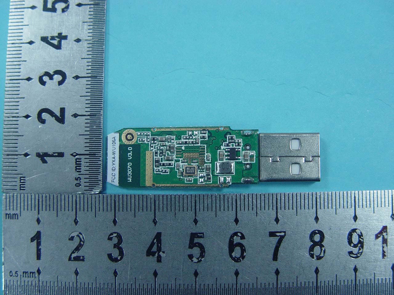
YXA-WU106A
Nov 11, 2010150M Wireless USB Adapter
Equipment Class
DTS - Digital Transmission System