FCCID.CO- FCC ID Database
HomeCompaniesEquipment ClassesSearch

© 2026 FCC ID Database. All rights reserved.

AboutContactData sourced from FCC public records
  1. Home/
  2. Cydle Corp./
  3. YXQM7

YXQM7MULTI PAD

Cydle Corp.
MULTI PAD - FCC ID YXQM7 - Cydle Corp.
Click to zoom

Application Details

Equipment Class
DTS - Digital Transmission System
Date of Grant
Jan 31, 2011
Application Purpose
Original Equipment
Date of Application
Jan 30, 2011
Equipment Note
MULTI PAD
Frequency Range
2412.00000000 - 2462.00000000
Company
Cydle Corp.
Country
South Korea

Documents & Files

Select a file to view

Users Manual

↗

Cover Letter(s)

↗
↗

External Photos

↗

ID Label/Location Info

↗

Internal Photos

↗

Operational Description

↗

Test Report

↗

Test Setup Photos

↗

Document Text

Text extracted from the exhibit documents filed with the FCC. Open a document above to read the original.

Users Manual

IntroductionPre-cautionSafety and Handling InformationImportant Safety Information Before you startM7 at a GlanceBatteryDetachable StandGetting StartedTurning the M7 MultiPAD On/OffHome Screen and Applications TabHow to Manage Icons Status Indicator on DeviceMusic PlaybackGalleryVideo GalleryPhoto Gallery HDMIHow to Use HDMIWeb Browsing Connecting to the InternetTo Start Internet BrowserBookmarkSyncingHow to Use the Mini USB PortHow to Use Yo ur Micro SD Pairing a Wireless DeviceApp SquareTo Start App SquareManage AccountApplicationSpecificationNoticeCopyrightWarranty Card 2345678891012-131314 151617181920212223242526272829 Contents Introduction We hope you will find the instru ctions in this manual clear and easy to fo llow. Please take a few minutes to look through the Quick Manual to learn how to use all the features of Cydle M7 MultiPAD. Web site Thank you for choosing Cydle Please visit our website or contact a Cy dle representative if you have any inqu ires while using the Cydle M7 MultiPAD. Get the latest software update at the Cydle website at no cost.Register as a Cydle Member for the latest upda tes, promotions and ne w product information. Contact http://www.cydle.com e-mail [email protected] Cydle customer service Toll free number 1-877-810-5818 What’s in the Box Box includes Cydle M7 MultiPAD Manual Earphone Mini USB Cable Wall Charger 2 Pr Be sure to carefully read the operating instructions and adhere to the safety precautions before using your M7 MultiPAD to ensur e correct usage and user safety. Cydle Corpora tion will not be responsible for incidents that occur due to failing to follow inst ructions presented. This information applies to all Cydle Corporation products. Safety and Handling Information This product should be used for personal use only and used as intended in accordance with the user’s manual. Do not operate or adjust settings while driving , cycling, or walking near traffic.Stop using the M7 MultiPAD if you find it disruptive or dist racting while operating any type of vehicle, or performing any other activity that requires your fu ll attention. Check and obey the applicab le laws and regulations on the use of earphones and devices such as M7 MultiPAD in the areas where you drive or ride. Be careful and attentive while driving. Pre-caution Do not drop, disassemble, open, crush, be nd, deform, puncture, shred, microwave, incinerate, paint, or insert foreign objects into M7 MultiPAD.Unit contains electronic components that can be perm anently damaged when expose d to shock or vibration. Please keep your unit in a stable place and avoid dropping the unit. Do not operate unit in high–shock and high-vibration environments.Do not attempt to take apart, open, service, or modify the product. Refer all servicing to qualified personnel. Clean only with cloth dampened with wa ter, gently wipe dry with dry cloth. Do not apply liquid di rectly to the unit. Never attempt to repair or modify the M7 MultiPAD your self. If the M7 MultiPAD has been submerged in water, punctured, or subjected to a severe fall, do not use it until you take it to an Cydle Authorized Service Provider. The M7 MultiPAD doesn’t contain any user-serviceable parts. Disassem bling the M7 MultiPAD, includ ing the removal of the back cover, may cause damage that is not covered under warranty. For service information, please visi t our support center at www.cydle.com The rechargeable battery in M7 MultiPAD should be re placed only by an Cydle Authorized Service Provider. Operating in a safe place:Proper handling:Repair Customer Service contact 3 Pr Caution: Power Adapter Usage Important safety Information When using the Power Adapter to charge the M7 MultiPAD, make sure that the Power Adapter is plugged into the power outlet. Do n ot connect or disconnect the Power Adapter while hands are wet. Do not us e any other Power Adapter other than the AC/DC Power Adapter cert ificated by Cydle to charge your M7 MultiPAD. (Make sure th at the rated Voltage of the M7 MultiPAD is 5V) The Power Adapter may become warm during normal use. Always al low adequate ventilation around the Power Adapter and use care wh en handling. Pre-caution 1. The power cord or plug has become frayed or damaged.2. The adapter is exposed to rain, liquids, or excessive moisture.3. The adapter case has become damaged.4. You suspect the adapter needs service or repair.5. You want to clean the adapter. Unplug the Power Adapter if any of the following conditions exist: Caution: Battery Care & Recycle regulation THERE IS A RISK OF EXPLOSION IF BATTERY IS REPLACED BY AN INCORRECET TYPE. This unit contains materials such as batte ry, circuit boards, cables, electromagnetic compatibility gaskets and connectors which may contain lead and copper/beryllium alloys that require special handling and disposal at en d of life. Before this unit is disposed of, these materials must be removed and recycled or discarded according to applicable regulations. 4 M7 MultiPAD at a Glance MicrophonePower ButtonVolume KeysHome ButtonMenu Button Before you start e f ⓕⓖⓗⓘⓙ ⓐⓑⓒⓓⓔ Back ButtonMicrophone Jack3.5mm Earphone JackMini USB PortHDMI Port ⓚⓛⓜⓝ Power JackExternal SpeakerHook for Detachable StandMicro SD SlotStand bodySupport & cover Before you start Pq 5 Battery 6 Before you start f Before you start Charge the M7 MultiPAD with the original Power Adapter included in the box. Use only the adapter(5V,2A) included in the box. 1. The Power Jack is located on the bottom right of the unit.2. Plug in the Power Adapter to the Power Outlet.3. Connect the Power Adapter to the M7 MultiPAD.4. The M7 MultiPAD will begin charging. The Battery Icon will change to the Charging Icon on the top right of the screen. Charging the Battery Understanding Battery Status When the M7 MultiPAD is conn ected to a power source, the battery icon changes to show th at the battery is charging or fully charged. When the M7 MultiPAD isn’t co nnected to a power source, a battery icon on the M7 Mult…

Text truncated - open the document above for the full version.

Cover Letter(s)

Rev 11/20/07 12th Floor, Kofomo Tower, 16-3, Sunae-dong, Bundang-Gu, Sungnam-City, Kyonggi-Do, Korea Tel. : +82) 31 726 9970, Fax. : +82) 31 713 9773 http://www.cydle.com Federal Communications Commission Authorization and Evaluation Division Confidentiality Request regarding application for certification of FCC ID: YXQM7 Pursuant to Sections 0.457 and 0.459 of the Commission’s Rules, we hereby request confidential treatment of information accompanying this application as outlined below: Exhibit Type File Name Schematics CONF APPENDIX M7 Schem.pdf Parts list CONF APPENDIX M7 PartsLst.pdf Block diagram CONF APPENDIX M7 BlkDia.pdf Operational Description(Theory of Operation)CONF APPENDIX M7 OpDes.pdf The above materials contain trade secrets and proprietary information not customarily released to the public. The public disclosure of these materials may be harmful to the applicant and provide unjustified benefits to its competitors. The applicant understands that pursuant to Section 0.457 of the Rules, disclosure of this application and all accompanying documentation will not be made before the date of the Grant for this application. Pursuant to DA04-1705 June 15, 2004 of the Commission’s public notice, we also request temporary confidential treatment of information accompanying this application as outlined below: Exhibit Type File Name External Photos CONF APPENDIX M7 ExtPho.pdf Internal Photos CONF APPENDIX M7 IntPho.pdf Sincerely, ------------------------------------- Jinny Rho / Assistance Manager E-mail : [email protected]

Cover Letter(s)

12th Floor, Kofomo Tower, 16-3, Sunae-dong, Bundang-Gu, Sungnam-City, Kyonggi-Do, Korea Tel. : +82) 31 726 9970, Fax. : +82) 31 713 9773 http://www.cydle.com POWER OF ATTORNEY DATE : DEC 2. 2010. Federal Communications Commission Authorization and Evaluation Division 7435 Oskland Mills Road, Columbia, MD 21046 To Whom It May Concern : We the undersigned, hereby authorize Korea EMC Laboratory Co., Ltd. on our behalf, to apply to the FEDERAL COMMUNICATIONS COMMISSION on our equipment. Any and all acts carried out by Korea EMC Laboratory Co., Ltd. on our behalf shall have the same effect as acts of our own. This authorization expires on DEC 2. 2011. This is to advise that we are in full compliance with the Anti-Drug Abuse Act. We, the applicant, are not subject to a denial of federal benefits pursuant to Section 5301 of the Anti-Drug Act of 1988, 21 USC853a, and no party to the application is subject to a denial of federal benefits pursuant to that section. Cydle Corp. . Jinny Rho / Assistance Manager E-mail : [email protected]

External Photos

External Photographs

Internal Photos

Internal Photographs of EUT Main Board WLAN Bluetooth Switch Board LCD Battery

Operational Description

Dielectric Chip Antenna - Application Frequency Band[MHz] Bluetooth2400 ~ 2485 WiFi / Zigbee2400 ~ 2485 S-DMB2630 ~ 2655 Wibro 2300 ~ 2390 band1 : 2300 ~ 2327 band2 : 2331.5 ~ 2358.5 bnad3 : 2363 ~ 2390 Original Design Chip Antenna Data Sheet - P/N : SDBTPTR3015 - Dielectric Chip Antenna ■ SDBTPTR3015 Dimension ParameterLWTABCDE Value[mm] 3.0 ±0.1 1.5 ±0.1 1.2 ±0.1 1.00.550.41.10.65 Unless Specified tolerances are ± 0.05 mm Dielectric Chip Antenna ■ AutoCAD Drawing of Reference PCB Design for SDBTPTR3015 Product 41 2 3 Dielectric Chip Antenna ■ PCB Drawing Top View Case #1 <Default> 12 3 4 Case #2 12 3 4 Case #3 12 3 4 Case #4 12 3 4 Bottom View <Equivalent Circuit> Dielectric Chip Antenna ■ Matching Value Band (MHz) Matching Value (Default) Bluetooth / WiFi / Zigbee (2400 ~ 2485) Connector N/C Ant. 100pF 1.8pF 100 pF N/C S-DMB ( 2630 ~ 2655) Connector N/C Ant. 100pF 1.0nH 100 pF N/C Wibro (2300 ~ 2390) band1:2300~2327 band2:2331.5~2358.5 bnad3:2363~2390 Connector N/C Ant. 100pF 2.0pF 100 pF N/C Dielectric Chip Antenna - 3D Passive Gain For Bluetooth / WiFi / Zigbee ■ Test Result for Ver 0.0 SWR & Smith chart3D Peak [dBi] Average [dBi] Efficiency [%] 2400MHz1.96-0.9780.18 2425MHz1.99-0.6685.92 2445MHz1.74-0.8582.42 2465MHz1.27-1.2575.12 2485MHz0.86-1.6468.59 ■ Radiation PatternVer 0.0 3D Passive Dielectric Chip Antenna - 3D Passive Gain For S-DMB ■ Test Result for Ver 0.0 SWR & Smith chart3D Peak [dBi] Average [dBi] Efficiency [%] 2627MHz4.33-0.3891.80 2642MHz4.67-0.3692.06 2657MHz4.71-0.5688.02 ■ Radiation PatternVer 0.0 3D Passive Dielectric Chip Antenna - 3D Passive Gain For Wibro ■ Test Result for Ver 0.0 SWR & Smith chart3D Peak [dBi] Average [dBi] Efficiency [%] 2300MHz2.51-0.8482.52 2322.5MHz 2.68-0.7883.71 2345MHz3.15-0.4590.20 2367.5MHz 3.02-0.7883.76 2390MHz3.09-0.8682.12 ■ Radiation PatternVer 0.0 3D Passive

Test Report

KEL-D-QP-25-24/2 Page of Pages: 2/36 FCC ID : YXQM7 Report Ref. No : KEL10-F10074 Korea EMC Laboratory Co., Ltd. KEL Korea EMC Laboratory 0. REPORT REVISION HISTORY Date Revision Page no. January 11, 2011 Issued All This report shall not be reproduced except in full, without the written approval of Korea EMC Laboratory Co., Ltd. This document may be altered or revised by Korea EMC Laboratory Co., Ltd. personnel only, and shall be noted in the revision section of the document. Any alteration of this document not carried out by Korea EMC Laboratory Co., Ltd. will constitute fraud and shall nullify the document. KEL-D-QP-25-24/2 Page of Pages: 3/36 FCC ID : YXQM7 Report Ref. No : KEL10-F10074 Korea EMC Laboratory Co., Ltd. KEL Korea EMC Laboratory TABLE OF CONTENTS 0. REPORT REVISION HISTORY 2 1. TEST LABORATORY 5 1.1 General 5 1.2 Certificate of designated testing laboratory 5 2. DESCRIPTION OF THE EQUIPMENT UNDER TEST 6 2.1 Characteristic 6 2.2 Applied standard 6 2.3 Submitted documents 6 2.4 Channel chart 7 3. TEST COMDITIONS 8 3.1 Description of test configuration 8 3.2 List of peripherals 8 3.3 Uncertainty 8 3.4 Environment condition 8 4. SUMMARY OF TEST RESULTS 9 5. TEST AND RESULTS 10 5.1 AC Power conducted emission 10 5.1.1 Test procedures 10 5.1.2 Limits of AC power conducted emission 10 5.1.3 Test instruments 10 5.1.4 Test results 11-13 5.2 Out of band emission & Band edge 14 5.2.1 Test procedures 14 5.2.2 Limits of out of band emission 14 5.2.3 Test instruments 15 5.2.4 Test results 15-24 5.3 Minimum 6 dB bandwidth 25 5.3.1 Test procedures 25 5.3.2 Limit of minimum 6 dB bandwidth 25 5.3.3 Test instruments 25 5.3.4 Test results 25-29 5.4 Maximum peak out power 30 5.4.1 Test procedures 30 5.4.2 Limit of maximum peak out power 30 5.4.3 Test instruments 30 5.4.4 Test results 30 KEL-D-QP-25-24/2 Page of Pages: 4/36 FCC ID : YXQM7 Report Ref. No : KEL10-F10074 Korea EMC Laboratory Co., Ltd. KEL Korea EMC Laboratory 5.5 Peak power spectral density 31 5.5.1 Test procedures 31 5.5.2 Limit of peak power spectral density 31 5.5.3 Test instruments 31 5.5.4 Test results 31-35 5.6 Antenna requirement 36 5.6.1 Regulation 36 5.6.2 Antenna connected construction 36 5.7 RF exposure 36 KEL-D-QP-25-24/2 Page of Pages: 5/36 FCC ID : YXQM7 Report Ref. No : KEL10-F10074 Korea EMC Laboratory Co., Ltd. KEL Korea EMC Laboratory 1. TEST LABORATORY 1.1 General Name of Test Laboratory Korea EMC Laboratory Co., Ltd. President Won-Hyang Oh Address 390 Bora-dong, Giheung-gu, Yongin-si, Gyeonggi-do, Republic of Korea (446-904) TEL +82-31-286-5881 FAX +82-31-286-2661 e-mail [email protected] 1.2 Certificate of designated testing laboratory Area and Category Regulation Registration & Certification No. Mark. Radio Research Agency EMI(Radiated & Conducted emission) EMS(Radiated Immunity) Safety Radio Communication Part Regulation of KCC No. 2009-48 (2009. 11. 10) KR0002 Korea Laboratory Accreditation Scheme (KOLAS) EMI(Radiated & Conducted emission) EMS(Radiated Immunity) Safety Road Vehicle component test(EMC) Military EMC(MIL-STD-461E) KS A ISO/IEC 17025:2006 No. 154 FCC Part 15 & 18 EMI(Radiated & Conducted emission) ANSI 63.4 90751 (KR0002) VCCI EMI(Radiated & Conducted emission) VCCI C-2314 R-2139 R-2140 UL Korea Ltd. Safety Star Alliance Program - European Conformity EMC & Safety 2004/108/EC 2006/95/EC - TUV SUD Certification after Recognition of Agent’s Testing EMC ISO/IEC 17025 ROK1006C KEL-D-QP-25-24/2 Page of Pages: 6/36 FCC ID : YXQM7 Report Ref. No : KEL10-F10074 Korea EMC Laboratory Co., Ltd. KEL Korea EMC Laboratory 2. DESCRIPTION OF THE EQUIPMENT UNDER TEST The product specification described herein was obtained from the product data sheet or user’s manual 2.1 Characteristics Product name Multi PAD Model no. M7 FCC ID YXQM7 Operation frequency 802.11 b/g : 2412 MHz – 2462 MHz RF power 802.11 b/g : 10.94 dBm(12.41 mW) Spread spectrum method 802.11 b/g : DSSS, OFDM Modulation type 802.11 b : CCK, DQPSK, DBPSK 802.11 g : 64QAM, 16QAM, QPSK, BPSK Data rate 802.11 b : 11.0 / 5.5 / 2.0 / 1.0 Mbps 802.11 g : 54.0 / 48.0 / 36.0 / 24.0 / 18.0 / 12.0 / 9.0 / 6.0 Mbps Number of channel 802.11 b/g : 11 Channel Antenna type / max. gain 802.11 b/g : Chip Antenna / 1.99 dBi Power source DC 5.0 V(Adapter) DC 3.7 V(Battery) Size 181 mm X 122 mm X 20.4 mm Interface ports USB 2.0, HDMI, Micro SD, MIC, Audio out Accessory USB Cable, Adapter, Earphone 2.2 Applied standard - FCC part 15, subpart C(15.247_DTS) - ANSI C63.4_2003 Note : It has been verified to comply with requirements of FCC part 15, subpart B, Class B(DoC). The test report has been issued separately 2.3 Submitted documents - Block diagram - Schematic diagram - Antenna specification - Part list(B.O.M) - User manual KEL-D-QP-25-24/2 Page of Pages: 7/36 FCC ID : YXQM7 Report Ref. No : KEL10-F10074 Korea EMC Laboratory Co., Ltd. KEL Korea EMC Laboratory 2.4 Channel chart 802.11 b/g(11 Channel) Channel Freq. (MHz) Channel Freq. (MHz) Channel Freq. (MHz) Channel Freq. (MHz) 1 2412 2 2417 3 2422 4 2427 5 2432 6 2437 7 2442 8 2447 9 2452 10 2457 11 2462 ▪ Measurement Channel 802.11 b/g : Low(2412 MHz), Middle(2437 MHz), High(2462 MHz) ▪ Test rate : 802.11 b/g(11, 54 Mbps) KEL-D-QP-25-24/2 Page of Pages: 8/36 FCC ID : YXQM7 Report Ref. No : KEL10-F10074 Korea EMC Laboratory Co., Ltd. KEL Korea EMC Laboratory 3. TEST CONDITIONS 3.1 Description of test configuration The EUT has been tested as an independent unit with other necessary accessories or support unit. The following support units or accessories were used to form a representative test configuration during the tests. 3.2 List of peripherals Type Model no. Serial no. Manufacturer EUT(Multi PAD) M7 - Cydle Corp. Adapter PA-050200SN - Perfect Power Lab top PP11L CN-0D4571- 46843-5AB-0772 Dell Asia Pacific Sdn. Adapter PA-1900-02DK CN-CO1104- 71815-51L-00F9 Dongguang Litepower 2 nd Plant LCD Monitor U2410f CN-0G550M- 72312-99N-016L Innocom Technology(Shenzhen) Co., Ltd. MIC - - - Earphone - - Cydle Corp. 3.3 Un…

Text truncated - open the document above for the full version.

Test Setup Photos

Test Setup Photographs

Contact Information

Applicant

Jinny Rho(Assistance Manager)
[email protected]82-31-726-9970Fax: 82-31-726-0162

Test Firm

Korea EMC Laboratory Co., Ltd.Man-Sung Cho
[email protected]82-31-286-5881Fax: 82-31-8059-1154

Technical Specifications

#Rule PartsFrequency RangePower Output
115C2.41 GHz - 2.46 GHz12.41 mW
Confidentiality
Long Term
Grant Notes
Power listed is conducted. The antenna(s) used for this transmitter must not transmit simultaneously with any other antenna or transmitter, except in accordance with FCC multi-transmitter product procedures.

Other Applications from Cydle Corp.

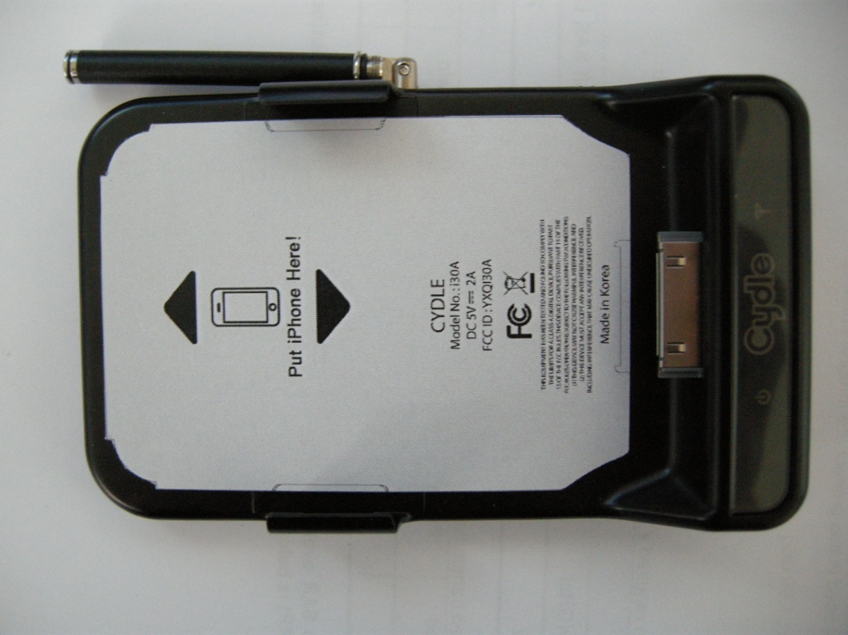
MOBILE TV RECEIVER - FCC ID YXQI30A - Cydle Corp.
YXQI30A

MOBILE TV RECEIVER

May 22, 2011

Equipment Class

DTS - Digital Transmission System