YY5YZ9600Headphone Module
Shenzhen Toopo Electronics Co.,Ltd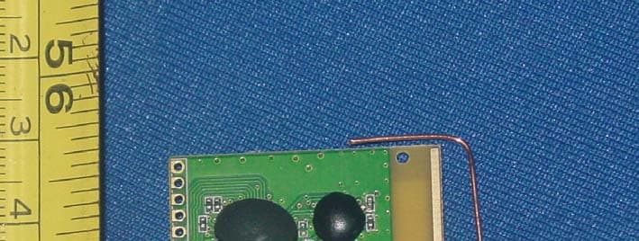
Click to zoom
Application Details
- Equipment Class
- DXX - Part 15 Low Power Communication Device Transmitter
- Date of Grant
- Nov 23, 2010
- Application Purpose
- Original Equipment
- Date of Application
- Nov 23, 2010
- Equipment Note
- Headphone Module
- Frequency Range
- 2403.00000000 - 2479.00000000
- Country
- China
Documents & Files
Document Text
Text extracted from the exhibit documents filed with the FCC. Open a document above to read the original.
Users Manual
2.4GMultifunctionWirelessHeadphone Module Specification 2.4G MultifunctionWireless Headphone ModuleSpecification YZ9600 and YZ9602 V1.12010/10/08 This specification is subject to change without prior notice 1 V1.1 2.4GMultifunctionWirelessHeadphone Module Specification SpecificationRevisionHistory Version Content Date V1.0 Original Ve r s i o n 2010/08/08 This specification is subject to change without prior notice 2 V1.1 2.4GMultifunctionWirelessHeadphone Module Specification This specification is subject to change without prior notice 3 V1.1 2.4GMultifunctionWirelessHeadphone Module Specification RECEIVER MODULE_YZ9600 PINDEFINITIONANDRATING Pin No Pin Name DescriptionRating 13 GND Ground 12 +3.3V Power supply +3.3V 11 Vdet Low voltage alarm sense input +2.2V~+3.5V 10 Mute Audio mute on/off input -0.3V~+3.5V 9 Sleep Module sleep control input -0.3V~+3.5V 8 Vo l - Vo l u m e down -0.3V~+3.5V 7 Vo l + Vo l u m e up -0.3V~+3.5V 6 Play/Pause Play/Pause key input -0.3V~+3.5V 5 LED LED driver output <10mA 4 MIC IN Connect to positive terminal of MIC The negative terminal of MIC should be connected to AGND 3 AGND Microphone and Speaker GND 2 SPKL Left channel speaker output Vp-p=1.4V 1 SPKR Right channel speaker output Vp-p=1.4V This specification is subject to change without prior notice 4 V1.1 2.4GMultifunctionWirelessHeadphone Module Specification 1. RECEIVER MODULE_YZ9600SPECIFICATION ParameterMinTypMaxUnit Supply Voltage(+3.3V) 3.3V Vo l t Operation Current (VBUS = VBAT = 3.8V) 384045mA Sleep Current 200uA Mic Sampling Rate 16 KHz A/D Resolution 10 bits SNR of Mic Circuit 50 55 dB 3dB Vo i c e BW 60 6500 Hz Mic channels 1 Audio THD+N(0dB@1KHz) 0.1% 0.5% Audio output SNR 55 62 dB Audio Resolution 16 bit Audio Sample Rate 48 KHz Audio Latency 64 mS Audio data compression yes Audio Channels 2 L/R Channels Separation 55 62 dB Audio output Band(with 32ohm Loading) 20 22000 Hz Audio output Range 1400 mV(p-p) Operating Frequency 2403 2479 MHz RF-channels 77 RX Sensitivity -85 dBm Channel spacing 1 MHz Air Data Rate 2 Mbps Modulation GFSK Radiated Power -15 dBm Operation Range 10 Meters/light of sight This specification is subject to change without prior notice 5 V1.1 2.4GMultifunctionWirelessHeadphone Module Specification 2. TRANSMITTERMODULE_YZ9602PINDEFINITIONAND RATING Pin No Pin Name DescriptionRating 1 Vbus Power supply +4.5V~+5.5V 2 D+ USB D+ terminal 3 D- USB D- terminal 4 GND Ground 3. TRANSMITTERMODULE_YZ9602SPECIFICATION Parameter MinTypMaxUnit Supply Voltage 4.5 5.0 5.5 Vo l t Operation Current 38 mA Audio Resolution 16 bit Audio Sample Rate 48 KHz Audio data compression yes Audio Channels 2 USB2.0(Full Speed) Audio Input Type Isochronousmode Operating Frequency 24032479MHz RF-channles 77 Channel spacing 1 MHz Air Data Rate 2 Mbps Modulation GFSK Radiated Power -10 dBm Operation Range 10 Meters/light of sight Antenna Type PCB printed antenna This specification is subject to change without prior notice 6 V1.1 2.4GMultifunctionWirelessHeadphone Module Specification 4. FUNCTIONS DESCRIPTION ● YZ9600 is the receiver module (headset side),the transmitter side could be YZ9602. With YZ9602, only digital signal from USB is the audio source. ● The MIC function of YZ9600 is operable only when the transmitter side is connected to USB port. The MIC function is automatically activated when a 2-way conversion is to go, and deactivated when the conversion is over. During conversion, the audio playing switches to mono mode. ● When MIC function is not activated, one transmitter (YZ9602) can send audio signals to 2 receiver modules(YZ9600) simultaneously without causing interference. This feature suits t application for which multi-users share a signal audio source. ● 5. FUNCTIONS KEY CONNECTIONDESCRIPTION keystoke Apellation Functions Description Power on/off Switch the module between normal operation mode and standby mode (Vol+)+(Vol-) Used for ID pairing. Pressing the key again will abort the ID pairing operation Vo l + Keys for volume adjustment Vo l - Keys for volume adjustment Mute Key for muting the audio output Play“+” Vo l + Prev Play“+” Vo l - Next ON/OFF“+” Vo l - Stop Play Mute“+”Sleep MIC Mute This specification is subject to change without prior notice 7 V1.1 2.4GMultifunctionWirelessHeadphone Module Specification 6. FREQUENCY RESPONSE GRAPH 均方根(dB) 2.00 频率响应 1.00 0.00 -1.00 -2.00 1.00 2.00 3.00 率(Hz/ 4.00 5.00 10Hz 100Hz 1KHz10KHz 100KHz This specification is subject to change without prior notice 8 V1.1 Federal Communication Commission Interference Statement This equipment has been tested and found to comply with the limits for a Class B digital device, pursuant to Part 15 of the FCC Rules. These limits are designed to provide reasonable protection against harmful interference in a residential installation. This equipment generates uses and can radiate radio frequency energy and, if not installed and used in accordance with the instructions, may cause harmful interference to radio communications. However, there is no guarantee that interference will not occur in a particular installation. If this equipment does cause harmful interference to radio or television reception, which can be determined by turning the equipment off and on, the user is encouraged to try to correct the interference by one of the following measures: - Reorient or relocate the receiving antenna. - Increase the separation between the equipment and receiver. - Connect the equipment into an outlet on a circuit different from that to which the receiver is connected. - Consult the dealer or an experienced radio/TV technician for help. This device complies with Part 15 of the FCC Rules. Operation is subject to the following two conditions: (1) This device may not cause harmful interference, and (2) this device must accept any interference received, including interference that may cause undesired operation. FCC Caution: Any changes or modifications not expressly approved by the party responsible for compliance could void …
Text truncated - open the document above for the full version.
External Photos
Label Location Antenna Location
ID Label/Location Info
FCC ID label Label size:20mm*5mm Label location FCC ID:YY5YZ9600
Test Report
FCC ID: YY5YZ9600 NS Technology Co., Ltd. Report No. NSE-F 10115464 Page 1 of 60 FCC TEST REPORT for Shenzhen Toopo Electronic Co.,Ltd Wireless Module Model Number: YZ9600 Prepared for : Shenzhen Toopo Electronic Co.,Ltd Address : Baigong’ao Industrial Zone,Xikeng New Village,GuanLan Town, Bao'an District,Shenzhen City,Guangdong Province,China Prepared By : NS Technology Co., Ltd. Address : Chenwu Industrial Zone, Houjie Town, Dongguan City, Guangdong, China Tel: +86-769-85935656 Fax: +86-769-85991080 Report Number : NSE-F10115464 Date of Test : Nov. 9~ Nov. 12, 2010 Date of Report : Nov. 15, 2010 FCC ID: YY5YZ9600 NS Technology Co., Ltd. Report No. NSE-F 10115464 Page 2 of 60 TABLE OF CONTENTS Test Report Declaration Page 1. GENERAL PRODUCT INFORMATION .......................................................................... 4 1.1. Product Function ..........................................................................................................................4 1.2. Description of Device (EUT) .......................................................................................................4 1.3. Independent Operation Modes .....................................................................................................4 1.4. Test Supporting System ...............................................................................................................4 2. TEST SITES........................................................................................................................... 5 2.1. Test Facilities ...............................................................................................................................5 2.2. List of Test and Measurement Instruments ..................................................................................6 3. TEST SET-UP AND OPERATION MODES ..................................................................... 7 3.1. Principle of Configuration Selection............................................................................................7 3.2. Block Diagram of Test Set-up......................................................................................................7 3.3. Test Operation Mode and Test Software......................................................................................7 3.4. Special Accessories and Auxiliary Equipment ............................................................................7 3.5. Countermeasures to Achieve EMC Compliance..........................................................................7 4. TEST SUMMARY................................................................................................................. 8 5. EMISSION TEST RESULTS............................................................................................... 9 5.1. Conducted Emission at The Mains Terminals Test......................................................................9 5.2. Radiated Emission......................................................................................................................12 5.3. 20dB Bandwidth ........................................................................................................................42 5.4. Band Edge ..................................................................................................................................44 FCC ID: YY5YZ9600 NS Technology Co., Ltd. Report No. NSE-F 10115464 Page 3 of 60 NS Technology Co., Ltd. Applicant: Address: Shenzhen Toopo Electronic Co.,Ltd Baigong’ao Industrial Zone,Xikeng New Village,GuanLan Town, Bao'an District,Shenzhen City,Guangdong Province,China Manufacturer: Address: Shenzhen Toopo Electronic Co.,Ltd Baigong’ao Industrial Zone,Xikeng New Village,GuanLan Town, Bao'an District,Shenzhen City,Guangdong Province,China E.U.T: Wireless Module Model Number: YZ9600 Trade Name: TOOPO Operating Frequency: 2403MHz~2479MHz Date of Receipt: Nov. 9, 2010 Date of Test: Nov. 9,~ Nov. 12, 2010 Test Specification: FCC Part 15 Subpart C: July. 10, 2008 ANSI C63.4:2003 Test Result: The equipment under test was found to be compliance with the requirements of the standards applied. Issue Date: Nov. 15,2010 Tested by: Reviewed by: Approved by: Jade/ Engineer Jade Yang / Supervisor Chris Du / Manager Other Aspects: None. Abbreviations: OK/P=passed fail/F=failed n.a/N=not applicable E.U.T=equipment under tested This test report is based on a single evaluation of one sample of above mentioned products ,It is not permitted to be duplicated in extracts without written approval of NS Technology Co., Ltd. FCC ID: YY5YZ9600 NS Technology Co., Ltd. Report No. NSE-F 10115464 Page 4 of 60 1. GENERAL PRODUCT INFORMATION 1.1. Product Function Details please refer to Technical Construction Form and User Manual. 1.2. Description of Device (EUT) E.U.T. : Wireless Module Model No. : YZ9600 Operating Frequency : 2403~2479MHz Number of Channels : 77 channels Type of Modulation : GFSK Antenna Type : Integral System Input Voltage : DC 5V from PC input AC 120V/60Hz Temperature Range(Operating) : 0 ~+ 40°C 1.3. Independent Operation Modes The basic operation modes are: 1.4.1. CH1 TX 2403MHz ANT1 1.4.2. CH38 TX 2440MHz ANT1 1.4.3. CH77 TX 2479MHz ANT1 1.4.4. CH1 TX 2403MHz ANT2 1.4.5. CH38 TX 2440MHz ANT2 1.4.6. CH77 TX 2479MHz ANT2 1.4. Test Supporting System 1.4.1. PC Model Number : 5P2PM2X Serial Number : 12400120329 Manufacturer : Dell Adapter : M/N:DA90PE1-00 I/P:AC 100~240V 1.5A O/P: DC 19.5V 4.62A AC Line: Unshielded, Detachable, 1.0m DC Line: Unshielded, Detachable, 1.5m 1.4.2. Earphone Model Number : TP-801 Manufacturer : TOOPO USB Cable : Unshielded, Detachable, 1.5m FCC ID: YY5YZ9600 NS Technology Co., Ltd. Report No. NSE-F 10115464 Page 5 of 60 2. TEST SITES 2.1. Test Facilities EMC Lab : Accredited by TUV Rheinland, Germany Date of registration: July 28, 2003 Accredited by CNAS, China Registration No.: L1744 Date of registration: November 25, 2004 Accredited by Intertek …
Text truncated - open the document above for the full version.
Test Setup Photos
1.1. Set-up for conducted emission at the mains terminals test 1.2. Set-up for radiated emission test(30MHz~1000MHz) 1.3. Set-up for radiated emission test(above 1GHz)
Contact Information
Applicant
Guangqiang Xiao
Test Firm
Bureau Veritas Shenzhen Co., Ltd. Dongguan BranchAlec Hu
Technical Specifications
| # | Rule Parts | Frequency Range | Power Output |
|---|---|---|---|
| 1 | 15C | 2.40 GHz - 2.48 GHz | - |
Other Applications from Shenzhen Toopo Electronics Co.,Ltd

YY5TP376
Nov 07, 20122.4G Wireless Earphone
Equipment Class
DXX - Part 15 Low Power Communication Device Transmitter
YY5YZ9602
Nov 28, 2010Audio Module
Equipment Class
DXX - Part 15 Low Power Communication Device Transmitter