YYRBELLARFID access control system
MOBOTIX AG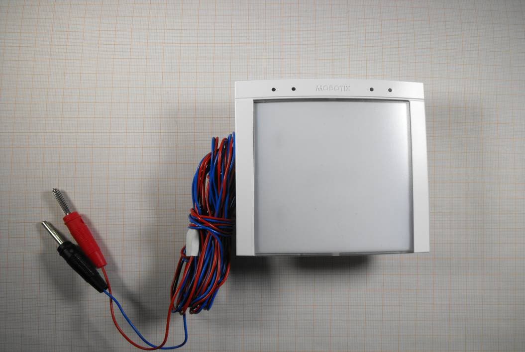
Click to zoom
Application Details
- Equipment Class
- DXX - Part 15 Low Power Communication Device Transmitter
- Date of Grant
- Jul 28, 2013
- Application Purpose
- Original Equipment
- Date of Application
- Jul 28, 2013
- Equipment Note
- RFID access control system
- Frequency Range
- 13.56000000 - 13.56000000
- Company
- MOBOTIX AG
- Country
- Germany
Documents & Files
Document Text
Text extracted from the exhibit documents filed with the FCC. Open a document above to read the original.
Users Manual
The HiRes Video Company US www.mobotix.com HiRes Video Innovations The German company MOBOTIX AG is known as the leading pioneer in network camera technology and its decentralized concept has made high-resolution video systems cost-efficient. MOBOTIX CORP • Manhattan (NY) • Phone: 888-MOBOTIX (662 6849) • [email protected] • Made in Germany BellRFID: Regulatory Notice Federal Communications Commission (FCC) and Industry Canada (IC) Notice for MX-Bell1-Core (M/N: Bell-A) (FCC ID: YYRBELLA, IC ID: 9357A-BELLA) NOTICE: This device complies with Part 15 of the FCC Rules [and with ICES-003 of Industry Canada]. Operation is subject to the following two conditions: (1) this device may not cause harmful interference, and (2) this device must accept any interference received, including interference that may cause undesired operation. NOTICE: Le présent appareil est conforme aux CNR d‘Industrie Canada applicables aux appareils radio exempts de licence. L‘exploitation est autorisée aux deux conditions suivantes: (3) l‘appareil ne doit pas produire de brouillage, et (4) l‘utilisateur de l‘appareil doit accepter tout brouillage radioélectrique subi, même si le brouillage est susceptible d‘en compromettre le fonctionnement. NOTICE: Changes or modifications made to this equipment not expressly approved by MOBOTIX AG may void the FCC authorization to operate this equipment. NOTE: This equipment has been tested and found to comply with the limits for a Class B digital device, pursuant to Part 15 of the FCC Rules. These limits are designed to provide reasonable protection against harmful interference in a residential installation. This equipment generates, uses and can radiate radio frequency energy and, if not installed and used in accordance with the instructions, may cause harmful interference to radio communications. However, there is no guarantee that interference will not occur in a particular installation. If this equipment does cause harmful interference to radio or television reception, which can be determined by turning the equipment off and on, the user is encouraged to try to correct the interference by one or more of the following measures: • Reorient or relocate the receiving antenna. • Increase the separation between the equipment and receiver. • Connect the equipment into an outlet on a circuit different from that to which the receiver is connected. • Consult the dealer or an experienced radio/TV technician for help. Radiofrequency Radiation Exposure Information: The radiated output power of the device is far below the FCC radio frequency exposure limits. Nevertheless, the device shall be used in such a manner that the potential for human contact during normal operation is minimized. Ministry of Internal Affairs and Communications Notice for MX-Bell1-Core NOTICE: • This device has been granted a designation number by Ministry of Internal Affairs and Communications • This device should not be modified (otherwise the granted designation number will be invalid) IP Video Door Station MX-Bell1-Core 31.579_US_V1_07/2013 MOBOTIX BellRFID MX-Bell1-Core (in IP Video Door Station triple frame white) RFID cards for keyless entry (1 admin card, 5 user cards) Available Bell Button Sets (Accessory) The Jones Family The Jones Family Dr. Jones, MD Cindy Jones Thomas Jones Dr. Jones, MD Cindy Jones Thomas Jones The Jones Family Dr. Jones, MD Bell Button Module with RFID Technology for up to Five Parties Cindy Jones Thomas Jones The Jones Family Dr. Jones, MD Caroline Jones Cindy Jones Thomas Jones The Jones Family Dr. Jones, MD The Jones Family Cindy Jones Thomas Jones The Jones Family Dr. Jones, MD Weatherproof (IP65) –30 to +60°C/–22 to +140°F The HiRes Video Company US www.mobotix.com HiRes Video Innovations The German company MOBOTIX AG is known as the leading pioneer in network camera technology and its decentralized concept has made high-resolution video systems cost-efficient. MOBOTIX CORP • Manhattan (NY) • Phone: 888-MOBOTIX (662 6849) • [email protected] • Made in Germany BellRFID: Conformity 2013 • Declaration of Conformity: www.mobotix.com > Support > Media Library > Certificates Copyright © MOBOTIX AG 2013 • Made in Germany • Technical information subject to change without notice. Notes • Please follow the notes on installing and operating the device in the MOBOTIX T24 System Manual (www.mobotix.com in the Support > Manuals section). • The MOBOTIX BellRFID is only to be used in the original frames of the IP Video Door Station. • Before Installing, make sure that the seal on the back of the BellRFID has been properly attached. • When inserting the module into the frame, only press at the edge, never at the center of the module. • Make sure the device is not operated outside of its operating temperature range of –30 to +60°C/–22 to +140°F. DimensionsBack Declaration of Conformity 99 mm/3.9 in 99 mm/3.9 in Cindy Jones Thomas Jones The Jones Family Dr. Jones, MD Cindy Jones Thomas Jones The Jones Family Dr. Jones, MD Hersteller Manufacturer: Fabricant : MOBOTIX AG Produkt: Product: Produit : MxBus-Modul MxBus module Module MxBus Typ: Type: Type : MX-Bell1-Core Bei bestimmungsgemäßer Verwendung erfüllt das bezeichnete Produkt die Bestimmungen gemäß Artikel 3 der R&TTE-Richtlinie 1999/5/EG. The product identified above complies with the essential requirements of article 3 of the guideline R&TTE 1999/5/EG. Le produit désigné ci-dessus est conforme aux exigences fondamentales de l’article 3 de la directive R&TTE 1999/5/EG. Angewendete harmonisierte Normen: Harmonised standards applied: Normes harmonisées : SafetyEN 60950-1:2006/A11:2009/ A1:2010/A12:2011 HealthEN 62311:2008 EMCEN 301 489-1 (V1.9.2) EN 301 489-3 (V1.4.1) ERM-SRDEN 300 330-1 (V1.7.1) EN 300 330-2 (V1.5.1) Weitere angewendete Normen: Other harmonised standards applied: Autres normes harmonisées : FCC Part 15B, Part 15C RSS 210 Item 3 of Article 44-1 of the Radio Ordinance Adresse: Address: Adresse: MOBOTIX AG Kaiserstrasse 67722 La…
Text truncated - open the document above for the full version.
Users Manual
The HiRes Video Company EN www.mobotix.com HiRes Video Innovations – Made in Germany The German company MOBOTIX AG is known as the leading pioneer in network camera technology and its decentralized concept has made high-resolution video systems cost-efficient. MOBOTIX AG • D-67722 Langmeil • Tel: +49 6302 9816-103 • Fax: +49 6302 9816-190 • [email protected] BellRFIDQuick Install Bell Button Module with RFID Technology for up to Five Parties Module for MOBOTIX IP Video Door Station, keyless entry and mailbox control, can be combined with the different bell button sets MX-Bell1-Button-F1/F2/F3/F4/05/XL1 Free-of-charge printing service on www.mobotix.com > Support • BellRFID base module with 1 admin and 5 user RFID cards • Interchangeable bell button sets (not included) • Integrated RFID technology for keyless entry • Available colors: white, silver, dark gray, black, amber • Usable with/without function button for mailbox control • Up to 60 hrs backup power supply using DoorMaster (accessory) Standard Connection: IP Video Door Station with BellRFID, InfoModule and DoorMaster Installation and Initial Operation of the BellRFID Available Bell Button Sets (for all color variants) The BellRFID module is installed in the exactly same manner as the KeypadRFID module. Make sure that you follow the steps for the different hardware scenarios of the IP Video Door Station (with/without DoorMaster) as described in the T24 System Manual Part 1 for the KeypadRFID (see below). Note: BellRFID and KeypadRFID can only be used on one MxBus with a later software version of the camera. MOBOTIX BellRFID MX-Bell1-Core (in IP Video Door Station triple frame white) I/O Terminal Sealing plug Seal MxBus terminal Back view with cover removed Door 2 6 MxBus (YSTY 0.8 mm – max. length: 50 m/55 yd) Theft protection (YSTY 0.8 mm – max. length: 50 m/55 yd) Door opener, door sensor, lock sensor (YSTY 0.8 mm – max. length: 50 m/55 yd) DoorMaster 2 RFID cards for keyless entry included (1 admin card, 5 user cards) MX-Bell1-Core 31.578_EN_V1_07/2013 You can use the blue function button at the door station to listen to new mailbox messages, record new announcements and activate/deactivate the mailbox. Visitors can leave a message even without the function button. The remaining mailbox features are easily controlled using the remote station of the door station (i.e., MOBOTIX App). Each button set contains 6 RFID cards (1 admin, 5 user cards) and pre-cut name plates made of UV-resistant paper. If required, you can replace the button sets later on – in the same base module! In order to configure the system using BellRFID, the bell buttons are replaced by a keypad insert, which is delivered with the base module. The Jones Family MX-Bell1-Button-XL1 XL bell button (no function button) MX-Bell1-Button-F1 Large bell button with function button The Jones Family MX-Bell1-Button-F2 2 medium-size bell buttons with function button The Jones Family Dr. Jones, MD MX-Bell1-Button-F4 4 small bell buttons with function button Cindy Jones Thomas Jones The Jones Family Dr. Jones, MD MX-Bell1-Button-F3 1 large, 2 small bell buttons with function button Cindy Jones Thomas Jones Dr. Jones, MD MX-Bell1-Button-05 5 small bell buttons (no function button) Caroline Jones Cindy Jones Thomas Jones The Jones Family Dr. Jones, MD Before starting the installation and initial operation, you should download part 1 and 2 of the T24 System Manual from the MOBOTIX website (www.mobotix.com > Support > Manuals). If the installation of the IP Video Door Station with BellRFID is not followed by the initial operation right away, MOBOTIX recommends to remove the keypad insert and to insert the button set before starting the installation. This way, the soft rubber surface of the BellRFID base module is well protected until the module is brought into service (bell buttons are then replaced by the keypad insert). Note that the base module is weatherproof even without the bell buttons. When replacing the button set or exchanging name plates, you need to remove the module from the frame of the IP Video Door Station. Use the blue MOBOTIX key for unlocking the module. Make sure that you are activating the mechanical thef t protection with the red turning knob in the door station frame only af ter you have finished the initial operation (see the Section «Mechanical Anti-Theft Protection Lock» in the T24 System Manual Part 1). In order to avoid having to remove the module and install it again, you should insert the proper name plates before starting the initial operation. Use our free-of-charge printing service on www.mobotix.com in the Support section! Or use the supplied name plates made from sturdy specialty paper and write the names using a UV-resistant marker. Available Bell Button Sets (Accessory) The Jones Family The Jones Family Dr. Jones, MD Cindy Jones Thomas Jones Dr. Jones, MD Cindy Jones Thomas Jones The Jones Family Dr. Jones, MD Cindy Jones Thomas Jones The Jones Family Dr. Jones, MD Caroline Jones Cindy Jones Thomas Jones The Jones Family Dr. Jones, MD The Jones Family 1. Insert the Name Plate(s) Remove the silicon insert from the button. Recommendation: Take a suitable tool without a sharp blade, cautiously insert it into the slot, gently press inward and lift the tool as shown. Insert the labeled or printed name plate as shown (the arrows at the side are pointing upwards later on). Place the silicon insert on top of the name plate, push it into the frame at the top and at the bottom of the center, then push its sides into the frame. Make sure that the silicon insert fits flush into the frame of the bell button as shown to protect the name plate against humidity. 2. Insert the Module into the Door Station You can use the BellRFID module as an alternative to the KeypadRFID (but not yet side-by-side) in the frame of an IP Video Door Station. For installing and wiring the module, follow the same steps as for the KeypadRFID. Follow the description in the Section «…
Text truncated - open the document above for the full version.
External Photos
Test report no.: 1-5412/12-01-05-C_AnnexA 2013-07-12 Page 1 of 5 Annex A This test report annex is electronically signed and valid without handwriting signature. For verification of the electronic signatures, the public keys can be requested at the testing laboratory. Test report annex authorised: Stefan Bös Senior Testing Manager Test report no.: 1-5412/12-01-05-C_AnnexA 2013-07-12 Page 2 of 5 External photos of the EUT Photo documentation: Photo 1: Photo 2: Test report no.: 1-5412/12-01-05-C_AnnexA 2013-07-12 Page 3 of 5 Photo 3: Photo 4: Test report no.: 1-5412/12-01-05-C_AnnexA 2013-07-12 Page 4 of 5 Photo 5: Photo 6: Test report no.: 1-5412/12-01-05-C_AnnexA 2013-07-12 Page 5 of 5 Document history Version Applied changes Date of release 1.0 Initial release 2013-07-12
ID Label/Location Info
1 1 2 2 3 3 4 4 5 5 6 6 7 7 8 8 D CC BB AA MOBOTIX:AG Kaiserstrasse 67722:Langmeil www.mobotix.com Germany Bell1-EXT 1 22.04.2013 Size Drawn0byDate Rev A4 Title MarceloZimmer Tel::+49:6302:9816:0 Fax.::+49:6302:9816:190 MOBOTIX .com X Security0Vision0Systems mmUnit1:1Scale LabeloLocation 総務省指定 第 XX-XXXXX 号 MIC KS 1234567o|oMOBOTIXoAGo|oMX-Bell1-EXT 1234567 400mm 60mm 1234567o|oMOBOTIXoAGo|oMX-Bell1-EXT 1234567 400mm 60mm FCC-ID:oYYRBELLAIC-ID:o9357A-BELLA M/N:oBell-A FCC-ID:oYYRBELLA IC-ID:o9357A-BELLA M/N:oBell-A
Internal Photos
Test report no.: 1-5412/12-01-05-C_AnnexB 2013-07-12 Page 1 of 4 Annex B This test report annex is electronically signed and valid without handwriting signature. For verification of the electronic signatures, the public keys can be requested at the testing laboratory. Test report annex authorised: Stefan Bös Senior Testing Manager Test report no.: 1-5412/12-01-05-C_AnnexB 2013-07-12 Page 2 of 4 Internal photos of the EUT Photo documentation: Photo 1: Photo 2: Test report no.: 1-5412/12-01-05-C_AnnexB 2013-07-12 Page 3 of 4 Photo 3: Test report no.: 1-5412/12-01-05-C_AnnexB 2013-07-12 Page 4 of 4 Document history Version Applied changes Date of release 1.0 Initial release 2013-07-12
Test Report
2013-07-12 Page 1 of 25 TEST REPORT Test report no.: 1-5412/12-01-05-C Testing laboratory Applicant CETECOM ICT Services GmbH Untertuerkheimer Strasse 6 – 10 66117 Saarbruecken / Germany Phone: + 49 681 5 98 - 0 Fax: + 49 681 5 98 - 9075 Internet: http://www.cetecom.com e-mail: [email protected] Accredited Testing Laboratory: The testing laboratory (area of testing) is accredited according to DIN EN ISO/IEC 17025 (2005) by the Deutsche Akkreditierungsstelle GmbH (DAkkS) The accreditation is valid for the scope of testing procedures as stated in the accreditation certificate with the registration number: D-PL-12076-01-01 Area of Testing: Radio/Satellite Communications Mobotix AG Kaiserstr. 67722 Winnweiler / GERMANY Phone: +49 6302 9816-0 Fax: Contact: Thomas Kern e-mail: [email protected] Phone: +49 6302-9816-0 Manufacturer Mobotix AG Kaiserstr. 67722 Winnweiler / GERMANY Test standard/s 47 CFR Part 15 Title 47 of the Code of Federal Regulations; Chapter I Part 15 - Radio frequency devices RSS - 210 Issue 8 Spectrum Management and Telecommunications - Radio Standards Specification Low-power Licence-exempt Radiocommunication Devices (All Frequency Bands): Category I Equipment For further applied test standards please refer to section 3 of this test report. Test Item Kind of test item: RFID Reader Model name: Bell-A FCC ID: YYRBELLA IC: 9357A-BELLA Frequency: 13.56 MHz Technology tested: RFID Antenna: Integrated loop antenna Power Supply: 48V DC by external power supply Temperature Range: -20°C to +55°C This test report is electronically signed and valid without handwriting signature. For verification of the electronic signatures, the public keys can be requested at the testing laboratory. Test report authorised: Test performed: p.o. Christoph Schneider Tobias Wittenmeier Expert Expert Test report no.: 1-5412/12-01-05-C 2013-07-12 Page 2 of 25 1 Table of contents 1 Table of contents ............................................................................................................................................ 2 2 General information ....................................................................................................................................... 3 2.1 Notes and disclaimer .......................................................................................................................... 3 2.2 Application details ............................................................................................................................... 3 3 Test standard/s ............................................................................................................................................... 3 4 Test environment ............................................................................................................................................ 4 5 Test item .......................................................................................................................................................... 4 6 Test laboratories sub-contracted ................................................................................................................. 4 7 Additional information ................................................................................................................................... 4 8 Summary of measurement results ............................................................................................................... 5 9 RF measurements .......................................................................................................................................... 6 9.1 Description of test setup .................................................................................................................... 6 9.1.1 Radiated measurements............................................................................................................. 6 9.2 AC conducted ...................................................................................................................................... 8 9.3 Conducted measurements ................................................................................................................. 9 9.4 Additional comments .......................................................................................................................... 9 9.5 RSP100 test report cover sheet / performance test data .............................................................. 10 10 Measurement results ............................................................................................................................ 11 10.1 Timing of the transmitter ............................................................................................................... 11 10.2 Field strength of the fundamental ................................................................................................ 12 10.3 99 % emission bandwidth ............................................................................................................. 13 10.4 Field strength of the harmonics and spurious ........................................................................... 14 10.5 Frequency tolerance ...................................................................................................................... 19 10.6 Conducted emissions < 30 MHz (AC line conducted) ................................................................ 20 11 Test equipment and ancillaries used for tests ................................................................................... 22 12 Observations ......................................................................................................................................... 23 Annex A Document history .......................................................................................................................... 24 Annex B Further information .........................................................…
Text truncated - open the document above for the full version.
Test Setup Photos
Test report no.: 1-5412/12-01-05-C_AnnexC 2013-07-12 Page 1 of 6 Annex C This test report annex is electronically signed and valid without handwriting signature. For verification of the electronic signatures, the public keys can be requested at the testing laboratory. Test report annex authorised: Stefan Bös Senior Testing Manager Test report no.: 1-5412/12-01-05-C_AnnexC 2013-07-12 Page 2 of 6 Photographs of the test setup Photo documentation: Photo 1: Photo 2: Test report no.: 1-5412/12-01-05-C_AnnexC 2013-07-12 Page 3 of 6 Photo 3: Photo 4: Test report no.: 1-5412/12-01-05-C_AnnexC 2013-07-12 Page 4 of 6 Photo 5: Photo 6: Test report no.: 1-5412/12-01-05-C_AnnexC 2013-07-12 Page 5 of 6 Photo 7 Test report no.: 1-5412/12-01-05-C_AnnexC 2013-07-12 Page 6 of 6 Document history Version Applied changes Date of release 1.0 Initial release 2013-07-12
Contact Information
Applicant
Christoph Denzer
Test Firm
cetecom advanced GmbHGerald Schmidt
Technical Specifications
| # | Rule Parts | Frequency Range | Power Output |
|---|---|---|---|
| 1 | 15C | 13.56 MHz - 13.56 MHz | - |
Other Applications from MOBOTIX AG
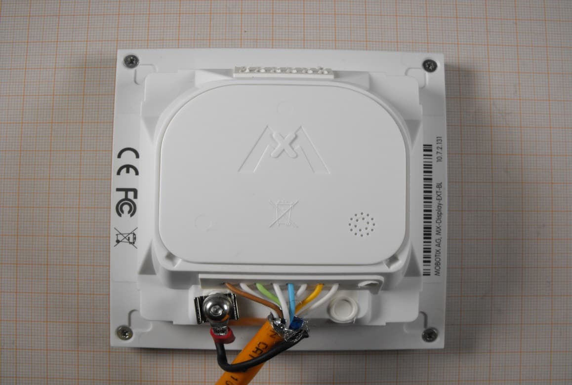
YYRDISPA
Dec 07, 2014MX-Display
Equipment Class
DXX - Part 15 Low Power Communication Device Transmitter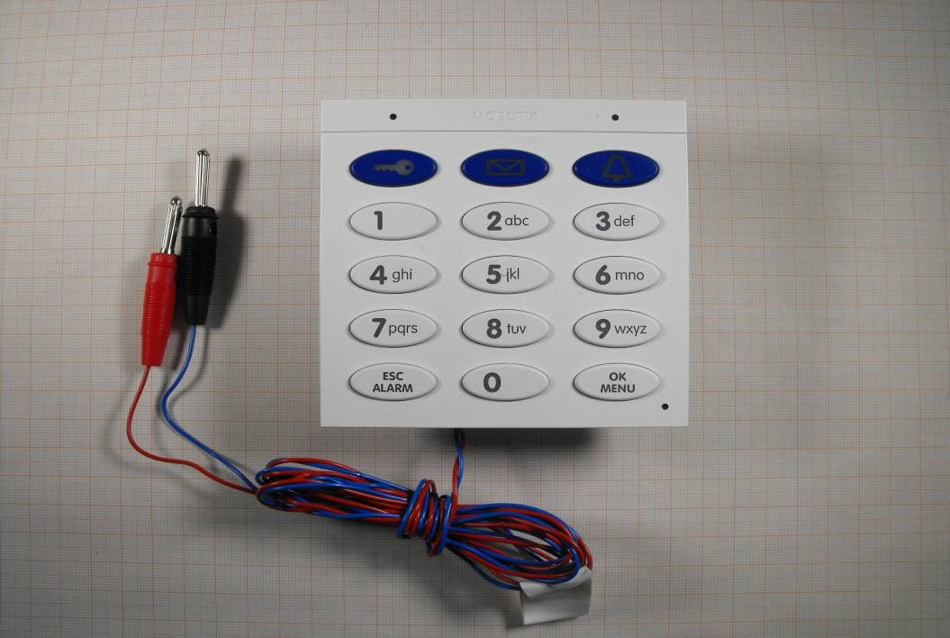
YYRKPADB
Jul 28, 2013RFID access control system
Equipment Class
DXX - Part 15 Low Power Communication Device Transmitter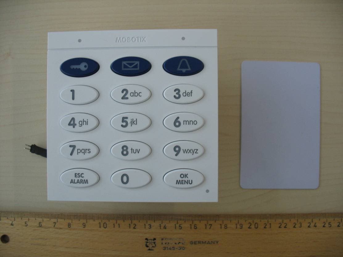
YYRMXKP01
Apr 20, 2011Access control system
Equipment Class
DXX - Part 15 Low Power Communication Device Transmitter