YZHFTRHCLRF0217 key magic light strip belt controller
Raffel Systems, LLC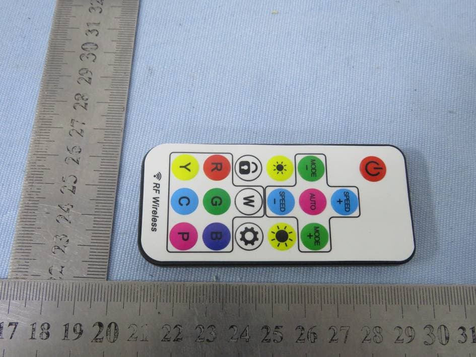
Click to zoom
Application Details
- Equipment Class
- DSC - Part 15 Security/Remote Control Transmitter
- Date of Grant
- Dec 17, 2020
- Application Purpose
- Original Equipment
- Date of Application
- Dec 17, 2020
- Equipment Note
- 17 key magic light strip belt controller
- Frequency Range
- 433.92000000 - 433.92000000
- Company
- Raffel Systems, LLC
- Country
- United States
Documents & Files
Document Text
Text extracted from the exhibit documents filed with the FCC. Open a document above to read the original.
Users Manual
Product Instructions Safety warning In order to ensure the integrity and safety of the product, please follow the warnings and reminders in this manual. Be careful! Please read the safety precautions carefully: 1. During installation, try to avoid in the minefield, strong magnetic field and high pressure area; 2. Ensure that the wiring is correct and firm, so as to avoid short circuit damaging components and triggering fire accidents; 3. Please install the controller in a well ventilated place to ensure the appropriate ambient temperature; 4. Please check whether the input power supply voltage of the controller meets the product requirements, and whether the definition of the positive and negative poles of the power supply is consistent with the product; 5. Live wiring is prohibited. After checking and confirming that the wiring is correct, check that there is no short circuit in the power on; 6. If there is any problem, please do not repair it without permission. If in doubt, please contact the supplier. Product introduction The 17 key magic light strip controller uses the advanced microcomputer control IC and the most advanced PWM (pulse width modulation) control technology, which is used to control various lamps and lanterns with LED as the light source. It can control most of the three wire led magic lighting products on the market. The 17 key magic light strip controller has 358 function mode selection, which can send control commands through RF remote control within effective distance to control the function change, speed adjustment, brightness adjustment, static color selection and various dynamic light change effects of LED light belt. The 17 key magic light strip controller has power down holding function. In case of accidental power failure during use, the previous data (mode and speed) will be displayed in the next startup. Performance parameter ●Product Name: 17 key magic light belt controller ●Model:FTR HC L RF 02 ●FCC ID: YZHFTRHCLRF02 ●Working temperature :-10~50°C ●Input voltage :DC5V; ●Static power consumption:< 1W; ●Output power: < 40W ●Frequency:433.92 MHz ●Speed selection: level 8 ●Brightness adjustment: 8 levels ●Change mode: 358 modes ●Remote control distance: more than 10 meters; ●Remote control battery type:CR2025; Overall Dimension Controller Strip dimension Controller dimension Schematic diagram of product connection Remote control key name and function description FCC Statement This device complies with Part 15 of the FCC Rules. Operation is subject to the following two conditions: (1)This device may not cause harmful interference. (2)This device must accept any interference received, including interference that may cause undesired operation. Changes or modifications not expressly approved by the party responsible for compliance could void the user’s authority to operate the equipment. Note: This equipment has been tested and found to comply with the limits for a class B digital device, pursuant to Part 15 of the FCC Rules. These limits are designed to provide reasonable protection against harmful interference in a residential installation. This equipment generates uses and can radiate radio frequence energy and, if not installed and used in accordance with the instructions, may cause harmful interference to radio communications. However, there is no guarantee that interference will not accor in a particular installation. if this equipmemt does cause harmful interference to radio or television reception, which can be determined by turning the equipment off and on, the user is encouraged to try to correct the interference by one or more of the following measures: • Reorient or relocate the receiving antenna. • Increase the separation between the equipment and receiver. • Connect the equipment into an autlet on a circuit different from that to which the receiver is connectec. • Consult the dealer or an experienced technician for help. FCC Radiation Exposure Statement The device has been evaluated to meet general RF exposure requirement. The device can be used in portable exposure condition without restriction.
External Photos
Report No.: NTC2011333FV00 FCC ID: YZHFTRHCLRF02 Page 3 of 6 External photos Report No.: NTC2011333FV00 FCC ID: YZHFTRHCLRF02 Page 4 of 6
ID Label/Location Info
SILVER POLYPROPYLENE LABEL BLACK TEXT READS,L*W:34*16 Label FCC ID:YZHFTRHCLRF02 MOD#FTR HC L RF 02 MADE IN CHINA
Internal Photos
Report No.: NTC2011333FV00 FCC ID: YZHFTRHCLRF02 Page 5 of 6 Internal photos Report No.: NTC2011333FV00 FCC ID: YZHFTRHCLRF02 Page 6 of 6 RF Chip RF Antenna
Operational Description
Raffel Systems, LLC Declaration concerning Antenna Specification It is hereby declared that the product Model No.: FTR HC L RF 02 FCC ID: YZHFTRHCLRF02 fulfills the requirement in FCC test relating to the antenna type. The device specified above confirms to the FCC recommendations for internal antenna type(s) described below: Model No. of antenna: PCB Antenna Type of antenna: permanently attached (PCB antenna) Gain of the antenna: 0 dBi Frequency range: 433.92 MHz The mounting of the antenna is fixed to the radio module and no other antenna should be used. Company name: Raffel Systems, LLC Address: N112 W14600 Mequon Road City: Germantown Wisconsin ZIP / Postal code: 53022 Country: United States Place: Jason Zhang Date: 2020-12-17 Signature:
RF Exposure Info
Dongguan Nore Testing Center Co., Ltd. Report No.: NTC2011333F-1 FCC ID: YZHFTRHCHRF02 RF EXPOSURE EVALUATION EUT Specification EUT 17 key magic light strip belt controller Model Name FTR HC L RF 02 Frequency band (Operating) WLAN: 2.412GHz ~ 2.462GHz WLAN: 5.18GHz ~ 5.32GHz / 5.50GHz ~ 5.70GHz WLAN: 5.745GHz ~ 5825GHz Others(433.92MHz) Device category Portable (<20cm separation) Mobile (>20cm separation) Others ___ Antenna diversity Single antenna Multiple antennas Tx diversity Rx diversity Tx/Rx diversity Max. output power 71.35dBuV/m (-23.91dBm)( 0.004mW) Antenna gain 0dBi Evaluation applied MPE Evaluation SAR Evaluation Dongguan Nore Testing Center Co., Ltd. Report No.: NTC2011333F-1 FCC ID: YZHFTRHCHRF02 Standard Requirement Portable Device According to §15.247(i) and §1.1307b(1), systems operating under the provisions of this section shall be operated in a manner that ensures that the public is not exposed to radio frequency energy levels in excess of the Commission’s guidelines. See KDB 447498 D01 General RF Exposure Guidance v05, section 4.3.1. The 1-g and 10-g SAR test exclusion thresholds for 100 MHz to 6 GHz at test separation distances ≤ 50 mm are determined by: [(max. power of channel, including tune-up tolerance, mW)/(min. test separation distance, mm)] ·[√f(GHz)] ≤ 3.0 for 1-g SAR and ≤ 7.5 for 10-g extremity SAR, 16 where ·f(GHz) is the RF channel transmit frequency in GHz ·Power and distance are rounded to the nearest mW and mm before calculation17 ·The result is rounded to one decimal place for comparison The test exclusions are applicable only when the minimum test separation distance is ≤ 50 mm and for transmission frequencies between 100 MHz and 6 GHz. When the minimum test separation distance is < 5 mm, a distance of 5 mm is applied to determine SAR test exclusion. Measurement Result Channel Frequency (MHz) Max Output power (dBm) Max Output power (mW) Calculation Value (Note 1) Threshold Value 433.92 -23.91 0.004 5.27e-4 3.0 EIRP=E-104.8+20logD=71.35-104.8+20log3=-23.91dBm Note 1: Calculation Value =[(max. power of channel, mW)/(min. test separation distance, mm)] ·[√f(GHz)]. Fox example: 0.004/5*√0.43392=5.27e-4≤ 3.0 According to KDB447498 D01 V05, threshold at which no SAR required is ≤3.0 for 1-g SAR, separation distance is 5mm, and no simultaneous SAR measurement is required. The SAR measurement is not necessary.
Test Report
Report No.: NTC2011333FV00 FCC ID: YZHFTRHCLRF02 Page 2 of 29 Table of Contents 1. Summary of Test Result ...................................................................................................................................... 4 2. General Description of EUT ................................................................................................................................ 5 3. Test Channels and Modes Detail ........................................................................................................................ 7 4. Configuration of EUT ........................................................................................................................................... 7 5. Modification of EUT ............................................................................................................................................. 7 6. Description of Support Device ............................................................................................................................. 7 7. Test Facility and Location ................................................................................................................................... 8 8. Applicable Standards and References ................................................................................................................ 9 9. Deviations and Abnormalities from Standard Conditions ................................................................................... 9 10. Test Conditions ................................................................................................................................................. 9 11. Measurement Uncertainty ............................................................................................................................... 10 12. Sample Calculations ....................................................................................................................................... 11 13. Duty Cycle ....................................................................................................................................................... 12 14. Test Items and Results ................................................................................................................................... 13 14.1 Conducted Emissions Measurement ............................................................................................................ 13 14.2 Radiated Spurious Emissions Measurement ................................................................................................ 15 14.3 20dB Occupied Bandwidth ............................................................................................................................ 24 14.4 Transmission Time ........................................................................................................................................ 26 14.5 Antenna Requirement ................................................................................................................................... 28 15. Test Equipment list .......................................................................................................................................... 29 Report No.: NTC2011333FV00 FCC ID: YZHFTRHCLRF02 Page 3 of 29 Revision History Report Number Description Issued Date NTC2011333FV00 Initial Issue 2020-12-03 Report No.: NTC2011333FV00 FCC ID: YZHFTRHCLRF02 Page 4 of 29 1. Summary of Test Result FCC Rules Description of Test Result Remarks §15.207 (a) AC Power Line Conducted Emission N/A see note 2 --- §15.231(b) & 15.209 Radiated Spurious Emission PASS --- §15.231(c) 20 dB Occupied bandwidth PASS --- §15.231(a) Transmission time PASS --- §15.203 Antenna Requirement PASS --- Note: 1. The EUT has been tested as an independent unit. And continual transmitting in maximum power (New batteries were used during test) 2. AC Power Conducted Emission is not applicable due to the EUT only can be powered by battery. Report No.: NTC2011333FV00 FCC ID: YZHFTRHCLRF02 Page 5 of 29 2. General Description of EUT Product Information Product Name: 17 key magic light strip belt controller Main Model Name: FTR HC L RF 02 Additional Model Name: N/A Model Difference: N/A P/N: RAFFEL202004 Brand Name: Raffel Systems Hardware Version: V01 Software Version: V01 Rating: DC 3V(Button battery CR2032) Classification: Class B Typical arrangement: Table-top I/O Port: N/A Accessories Information Adapter: N/A Cable: N/A Other: N/A Additional Information Note: N/A Remark: All the information above are provided by the manufacturer. More detailed feature of the EUT please refers to the user manual. Report No.: NTC2011333FV00 FCC ID: YZHFTRHCLRF02 Page 6 of 29 Technical Specification (433MHz Transmitter) Declaring the Frequency: 433.92MHz Modulation Type: ASK Antenna Type: PCB antenna Antenna Gain: 0 dBi (Declared by manufacturer) Number of Channels: 1 Report No.: NTC2011333FV00 FCC ID: YZHFTRHCLRF02 Page 7 of 29 3. Test Channels and Modes Detail Mode Test Frequency (MHz) Modulation Data Rate (Mbps) 1 TX 433.92MHz ASK ---- Note: TX mode means that the EUT was programmed to be in continuously transmitting mode. 4. Configuration of EUT TX Mode 5. Modification of EUT No modifications are made to the EUT during all test items. 6. Description of Support Device The EUT has been tested as an independent unit together with other necessary accessories or support units. The following support units or accessories were used to form a representative test configuration during the tests. No. Equipment Brand M/N S/N Cable Specification Remarks 1. --- --- --- --- --- --- EUT Report No.: NTC2011333FV00 FCC ID: YZHFTRHCLRF02 Page 8 of 29 7. Test Facility and Location Test Site : Dongguan Nore Testing Center Co., Ltd. (Dongguan NTC Co., Ltd.) Accreditations and Authorizations : The Laboratory has been assessed and proved to be in compliance with CNAS/CL01 Listed by CNAS, August 13,…
Text truncated - open the document above for the full version.
Test Setup Photos
Report No.: NTC2011333FV00 FCC ID: YZHFTRHCLRF02 Page 1 of 6 Test Photo Radiated emission (Below 30MHz) Radiated emission (30-1000MHz) Report No.: NTC2011333FV00 FCC ID: YZHFTRHCLRF02 Page 2 of 6 Radiated emission (Above 1000MHz)
Contact Information
Applicant
Edward A Nowak(Electrical Engineer)
Test Firm
Dongguan NTC CO., Ltd.Jees Hong
[email protected]+86-769-22022444
Technical Specifications
| # | Rule Parts | Frequency Range | Power Output |
|---|---|---|---|
| 1 | 15.231 | 433.92 MHz - 433.92 MHz | - |
Other Applications from Raffel Systems, LLC
YZHMDLMPP1501
Jun 17, 2026MPP emission module
Equipment Class
DCD - Part 15 Low Power Transmitter Below 1705 kHz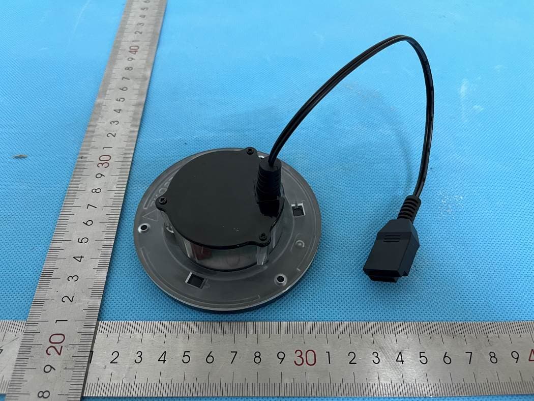
YZHWCPBA01
May 07, 2024Embedded Wireless Charger
Equipment Class
DCD - Part 15 Low Power Transmitter Below 1705 kHz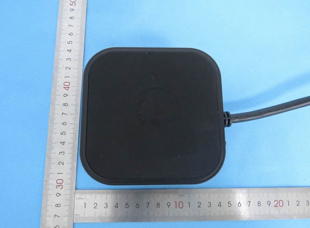
YZHACCPS2QU201
Mar 31, 2024Power Strip
Equipment Class
DCD - Part 15 Low Power Transmitter Below 1705 kHz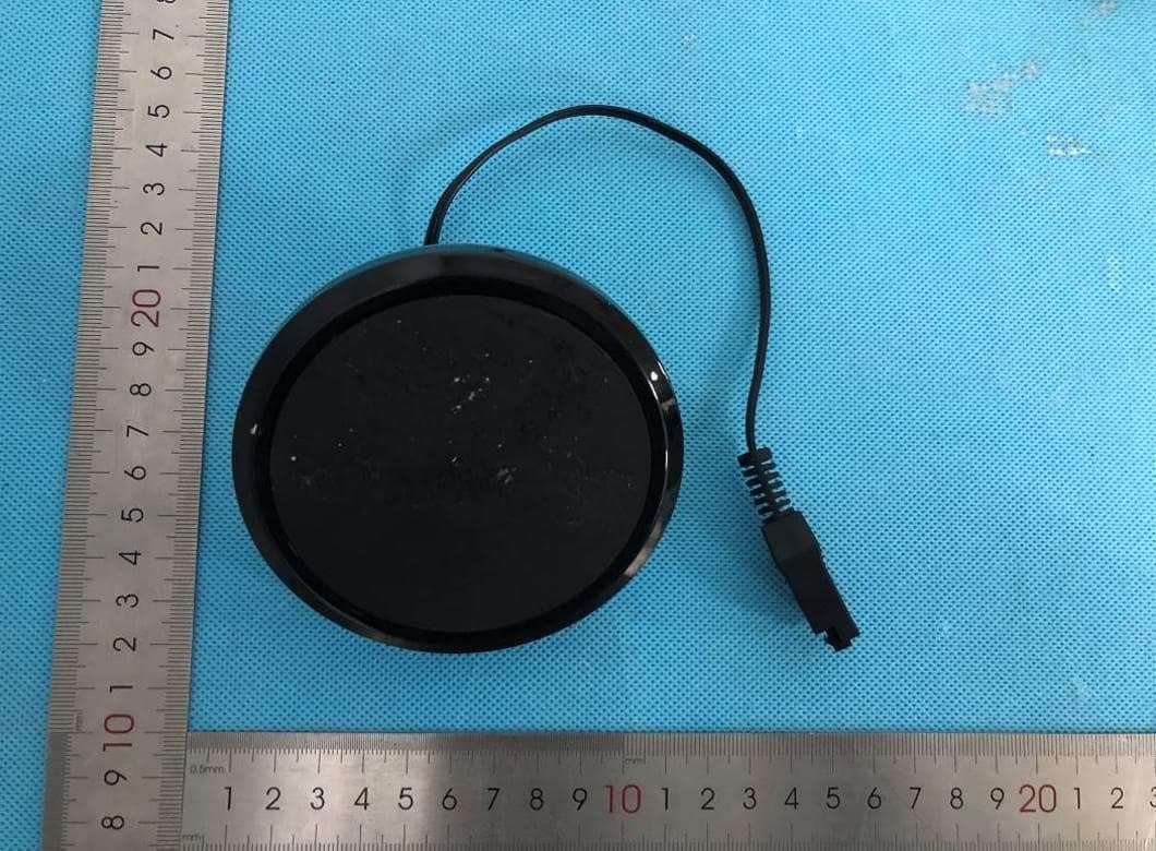
YZHWCPXXX01
Jun 05, 2023Embedded wireless charger
Equipment Class
DCD - Part 15 Low Power Transmitter Below 1705 kHzYZHFTRHCLRF01
Dec 17, 202017 key RGB colorful light belt controller
Equipment Class
DSC - Part 15 Security/Remote Control Transmitter