YZHWCPBL03Wireless Distance Charger
Raffel Systems, LLCApplication Details
- Equipment Class
- DCD - Part 15 Low Power Transmitter Below 1705 kHz
- Date of Grant
- Feb 25, 2020
- Application Purpose
- Original Equipment
- Date of Application
- Feb 25, 2020
- Equipment Note
- Wireless Distance Charger
- Frequency Range
- 0.11050000 - 0.13000000
- Company
- Raffel Systems, LLC
- Country
- United States
Documents & Files
Document Text
Text extracted from the exhibit documents filed with the FCC. Open a document above to read the original.
Users Manual
Product Instruction For your safety, please read this manual carefully before using this product. 一、 In order to protect you from injury and property damage, we clearly explain what you should follow: A) Warning! It may cause serious injuries or even casualties.People should consult the doctor before using implantable medical devices (such as using pacemaker).Please install your equipment 50 centimeters away from this product because it may influence the operation of implantable medical device. B) Attention! It may cause fever, fire and electric shock. 1) Do not put the product in water or other liquids, avoid water into the product; 2) Do not touch the AC adapter with wet hands to ensure the safety and integrity of the adapter 3) Do not let dust accumulate on this product and adapter 4) Do not use this product under the temperature of -10°C——40°C; 5) Do not use it in the places of direct sunlight or high temperature; 6) Do not charge too close to magnetic sheets, magnetic recording media and precision instruments 7) Do not decompose and transform this product 8) Do not put any metal objects between the distance charging transmitting board and the charging mobile phone; 9) When using plugs and other connections, do not exceed the rated value 10) When using, please make sure that you have connected the AC adapter correctly to avoid any damage. Unplug AC adapter from plug when stopping using it. 11) Do not use travel converters 12) Do not let your children use it until they know how to use it. 二、 Charging method of distance charging Diagram for using and installing: ①—— Mobile phone ②——Marble, glass, wood, plastic and other non-metallic tabletop ③——Wireless distance charger ④ ——Adapter 1) Connect the product to an adapter that outputs 24-31Vdc or any device with an output voltage of 24-31Vdc; 2) If the distance charging product detects that there is no equipment to be charged in the charging area, the product will be on standby. 3) Put the device (mobile phone) to be charged directly in the charging area of the product, the device enter the charging state, and the blue light is on; 4) After charging, the product is standby, the blue light is on, then take it away. 5) If there is a metal some-like in the charging area (the center of the coil), blue and green light flicker alternately and will disconnect distance charging to protect equipment 三、 Product parameter: 1)Product model: WCP BL 03 series Distance charging products 2)Product name: Wireless distance charger 3)Dimension: Length is 142mm, Width is 94.5mm, and height is 14.2mm 4)Main function: distance charging launcher 5)Product application: All distance charging devices under QI standard 7)Charging type: One-to-one charging in corresponding area 8)Input voltage: 24-31Vdc 9)Launch distance: 15-30mm 10)Charging power: 10W(MAX) 11)Charging way: Induction mode 12)Working frequency: 110.5—130KHz FCC Statement 1. This device complies with Part 15 of the FCC Rules. Operation is subject to the following two conditions: (1)This device may not cause harmful interference. (2)This device must accept any interference received, including interference that may cause undesired operation. 2. Changes or modifications not expressly approved by the party responsible for compliance could void the user’s authority to operate the equipment. Note:This equipment has been tested and found to comply with the limits for a class B digital device,pursuant to Part 15 of the FCC Rules. These limits are designed to provide reasonable protection against harmful interference in a residential installation. This equipment generates uses and can radiate radio frequence energy and,if not installed and used in accordance with the instructions,may cause harmful interference to radio communications.However,there is no guarantee that interference will not accor in a particular installation.if this equipmemt does cause harmful interference to radio or television reception,which can be determined by turning the equipment off and on,the user is encouraged to try to correct the interference by one or more of the following measures: • Reorient or relocate the receiving antenna. • Increase the separation between the equipment and receiver. • Connect the equipment into an autlet on a circuit different from that to which the receiver is connectec. • Consult the dealer or an experienced technician for help. This equipment should be installed and operated with a minumum distance of 20 cm between the device and your body.
External Photos
FCC ID: YZHWCPBL03 External photo FCC ID: YZHWCPBL03 FCC ID: YZHWCPBL03
ID Label/Location Info
LABEL LABEL MOD: WCP BL 03 PO # ______DATE CODE______ FCC ID:YZHWCPBL03 INPUT:24-31Vdc OUTPUT:10W Max PATENT PENDING MADE IN CHINA This device complies with Part 15 of the FCC Rules. Operation is subject to the following two conditions: (1)This device may not cause harmful interference. (2)This device must accept any interference received, including interference that may cause undesired operation. MOD: WCP BL 03 PO # ______DATE CODE______ FCC ID:YZHWCPBL03 INPUT:24-31Vdc OUTPUT:10W Max PATENT PENDING MADE IN CHINA This device complies with Part 15 of the FCC Rules. Operation is subject to the following two conditions: (1)This device may not cause harmful interference. (2)This device must accept any interference received, including interference that may cause undesired operation. Label & Location
Internal Photos
FCC ID: YZHWCPBL03 Internal photo RF Antenna FCC ID: YZHWCPBL03 FCC ID: YZHWCPBL03
Operational Description
Raffel Systems, LLC Declaration concerning Antenna Specification It is hereby declared that the product Model No.: WCP BL 03, WCP BL 03-XX FCC ID: YZHWCPBL03 fulfills the requirement in FCC test relating to the antenna type. The device specified above confirms to the FCC recommendations for internal antenna type(s) described below: Model No. of antenna: Coil Antenna Type of antenna: permanently attached (coil antenna) Gain of the antenna: 0 dBi Frequency range: 110.5-130 KHz The mounting of the antenna is fixed to the radio module and no other antenna should be used. Company name: Raffel Systems, LLC Address: N112 W14600 Mequon Road City: Germantown Wisconsin ZIP / Postal code: 53022 Country: United States Place: Jason Zhang Date: 2020-02-24 Signature:
RF Exposure Info
Dongguan Nore Testing Center Co., Ltd. Report No.: NTC2001096F-1 FCC ID: YZHWCPBL03 Page 1 of 8 RF EXPOSURE REPORT The device described below is tested by Dongguan Nore Testing Center Co., Ltd. to determine the maximum emission levels emanating from the device, the severe levels which the device can endure and E.U.T.’s performance criterion. The test results, data evaluation, test procedures, and equipment of configurations shown in this report were made in accordance with the procedures in ANSI C63.10(2013). Applicant / Manufacturer : Raffel Systems, LLC Address : N112 W14600 Mequon Road Germantown Wisconsin United States Factory 1 : FORTRESS ELECTRONICS(XIAMEN)CO.,LTD Address 1 : East of the fifth floor, 181 banqiao road, jimei district, Xiamen, Fujian, China Factory 2 : ZHUHE (Xiamen) New Energy Technology Co., Ltd. Address 2 : Unit 401 NO.32 Xiangyue Road,Torch Hi-Tech Industrial Development E.U.T. : Wireless Distance Charger Brand Name : Raffel Systems Model No. : WCP BL 03, WCP BL 03-XX (For model difference refer to section 1) FCC ID : YZHWCPBL03 Measurement Standard : FCC PART 15 Subpart C Date of Receiver : January 14, 2020 Date of Test : January 14, 2020 to January 18, 2020 Date of Report : February 22, 2020 In the configuration tested, the EUT complied with the standards specified above. This test report is for the customer shown above and their specific product only. This report applies to above tested sample only and shall not be reproduced in part without written approval of Dongguan Nore Testing Center Co., Ltd. TEL: +86-769-22022444 FAX: +86-769-22022799 Web: www.ntc-c.com Address: Building D, Gaosheng Science and Technology park, Hongtu road, Nancheng district, Dongguan city, Guangdong province, China Dongguan Nore Testing Center Co., Ltd. Report No.: NTC2001096F-1 FCC ID: YZHWCPBL03 Page 2 of 8 1. GENERAL INFORMATION 1.1 Product Description for Equipment under Test Product name : Wireless Distance Charger Main model : WCP BL 03 Additional model : WCP BL 03-XX (The XX will use number to show, and each Y's range from 0 to 9 is for different DC input cord's length and different connector type and size.) Model difference : These models have the same circuit schematic, construction, PCB Layout and critical components. The difference in model number, DC input cord's length and different connector type and size due to trading purpose. Power Supply : Input: DC 24-31V Output: DC 9V 1A 10W Max Test voltage : AC 120V 60Hz adapter input. Adapter : N/A Cable : N/A Software version : V1.0 Hardware version : V1.0 Note : N/A Remark : According to the model difference, all tests were performed on model WCP BL 03. Frequency Range : 110.5-130KHz Test frequency : 119K Remark : N/A Dongguan Nore Testing Center Co., Ltd. Report No.: NTC2001096F-1 FCC ID: YZHWCPBL03 Page 3 of 8 1.2 Related Submittal(s) / Grant (s) This submittal(s) (test report) is intended for FCC ID: YZHWCPBL03 filing to comply with FCC Part 15 (2017), Subpart C Rule. 1.3 Test Facility and Location Site Description EMC Lab : Listed by CNAS, August 13, 2018 The certificate is valid until August 13, 2024 The Laboratory has been assessed and proved to be in compliance with CNAS/CL01 The Certificate Registration Number is L5795. Listed by A2LA, November 01, 2017 The certificate is valid until December 31, 2021 The Laboratory has been assessed and proved to be in compliance with ISO17025 The Certificate Registration Number is 4429.01 Listed by FCC, November 06, 2017 The Designation Number is CN1214 Test Firm Registration Number: 907417 Listed by Industry Canada, June 08, 2017 The Certificate Registration Number. Is 46405-9743 Name of Firm : Dongguan Nore Testing Center Co., Ltd. (Dongguan NTC Co., Ltd.) Site Location : Building D, Gaosheng Science & Technology Park, Zhouxi Longxi Road, Nancheng District, Dongguan City, Guangdong Province, China Dongguan Nore Testing Center Co., Ltd. Report No.: NTC2001096F-1 FCC ID: YZHWCPBL03 Page 4 of 8 2. Measurement Uncertainty Measurement Uncertainty for a Lecel of Confidedce of 95%, U=2xUc(y) Radiated emission(9KHz~150KHz) ±3.50dB Radiated emission(150KHz~30MHz) ±3.50dB Radiated emission(30MHz~1GHz) ±3.70dB Dongguan Nore Testing Center Co., Ltd. Report No.: NTC2001096F-1 FCC ID: YZHWCPBL03 Page 5 of 8 3. Method of measurement 3.1 Applicable standard According to 1.1307(b)(1), system operating under the provisions of this section shall be operated in amnner that ensures that the public is not exposed to radio frequency energy level in excess of the commission's guidelines. According to 1.1310 and 2.1093 RF exposure is calculated. According to KDB680106 D01V03: RF exposure wireless charging apps v03. 3.2 Test Setup 3.3 Test procedure 1. The RF exposure test was performed on 360 degree turn table in anechoic chamber; 2.The measurement probe was placed at test distance 15cm which is between the edge of the charger and 20cm between top of the charger and the geometric centre of probe. 3. The turn table was rotated 360d degree to search of highest strength. 4. The highest emission level was recorded and compared with limit as soon as measurement of each points (A,B,C,D,E) were completed. 5. The EUT were measured according to the dictates of KDB 680106D01V03 15CM Dongguan Nore Testing Center Co., Ltd. Report No.: NTC2001096F-1 FCC ID: YZHWCPBL03 Page 6 of 8 3.4 Equipment approval considerations 1. The EUT dose comply with item 5.2 of KDB 680106D01V03 a, Power transfer frequency is less than 1MHz. YES; the device operated in the frequency range from 110.5-130KHz. b, Output power from each primary coil is less than or equal to 15 watts YES; the maximum output power of the primary coil is 10W<15W. c, The transfer system includes only single primary and secondary coils. This includes charging systems that may have multiple primary coils and clients that able to detect and allow coupling only between individual pair of coils. YES; the transfer system includes only single primary and secondary coils. d…
Text truncated - open the document above for the full version.
Test Report
Dongguan Nore Testing Center Co., Ltd. Report No.: NTC2001096FV00 FCC ID: YZHWCPBL03 Page 2 of 24 Table of Contents 1. GENERAL INFORMATION ................................................................................................ 4 1.1 PRODUCT DESCRIPTION FOR EQUIPMENT UNDER TEST ................................................................. 4 1.2 RELATED SUBMITTAL(S) / GRANT (S) ............................................................................................ 5 1.3 TEST METHODOLOGY .................................................................................................................. 5 1.4 EQUIPMENT MODIFICATIONS ........................................................................................................ 5 1.5 SUPPORT DEVICE ....................................................................................................................... 5 1.6 TEST FACILITY AND LOCATION ..................................................................................................... 6 1.7 SUMMARY OF TEST RESULTS ....................................................................................................... 6 2. SYSTEM TEST CONFIGURATION .................................................................................... 7 2.1 EUT CONFIGURATION ................................................................................................................. 7 2.2 PECIAL ACCESSORIES.................................................................................................................. 7 2.3 DESCRIPTION OF TEST MODES ..................................................................................................... 7 2.4 EUT EXERCISE ........................................................................................................................... 7 3. CONDUCTED EMISSIONS TEST ...................................................................................... 8 3.1 TEST SET-UP (BLOCK DIAGRAM OF CONFIGURATION) .................................................................. 8 3.2 TEST CONDITION ......................................................................................................................... 8 3.3 MEASUREMENT RESULTS ............................................................................................................ 8 4. RADIATED EMISSION TEST ........................................................................................... 11 4.1 TEST SET-UP (BLOCK DIAGRAM OF CONFIGURATION) ................................................................ 11 4.2 MEASUREMENT PROCEDURE ..................................................................................................... 12 4.3 LIMIT ........................................................................................................................................ 13 4.4 MEASUREMENT RESULTS ................................................................................................. 14 5. 20DB BANDWIDTH .......................................................................................................... 21 5.1 MEASUREMENT PROCEDURE ..................................................................................................... 21 5.2 TEST SET-UP (BLOCK DIAGRAM OF CONFIGURATION) ................................................................ 21 5.3 MEASUREMENT RESULTS .......................................................................................................... 21 6. ANTENNA APPLICATION ............................................................................................... 23 6.1 ANTENNA REQUIREMENT............................................................................................................ 23 6.2 MEASUREMENT RESULTS .......................................................................................................... 23 7. TEST EQUIPMENT LIST .................................................................................................. 24 Dongguan Nore Testing Center Co., Ltd. Report No.: NTC2001096FV00 FCC ID: YZHWCPBL03 Page 3 of 24 Revision History of This Test Report Report Number Description Issued Date NTC2001096FV00 Initial Issue 2020-02-22 Dongguan Nore Testing Center Co., Ltd. Report No.: NTC2001096FV00 FCC ID: YZHWCPBL03 Page 4 of 24 1. GENERAL INFORMATION 1.1 Product Description for Equipment under Test Product name : Wireless Distance Charger Main model : WCP BL 03 Additional model : WCP BL 03-XX (The XX will use number to show, and each X's range from 0 to 9 is for different DC input cord's length and different connector type and size.) Model difference : These models have the same circuit schematic, construction, PCB Layout and critical components. The difference in model number, DC input cord's length and different connector type and size due to trading purpose. Power Supply : Input: DC 24-31V Output: DC 9V, 1.1A, 10W Max Test voltage : AC 120V 60Hz adapter input. Adapter : N/A Cable : DC Line: 130cm Software version : V1.0 Hardware version : V1.0 Note : N/A Remark : According to the model difference, all tests were performed on model WCP BL 03. Frequency Range : 110.5-130KHz Test frequency : 119K Remark : N/A Dongguan Nore Testing Center Co., Ltd. Report No.: NTC2001096FV00 FCC ID: YZHWCPBL03 Page 5 of 24 1.2 Related Submittal(s) / Grant (s) This submittal(s) (test report) is intended for FCC ID: YZHWCPBL03 filing to comply with FCC Part 15 (2017), Subpart C Rule. 1.3 Test Methodology 1.4 Equipment Modifications Not available for this EUT intended for grant. 1.5 Support Device Adapter : Manufacturer: Vornado M/N: PC3-0187 Input: AC 100-240V 50/60Hz, 1.5A Max Output: DC 24V, 2.5A Both AC mains line-conducted and radiated emission measurements were performed according to the procedures in ANSI C63.10 (2013). Radiated emission measurement was performed in semi-anechoic chamber and conducted emission measurement was performed in shield room. For radiated emission me…
Text truncated - open the document above for the full version.
Contact Information
Applicant
Edward A Nowak(Electrical Engineer)
Test Firm
Dongguan NTC CO., Ltd.Jees Hong
[email protected]+86-769-22022444
Technical Specifications
| # | Rule Parts | Frequency Range | Power Output |
|---|---|---|---|
| 1 | 15C | 0.1105 MHz - 0.13 MHz | - |
Other Applications from Raffel Systems, LLC
YZHMDLMPP1501
Jun 17, 2026MPP emission module
Equipment Class
DCD - Part 15 Low Power Transmitter Below 1705 kHz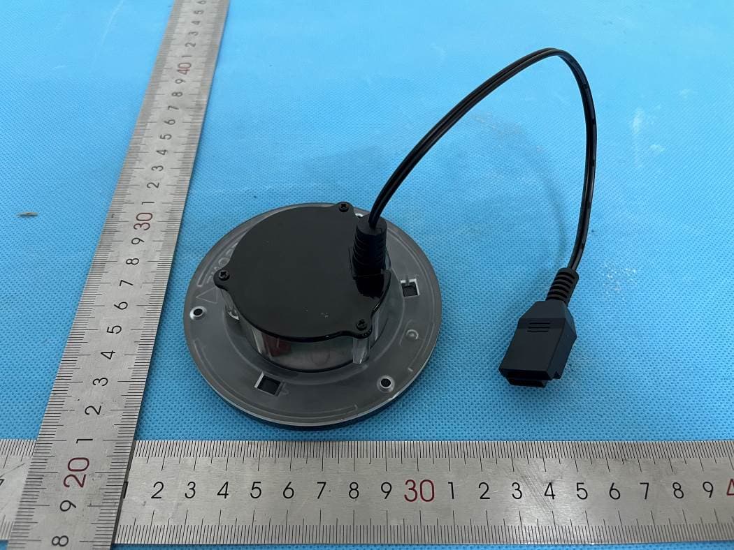
YZHWCPBA01
May 07, 2024Embedded Wireless Charger
Equipment Class
DCD - Part 15 Low Power Transmitter Below 1705 kHz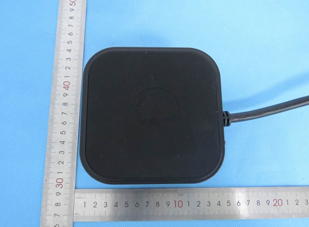
YZHACCPS2QU201
Mar 31, 2024Power Strip
Equipment Class
DCD - Part 15 Low Power Transmitter Below 1705 kHz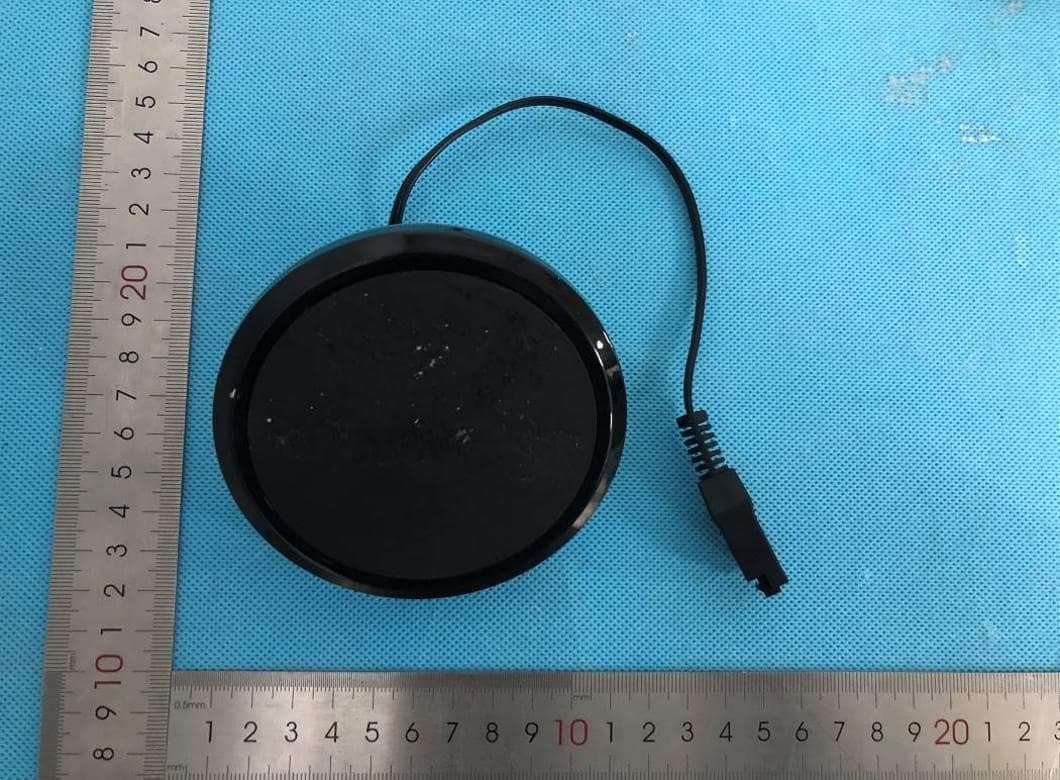
YZHWCPXXX01
Jun 05, 2023Embedded wireless charger
Equipment Class
DCD - Part 15 Low Power Transmitter Below 1705 kHzYZHFTRHCLRF01
Dec 17, 202017 key RGB colorful light belt controller
Equipment Class
DSC - Part 15 Security/Remote Control Transmitter