Z5W-10520141400 MHz band cellular base station
Damm Cellular Systems A/S
Click to zoom
Application Details
- Equipment Class
- TNB - Licensed Non-Broadcast Station Transmitter
- Date of Grant
- Jul 23, 2020
- Application Purpose
- Original Equipment
- Date of Application
- Jul 23, 2020
- Equipment Note
- 400 MHz band cellular base station
- Frequency Range
- 460.00000000 - 470.00000000
- Company
- Damm Cellular Systems A/S
- Country
- Denmark
Documents & Files
Document Text
Text extracted from the exhibit documents filed with the FCC. Open a document above to read the original.
Users Manual
BS422 installation and setup guideline Ver. 1.11 The information contained in this document is the property of Damm Cellular Systems A/S. This document is subject to copyright and shall not be published or reproduced, in whole or in part, without the written permission of Damm Cellular Systems A/S. © 2010 Damm Cellular Systems A/S. All rights reserved. Møllegade 68, DK-6400 Sønderborg, Denmark Phone: +45 74 42 35 00, Fax: +45 74 42 30 31, E-Mail: [email protected], http://www.damm.dk Doc. No. Rev. Date 1.112020-03-06 Damm Cellular Systems A/S, Denmark BS422 Installation and Setup guideline BS422 Installation and setup guideline - Specifications subject to change without notice 2 INTRODUCTION This manual is intended for installation and configuration of the BS422 for operational use. It is recommended that engineers doing the installation and configuration of a BS422 have practical experience in installation of radio and computer systems, and have made themselves familiar with the BS422 equipment through appropriate DAMM training courses and study of the content of the TetraFlex manual and other documentation from DAMM. IMPORTANT: Updates / changes / important information related to the TetraFlex® system and software may be downloaded from the protected part of www.damm.dk Please check this URL for updated information before attempting to install or correct errors NOTE: Chapters marked with a indicate areas where special care must be taken to avoid personal injury or damage to the equipment. Before starting installation and configuration, please read the entire manual carefully. NOTE: It is the responsibility of the system owner / operator to ensure that only authorized service persons has access to the inside circuits of the BS422 NOTE: It is the responsibility of the system owner / operator to ensure that all local legislation, rules and regulations are complied. Internal fuses protect the BS422. Always replace with fuses of equivalent value and type. General Warning This manual contains important safety and operational information. Please read and follow the instructions in this manual. Failure to do so could be hazardous and result in damage to your device. Changes and modifications to this device not expressly proved by DAMM could void the user’s authorization to operate this device Doc. No. Rev. Date 1.112020-03-06 Damm Cellular Systems A/S, Denmark BS422 Installation and Setup guideline BS422 Installation and setup guideline - Specifications subject to change without notice 3 North America regulations The Base Station Transceivers and products devices mentioned in this User Manual comply to FCC part 90 and Industry Canada (IC) RS119 regulations for such equipment. The equipment has been tested and found to comply with the limits for a Class A digital device, pursuant to part 15 of the FCC Rules. These limits are designed to provide reasonable protection against harmful interference when the equipment is operated in a commercial environment. The equipment generates, uses, and can radiate radio frequency energy and, if not installed and used in accordance with the instruction manual, may cause interference to radio communications. Canadian regulations Under Industry Canada regulations, this radio transmitter may only operate using an antenna of a type and maximum (or lesser) gain approved for the transmitter by Industry Canada. To reduce potential radio interference to other users, the antenna type and its gain should be so chosen that the equivalent isotropically radiated power (e.i.r.p.) is not more than that necessary for successful communication. Conformément à la réglementation d'Industrie Canada, le présent émetteur radio peut fonctionner avec une antenne d'un type et d'un gain maximal (ou inférieur) approuvé pour l'émetteur par Industrie Canada. Dans le but de réduire les risques de brouillage radioélectrique à l'intention des autres utilisateurs, il faut choisir le type d'antenne et son gain de sorte que la puissance isotrope rayonnée équivalente (p.i.r.e.) ne dépasse pas l'intensité nécessaire à l'établissement d'une communication satisfaisante. RF Exposure EU: The DAMM developed transmitting devices mentioned in this User Manual have the Nemko approval concerning “Maximum Permissible Exposure Calculations” which are the European limits for maximum permissible exposure defined in the document 1999/519/EC, Council Recommendation of 12. July 1999. A summary of the results is listed below. The specific Nemko Document 128948/5 and 365007-07r01 can be obtained by request from the DAMM Support Department. USA: RF Exposure compliance is determined at time of licensing. Canada: the following minimum safety distances should be maintained based on maximum authorized output power. Au Canada, les distances de sécurité minimales suivantes doivent être respectées en fonction de la puissance de sortie maximale autorisée. RF Exposure Requirements (Canada): Freq. band: 68-174MHz TR type Power Safety Distance m/ft BS422 68MHz 450W E.I.R.P. 273W E.R.P. 5.5/18 BS422 146MHz 794W E.I.R.P. 7.5/24.6 484W E.R.P. 7.5/24.6 Freq. band: 410-470MHz TR type Power Safety Distance m/ft BS422 420-460MHz 794W E.I.R.P. 6.5/21.3 484W E.R.P. 6.5/21.3 Doc. No. Rev. Date 1.112020-03-06 Damm Cellular Systems A/S, Denmark BS422 Installation and Setup guideline BS422 Installation and setup guideline - Specifications subject to change without notice 4 Antennas The outside antenna connected to this device must be installed on an outdoor permanent structure. L'antenne extérieure connectée à cet appareil doit être installée sur une structure permanente extérieure. Notice Do not modify any part of this device for any reason Do not place any combustible material near the transceiver Do not spray any liquid over the device Ensure that the power and antenna connections are securely made, using cables recommended and with excess capacity for the power being utilized. Installing more BS422 according to user manual and using DAMM…
Text truncated - open the document above for the full version.
Cover Letter(s)
Nemko C anada Inc 303 River Road Ottawa, Ontario, Canada K1V 1H2 Attn: Director of Certification Authority to Act as Agent FCC On my behalf, I appoint Allan Slot, Project manager of DAMM Cellular AS to act as my agent in the preparation of this application for equipment certification. I certify that submitted documents properly describe the device or system for which equipment certification is sought. I also certify that each unit manufactured, imported or marketed, as defined in FCC regulations will have affixed to it a label identical to that submitted for approval with this application. In signi ng this letter, Applicant certifies that neither the applicant nor any party to the application is not subject to a denial of Federal benefits, that include FCC benefits, pursuant to Section 5301 of the Anti-Drug Abuse Act of 1988, 21 U.S.C. § 862 because of a conviction for possession or distribution of a controlled substance. See 47 CFR 1.2002(b) for the definition of a "party" for these purposes. For inst ances where our authorized agent signs the application for certification on our behalf, I acknowledge that all responsibility for complying with the terms and conditions for certification, as specified by Nemko Canada Inc, still resides with DAMM Cellular Systems A/S. Dated: 9 /30/2019 Agency agreement expiration date: 9/30/2020 Sincerely,
Cover Letter(s)
DAMM Cellular Systems A/S Møllegade 68 DK-6400 Sønderborg Denmark E-mail: [email protected] Phone: +45 7442 3500 Fax: +45 7442 3230 CVR no. 71257010 www.dammcellular.com To Nemko Canada Inc. 303 River Road Ottawa, Ontario, Canada K1V 1H2 17 February 2020 Spectrum Efficiency Attestation Emission designator Type of information Data rate or # of voice channels 7K60FXW DMR Voice One voice channel per 6.25 kHz bandwidth 7K60FXW DMR Data 9600 bps 6K00F3E; 11K0F3E; 16K0F3E Analogue Voice One voice channel per 6.25 kHz 20K0D1W 0.20TETRA 16 kbps (8 kbps per 6.25 kHz bandwidth) We attest that the transmitter meets a minimum spectrum efficiency standard of one voice channel per 6.25 kHz of channel bandwidth in accordance with 90.203j(4). We further attest that data emission designators meet a minimum spectrum efficiency of 4800 bps per 6.25 kHz of channel bandwidth. Signed,
Cover Letter(s)
DAMM Cellular Systems A/S Møllegade 68 DK-6400 Sønderborg Denmark Phone: +45 7442 3500 Email: [email protected] CVR no. 71257010 www.dammcellular.com To Whom it may concern 3 February 2020 Re: FCC ID: Z5W-10520141 This is to attest that, although the device represented by the above FCC identifier is capable of operating over the entire frequency range 420 - 470 MHz, only the authorized frequencies will be programmed for use in the United States. Regulated parameters are programmed by the manufacturer and cannot be modified by the user. In accordance to 90.203(e), there are no external controls that allow the user to use or program frequencies that are not programmed by the manufacturer, service, or maintenance personnel. Authorized Frequencies Frequency Range MHz) FCC Rule Part(s) 420 - 45090 460 - 462.537590 462.7375 - 467.537590 The entire contiguous frequency range 460 - 470 MHz will be listed on the FCC Grant to reduce the number of entries. 467.7375 - 470 90
External Photos
www.nemko.com External photos.docx; Date: May 2013 ONE WORLDOUR APPROVAL External photos 365560RADWL3 Date of issue: Click here to enter a date. Applicant: DAMM Cellular Systems A/S Product type: cellular base station Model: BS 422 FCC ID: IC Registration number: Z5W-10520141 10159A-10520141 Section 1: External photos Report reference ID: -1RADWL Page 2 of 7 Section 1. External photos 1.1 External photos Figure 9.1-1: Front view photo Section 1: External photos Report reference ID: -1RADWL Page 3 of 7 Figure 9.1-2: Rear view photo Section 1: External photos Report reference ID: -1RADWL Page 4 of 7 Figure 9.1-3: Side view photo Section 1: External photos Report reference ID: -1RADWL Page 5 of 7 Figure 9.1-4: Side view photo Section 1: External photos Report reference ID: -1RADWL Page 6 of 7 Figure 9.1-5: Top view photo Section 1: External photos Report reference ID: -1RADWL Page 7 of 7 Figure 9.1-6: Bottom view photo
ID Label/Location Info
Label location
Test Report
www.nemko.com Nemko Canada Inc., a testing laboratory, is accredited by the Standards Council of Canada. The tests included in this report are within the scope of this accreditation FCC 90 M and RSS-137.docx; Date: May 2014 MRA il ac SCC Accredited LAB LAB Accrédité CCN TM Choose Scandinavian trust Wireless test report – 365560-3TRFWL Applicant: Product type DAMM Cellular Systems A/S 400 MHz band cellular base station Model: FCC ID: IC Registration number: 10520141 Z5W-10520141 10159A-10520141 Specifications: ♦ FCC Part 90, Subpart I Private land mobile radio services ♦ RSS-119 Issue 12, May 2015 Land Mobile and Fixed Equipment Operating in the Frequency Range 27.41-960 MHz Date of issue: July 16, 2020 Yong Huang, Wireless/EMC Specialist Tested by Signature Kevin Rose, Wireless/EMC Specialist Tested by Signature Tom Tidwell, Director Nemko Direct for Telecom Reviewed by Signature Report reference ID: 365560-3TRFWL Page 2 of 75 Test location Company name: Nemko Canada Inc. Address: 292 Labrosse Avenue City: Pointe-Claire Province: Quebec Postal code: H9R 5L8 Country: Canada Telephone: +1 514 694 2684 Facsimile: +1 514 694 3528 Toll free: +1 800 563 6336 Website: www.nemko.com Site number: FCC: CA2041; ISED: 2040G-5 (3 m SAC) Limits of responsibility Note that the results contained in this report relate only to the items tested and were obtained in the period between the date of initial receipt of samples and the date of issue of the report. This test report has been completed in accordance with the requirements of ISO/IEC 17025. All results contain in this report are within Nemko Canada’s ISO/IEC 17025 accreditation. Copyright notification Nemko Canada Inc. authorizes the applicant to reproduce this report provided it is reproduced in its entirety and for use by the company’s employees only. Any use which a third party makes of this report, or any reliance on or decisions to be made based on it, are the responsibility of such third parties. Nemko Canada Inc. accepts no responsibility for damages, if any, suffered by any third party as a result of decisions made or actions based on this report. © Nemko Canada Inc. Report reference ID: 365560-3TRFWL Page 3 of 75 Table of contents Table of contents .......................................................................................................................................................................................................... 3 Section 1. Report summary ................................................................................................................................................................................. 4 1.1 Applicant/Manufacturer........................................................................................................................................................................................... 4 1.2 Test specifications .................................................................................................................................................................................................... 4 1.3 Test methods ............................................................................................................................................................................................................ 4 1.4 Statement of compliance ......................................................................................................................................................................................... 4 1.5 Exclusions ................................................................................................................................................................................................................. 4 1.6 Test report revision history ...................................................................................................................................................................................... 4 Section 2. Summary of test results ....................................................................................................................................................................... 5 2.1 FCC– Intentional Radiators, test results ................................................................................................................................................................... 5 2.2 RSS-119 Issue 12– Intentional Radiators, test results ............................................................................................................................................... 5 Section 3. Equipment under test (EUT) details ..................................................................................................................................................... 6 3.1 EUT information ....................................................................................................................................................................................................... 6 3.2 Technical information .............................................................................................................................................................................................. 6 3.3 Product description and theory of operation ........................................................................................................................................................... 6 Section 4. Engineering considerations .................................................................................................................................................................. 7 4.1 Modifications incorporated in the EUT..................................................................................................................................................................... 7 4.2 Technical judgment ...................................................................................................................................…
Text truncated - open the document above for the full version.
Test Report
Section 8 Testing data Test name Emission limits, conducted method Specification FCC 90.210 and RSS-119 5.8 Report reference ID: 365560-3TRFWL Page 44 of 75 Figure 6.5-33: Conducted Spurious Emissions below 1.2 GHz, Tx @high channel of 460 MHz band, 25W 0.35TETRA modulation Figure 6.5-34: Conducted Spurious Emissions above 1.2 GHz, Tx @high channel of 460 MHz band, 25W 0.35 TETRA modulation Figure 6.5-35: Conducted Spurious Emissions below 1.2 GHz, Tx @high channel of 460 MHz band, 10W 25kHzTEDS modulation Figure 6.5-36: Conducted Spurious Emissions above 1.2 GHz, Tx @high channel of 460 MHz band, 10W 25kHzTEDS modulation Section 8 Testing data Test name Emission limits, conducted method Specification FCC 90.210 and RSS-119 5.8 Report reference ID: 365560-3TRFWL Page 45 of 75 Figure 6.5-37: Conducted Spurious Emissions from inter-modulation products, Tx @low channel of 420 MHz band, 2 X15W 7k60FXW modulation Figure 6.5-38: Conducted Spurious Emissions from inter-modulation products, Tx @low channel of 420 MHz band, 2X15W 16K0F3E modulation Figure 6.5-39: Conducted Spurious Emissions from inter-modulation products, Tx @low channel of 420 MHz band, 2 X10W 0.35TETRA modulation Figure 6.5-40: Conducted Spurious Emissions from inter-modulation products, Tx @low channel of 420 MHz band ,2X7W 25kHzTEDS modulation Section 8 Testing data Test name Emission limits, conducted method Specification FCC 90.210 and RSS-119 5.8 Report reference ID: 365560-3TRFWL Page 46 of 75 Figure 6.5-41: Conducted Spurious Emissions from inter-modulation products, Tx @high channel of 420 MHz band, 2 X15W 7k60FXW modulation Figure 6.5-42: Conducted Spurious Emissions from inter-modulation products, Tx @ high channel of 420 MHz band, 2X15W 16K0F3E modulation Figure 6.5-43: Conducted Spurious Emissions from inter-modulation products, Tx @ high channel of 420 MHz band, 2 X10W 0.35TETRA modulation Figure 6.5-44: Conducted Spurious Emissions from inter-modulation products, Tx @ high channel of 420 MHz band ,2X7W 25kHzTEDS modulation Section 8 Testing data Test name Emission limits, conducted method Specification FCC 90.210 and RSS-119 5.8 Report reference ID: 365560-3TRFWL Page 47 of 75 Figure 6.5-45: Conducted Spurious Emissions from inter-modulation products, Tx @low channel of 460 MHz band, 2 X15W 7k60FXW modulation Figure 6.5-46: Conducted Spurious Emissions from inter-modulation products, Tx @low channel of 460 MHz band, 2X15W 16K0F3E modulation Figure 6.5-47: Conducted Spurious Emissions from inter-modulation products, Tx @low channel of 460 MHz band, 2 X10W 0.35TETRA modulation Figure 6.5-48: Conducted Spurious Emissions from inter-modulation products, Tx @low channel of 460 MHz band ,2X7W 25kHzTEDS modulation Section 8 Testing data Test name Emission limits, conducted method Specification FCC 90.210 and RSS-119 5.8 Report reference ID: 365560-3TRFWL Page 48 of 75 bFigure 6.5-49: Conducted Spurious Emissions from inter-modulation products, Tx @high channel of 460 MHz band, 2 X15W 7k60FXW modulation Figure 6.5-50: Conducted Spurious Emissions from inter-modulation products, Tx @ high channel of 460 MHz band, 2X15W 16K0F3E modulation Figure 6.5-51: Conducted Spurious Emissions from inter-modulation products, Tx @ high channel of 460 MHz band, 2 X10W 0.35TETRA modulation Figure 6.5-52: Conducted Spurious Emissions from inter-modulation products, Tx @ high channel of 460 MHz band ,2X7W 25kHzTEDS modulation Section 8 Testing data Test name Emission limits, radiated method Specification FCC 90.210 and RSS-119 5.8 Report reference ID: 365560-3TRFWL Page 49 of 75 6.6 FCC 90.210 and RSS-119 5.8 Emission limits, radiated method 6.6.1 Definitions and limits FCC §90.210 (b) Emission Mask B. For transmitters that are equipped with an audio low-pass filter, the power of any emission must be attenuated below the unmodulated carrier power (P) as follows: (1) On any frequency removed from the assigned frequency by more than 50 percent, but not more than 100 percent of the authorized bandwidth: At least 25 dB. (2) On any frequency removed from the assigned frequency by more than 100 percent, but not more than 250 percent of the authorized bandwidth: At least 35 dB. (3) On any frequency removed from the assigned frequency by more than 250 percent of the authorized bandwidth: At least 43 + 10 log (P) dB. (d) Emission Mask D—12.5 kHz channel bandwidth equipment. For transmitters designed to operate with a 12.5 kHz channel bandwidth, any emission must be attenuated below the power (P) of the highest emission contained within the authorized bandwidth as follows: (1) On any frequency from the center of the authorized bandwidth f 0 to 5.625 kHz removed from f 0 : Zero dB. (2) On any frequency removed from the center of the authorized bandwidth by a displacement frequency (f d in kHz) of more than 5.625 kHz but no more than 12.5 kHz: At least 7.27(f d −2.88 kHz) dB. (3) On any frequency removed from the center of the authorized bandwidth by a displacement frequency (f d in kHz) of more than 12.5 kHz: At least 50 + 10 log (P) dB or 70 dB, whichever is the lesser attenuation. (4) The reference level for showing compliance with the emission mask shall be established using a resolution bandwidth sufficiently wide (usually two or three times the channel bandwidth) to capture the true peak emission of the equipment under test. In order to show compliance with the emission mask up to and including 50 kHz removed from the edge of the authorized bandwidth, adjust the resolution bandwidth to 100 Hz with the measuring instrument in a peak hold mode. A sufficient number of sweeps must be measured to insure that the emission profile is developed. If video filtering is used, its bandwidth must not be less than the instrument resolution bandwidth. For emissions beyond 50 kHz from the edge of the authorized bandwidth, see paragraph (o) of this section. If it can be shown that use of the above instrumentation settings does not accurately represent the true i…
Text truncated - open the document above for the full version.
Test Setup Photos
www.nemko.com setup photos.docx; Date: May 2013 ONE WORLDOUR APPROVAL Setup photos 365560RADWL Date of issue: Click here to enter a date. Applicant: DAMM Cellular Systems A/S Product: cellular base station Model: 10520141 FCC ID: IC Registration number: Z5W-10520141 10159A-10520141 Section 1: setup photos Report reference ID: - Page 2 of 4 Section 1. Setup photos 1.1 Radiated Front view Section 1: setup photos Report reference ID: - Page 3 of 4 1.2 Radiated back view Section 1: setup photos Report reference ID: - Page 4 of 4 1.3 Conducted view
Contact Information
Applicant
Tommy Trip(Group CEO)
Test Firm
Nemko Canada Inc. (Montreal)Charles Neal
Technical Specifications
| # | Rule Parts | Frequency Range | Power Output | Emission | Tolerance |
|---|---|---|---|---|---|
| 11 | 9 | 460 MHz - 470 MHz | 50 W | 21K0D1W | 0.33 ppm |
Other Applications from Damm Cellular Systems A/S

Z5W-10520111
May 19, 2020150 MHz band cellular base station
Equipment Class
TNB - Licensed Non-Broadcast Station Transmitter
Z5W-10520101
May 13, 202070 MHz band cellular base station
Equipment Class
TNB - Licensed Non-Broadcast Station Transmitter
Z5W-105003
Mar 06, 2013Base Station
Equipment Class
TNB - Licensed Non-Broadcast Station Transmitter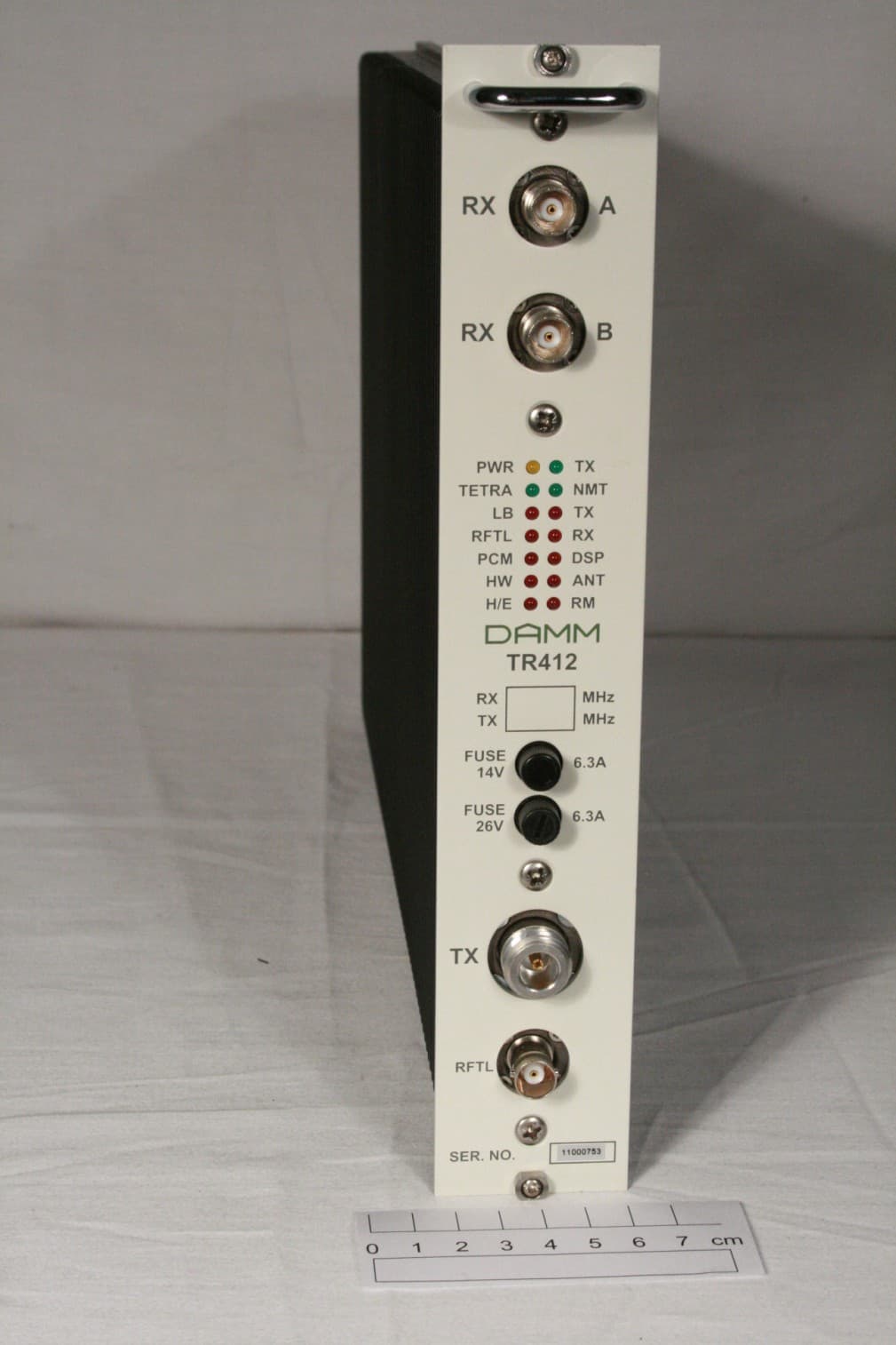
Z5W-104013
Mar 06, 2013Door System Transmitter
Equipment Class
TNB - Licensed Non-Broadcast Station Transmitter
Z5W-105002
Nov 01, 2012Base station transceiver
Equipment Class
TNB - Licensed Non-Broadcast Station Transmitter